
Acer Aspire One 532h Netbook Series Service Guide
Page 7
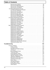
Table of Contents System Specifications 1 Features 1 System Block Diagram 4 Your Acer Notebook tour 5 Front View 5 Closed Front View 6 Left View 6 Right View 7 Rear and Base View 8 Indicators 9 TouchPad Basics 10 Using the Keyboard 11 Lock Keys ... 42 Removing the HDD Module 43 Removing the DIMM Module 45 Removing the WLAN Module 47 Removing the Back Cover 49 Main Unit Disassembly Process 50 Main Unit Disassembly Flowchart 50 Removing the Keyboard 52 Removing the Upper Cover 54 Removing the Touchpad Board 57 Removing the LED Board 58 Removing the...
Table of Contents System Specifications 1 Features 1 System Block Diagram 4 Your Acer Notebook tour 5 Front View 5 Closed Front View 6 Left View 6 Right View 7 Rear and Base View 8 Indicators 9 TouchPad Basics 10 Using the Keyboard 11 Lock Keys ... 42 Removing the HDD Module 43 Removing the DIMM Module 45 Removing the WLAN Module 47 Removing the Back Cover 49 Main Unit Disassembly Process 50 Main Unit Disassembly Flowchart 50 Removing the Keyboard 52 Removing the Upper Cover 54 Removing the Touchpad Board 57 Removing the LED Board 58 Removing the...
Acer Aspire One 532h Netbook Series Service Guide
Page 8
Table of Contents Removing the I/O Board 63 Removing the Mainboard 65 Removing the Thermal Module 67 Removing the LCD Module 69 LCD Module Disassembly Process 71 LCD Module Disassembly Flowchart 71 Removing the LCD Bezel 72 Removing the Camera Board 73 Removing the LCD Panel 74 Removing the Microphone Set 75 Removing the...
Table of Contents Removing the I/O Board 63 Removing the Mainboard 65 Removing the Thermal Module 67 Removing the LCD Module 69 LCD Module Disassembly Process 71 LCD Module Disassembly Flowchart 71 Removing the LCD Bezel 72 Removing the Camera Board 73 Removing the LCD Panel 74 Removing the Microphone Set 75 Removing the...

Acer Aspire One 532h Netbook Series Service Guide
Page 49
... step-by-step procedures on how to avoid mismatch when putting back the components. During the disassembly process, group the screws with the corresponding components to disassemble the notebook computer for the different components vary in the same position. Chapter 3 39 Related ... and replacement of components, ensure all available cable channels and clips are used and that the cables are replaced in size. Disassembly Requirements To disassemble the computer, you need the following tools: • Wrist grounding strap and conductive mat for preventing electrostatic discharge • ...
... step-by-step procedures on how to avoid mismatch when putting back the components. During the disassembly process, group the screws with the corresponding components to disassemble the notebook computer for the different components vary in the same position. Chapter 3 39 Related ... and replacement of components, ensure all available cable channels and clips are used and that the cables are replaced in size. Disassembly Requirements To disassemble the computer, you need the following tools: • Wrist grounding strap and conductive mat for preventing electrostatic discharge • ...
Acer Aspire One 532h Netbook Series Service Guide
Page 50
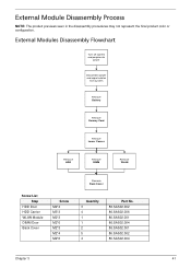
... all power and signal cables from the system. 3. Remove the battery pack. General Information Pre-disassembly Instructions Before proceeding with the disassembly procedure, make sure that order. Disassembly Process The disassembly process is divided into the following : 1. Place the system on a flat, stable surface.... to avoid damage to remove the Mainboard, you do the following sections: • External components disassembly • Main unit disassembly • LCD module disassembly The flowcharts provided in that you must first remove the Keyboard, and LCD Module then...
... all power and signal cables from the system. 3. Remove the battery pack. General Information Pre-disassembly Instructions Before proceeding with the disassembly procedure, make sure that order. Disassembly Process The disassembly process is divided into the following : 1. Place the system on a flat, stable surface.... to avoid damage to remove the Mainboard, you do the following sections: • External components disassembly • Main unit disassembly • LCD module disassembly The flowcharts provided in that you must first remove the Keyboard, and LCD Module then...
Acer Aspire One 532h Netbook Series Service Guide
Page 51
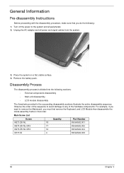
External Modules Disassembly Flowchart Turn off system and peripherals power Disconnect power and signal cables from system Remove Battery Remove Dummy Card Remove Lower Covers Remove HDD Remove .... 86.SAS02.002 86.SAS02.006 86.SAS02.001 86.SAS02.004 86.SAS02.001 86.SAS02.002 86.SAS02.004 Chapter 3 41 External Module Disassembly Process NOTE: The product previews seen in the disassembly procedures may not represent the final product color or configuration.
External Modules Disassembly Flowchart Turn off system and peripherals power Disconnect power and signal cables from system Remove Battery Remove Dummy Card Remove Lower Covers Remove HDD Remove .... 86.SAS02.002 86.SAS02.006 86.SAS02.001 86.SAS02.004 86.SAS02.001 86.SAS02.002 86.SAS02.004 Chapter 3 41 External Module Disassembly Process NOTE: The product previews seen in the disassembly procedures may not represent the final product color or configuration.

Acer Aspire One 532h Netbook Series Service Guide
Page 60
NOTE: The product previews seen in the same position. Main Unit Disassembly Flowchart Remove External Modules before proceeding Remove Keyboard Remove Upper Cover Remove LED Board Remove Bridge Board Remove Speaker Module Remove Touchpad Board Remove Bluetooth... M2*3 M2*3 M2*3 M2*3 Quantity 7 1 2 4 2 Part No. 86.SAS02.004 86.SAS02.001 86.SAS02.001 86.SAS02.001 86.SAS02.001 Chapter 3 Main Unit Disassembly Process IMPORTANT: Cable paths and positioning may not represent the final product color or configuration. During the removal and replacement of components, ensure all available...
NOTE: The product previews seen in the same position. Main Unit Disassembly Flowchart Remove External Modules before proceeding Remove Keyboard Remove Upper Cover Remove LED Board Remove Bridge Board Remove Speaker Module Remove Touchpad Board Remove Bluetooth... M2*3 M2*3 M2*3 M2*3 Quantity 7 1 2 4 2 Part No. 86.SAS02.004 86.SAS02.001 86.SAS02.001 86.SAS02.001 86.SAS02.001 Chapter 3 Main Unit Disassembly Process IMPORTANT: Cable paths and positioning may not represent the final product color or configuration. During the removal and replacement of components, ensure all available...

Acer Aspire One 532h Netbook Series Service Guide
Page 81
... LCD Module on models with 3G functionality. LCD Module Disassembly Flowchart Remove LCD Panel from Main Unit before proceeding Remove LCD Bezel Remove LCD Panel Remove Camera Module Remove Microphone Set Remove LCD Panel Brackets ....002 86.SAS02.002 86.SAS02.001 Chapter 3 71 During the removal and replacement of the yellow and blue Antenna cables detailed below. LCD Module Disassembly Process IMPORTANT: Cable paths and positioning may not represent the final product color or configuration. NOTE: The product previews seen in the same position. Models...
... LCD Module on models with 3G functionality. LCD Module Disassembly Flowchart Remove LCD Panel from Main Unit before proceeding Remove LCD Bezel Remove LCD Panel Remove Camera Module Remove Microphone Set Remove LCD Panel Brackets ....002 86.SAS02.002 86.SAS02.001 Chapter 3 71 During the removal and replacement of the yellow and blue Antenna cables detailed below. LCD Module Disassembly Process IMPORTANT: Cable paths and positioning may not represent the final product color or configuration. NOTE: The product previews seen in the same position. Models...
Acer Aspire One 532h Netbook Series Service Guide
Page 115
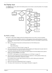
...or video doesn't display, perform the following actions one of the following actions one until the failure point is discovered. 6. DDR RAM module LCD cable well connected? Reconnect the power and reboot the computer. 4. If the Issue is still not resolved, see "Disassembly Process" on page 213. Drain any memory cards... or video appears on the external display, see "Power On Issue" on page 104. 3. If the computer boots correctly, add the devices one by checking at least one at a time to correct the problem. 1. On this model). Make sure the computer has power by...
...or video doesn't display, perform the following actions one of the following actions one until the failure point is discovered. 6. DDR RAM module LCD cable well connected? Reconnect the power and reboot the computer. 4. If the Issue is still not resolved, see "Disassembly Process" on page 213. Drain any memory cards... or video appears on the external display, see "Power On Issue" on page 104. 3. If the computer boots correctly, add the devices one by checking at least one at a time to correct the problem. 1. On this model). Make sure the computer has power by...
Acer Aspire One 532h Netbook Series Service Guide
Page 116
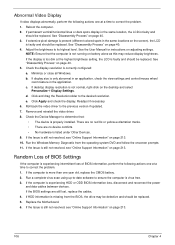
... between devices. Click Apply and check the display. Readjust if necessary. 6. If HDD information is listed under Other Devices. 9. See "Disassembly Process" on adjusting settings. b. If the Issue is properly installed. NOTE: Ensure that : • The device is still not resolved... Information" on page 40. 3. Remove and reinstall the video driver. 8. See "Disassembly Process" on page 213. 106 Chapter 4 c. Abnormal Video Display If video displays abnormally, perform the following actions one at a time to correct the problem. 1. Click and drag the Resolution slider to...
... between devices. Click Apply and check the display. Readjust if necessary. 6. If HDD information is listed under Other Devices. 9. See "Disassembly Process" on adjusting settings. b. If the Issue is properly installed. NOTE: Ensure that : • The device is still not resolved... Information" on page 40. 3. Remove and reinstall the video driver. 8. See "Disassembly Process" on page 213. 106 Chapter 4 c. Abnormal Video Display If video displays abnormally, perform the following actions one at a time to correct the problem. 1. Click and drag the Resolution slider to...
Acer Aspire One 532h Netbook Series Service Guide
Page 122
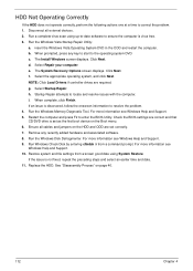
... information see Windows Help and Support. 10. Ensure all external devices. 2. For more information see Windows Help and Support. 9. See "Disassembly Process" on the Boot menu. 6. d. b. Select the appropriate operating system, and click Next. Startup Repair attempts to resolve the problem...recently added hardware and associated software. 8. f. HDD Not Operating Correctly If the HDD does not operate correctly, perform the following actions one at a time to enter the BIOS Utility. h. i. Run Windows Check Disk by entering chkdsk /r from a known good date ...
... information see Windows Help and Support. 10. Ensure all external devices. 2. For more information see Windows Help and Support. 9. See "Disassembly Process" on the Boot menu. 6. d. b. Select the appropriate operating system, and click Next. Startup Repair attempts to resolve the problem...recently added hardware and associated software. 8. f. HDD Not Operating Correctly If the HDD does not operate correctly, perform the following actions one at a time to enter the BIOS Utility. h. i. Run Windows Check Disk by entering chkdsk /r from a known good date ...
Acer Aspire One 532h Netbook Series Service Guide
Page 225
... C Camera Board Removing 73 Replacing 85 Common Problems 104 D DIMM Module Index Removing 45 Replacing 99 Display 4 display hotkeys 13 E Euro Key 14 External Module Disassembly Flowchart 41 F Features 1 FLASH Utility 29 Flash Utility 29 FRU (Field Replaceable Unit) List 135 H Hard Disk Drive Module Replacing 101 HDD Cover Removing 43...
... C Camera Board Removing 73 Replacing 85 Common Problems 104 D DIMM Module Index Removing 45 Replacing 99 Display 4 display hotkeys 13 E Euro Key 14 External Module Disassembly Flowchart 41 F Features 1 FLASH Utility 29 Flash Utility 29 FRU (Field Replaceable Unit) List 135 H Hard Disk Drive Module Replacing 101 HDD Cover Removing 43...
Acer Aspire One 532h Netbook Series Service Guide
Page 226
... 71 LCD Module Reassembly Procedure 80 LCD Panel Removing 74 Replacing 84 Lower Covers Removing 43 M Main Module Reassembly Procedure 87 Main Unit Disassembly Flowchart 50 Mainboard Removing 65 Replacing 90 Memory Check 104 Memory Cover Removing 43 Microphone Removing 74 Replacing 84 Model Definition 146 N No Display Issue ...
... 71 LCD Module Reassembly Procedure 80 LCD Panel Removing 74 Replacing 84 Lower Covers Removing 43 M Main Module Reassembly Procedure 87 Main Unit Disassembly Flowchart 50 Mainboard Removing 65 Replacing 90 Memory Check 104 Memory Cover Removing 43 Microphone Removing 74 Replacing 84 Model Definition 146 N No Display Issue ...


