
AL1715 Service Guide
Page 5
If you are not blocked or covered. Do not overload power strips and extension cords. opening or removing covers can expose you mount the monitor on a bed, sofa, rug or similar surface. To ensure satisfactory operation, use an adapter to service the monitor yourself; If you to your home, consult your outlet does not accommodate the three-wire plug, have appropriate configured receptacles marked...
If you are not blocked or covered. Do not overload power strips and extension cords. opening or removing covers can expose you mount the monitor on a bed, sofa, rug or similar surface. To ensure satisfactory operation, use an adapter to service the monitor yourself; If you to your home, consult your outlet does not accommodate the three-wire plug, have appropriate configured receptacles marked...

AL1715 Service Guide
Page 8
...-200 Signal Interface Sync Type for the 17" MICRO-PROCESSOR based Multi-mode supported high resolution color LCD monitor. There is a build-in addition MTBF target is also a space saving design, allowing more . Monitor Feature INTRODUCTION Chapter 1 Scope This specification defines the requirements for analog input DSUB Separate / compatible / AR578 Normal 17" panel HYDIS HT17E12-200 DSUB Separate / compatible / Color Temp user adjust Support Support DDC Speaker Headphone Jack Microphone Jack USB Hub Tilt / Swivel Height Adjust...
...-200 Signal Interface Sync Type for the 17" MICRO-PROCESSOR based Multi-mode supported high resolution color LCD monitor. There is a build-in addition MTBF target is also a space saving design, allowing more . Monitor Feature INTRODUCTION Chapter 1 Scope This specification defines the requirements for analog input DSUB Separate / compatible / AR578 Normal 17" panel HYDIS HT17E12-200 DSUB Separate / compatible / Color Temp user adjust Support Support DDC Speaker Headphone Jack Microphone Jack USB Hub Tilt / Swivel Height Adjust...

AL1715 Service Guide
Page 9
... lux = foot-candle x 10.76 - 9 - Minolta CA100 photometer, or equivalent Control settings User brightness control : Maximum (unless otherwise specified ) User contrast control: Typical (unless otherwise specified ) User red/white balance, Green/white balance and Blue/white balance control : In the center (unless otherwise specified ) Power input: 110Vac or 230Vac Ambient temperature: 20 ± 5 ˚C ( 68 ± 9 ˚ F) Analog input mode: 1280 x1024 /60 Hz MEASUREMENT SYSTEMS The units of measure stated...
... lux = foot-candle x 10.76 - 9 - Minolta CA100 photometer, or equivalent Control settings User brightness control : Maximum (unless otherwise specified ) User contrast control: Typical (unless otherwise specified ) User red/white balance, Green/white balance and Blue/white balance control : In the center (unless otherwise specified ) Power input: 110Vac or 230Vac Ambient temperature: 20 ± 5 ˚C ( 68 ± 9 ˚ F) Analog input mode: 1280 x1024 /60 Hz MEASUREMENT SYSTEMS The units of measure stated...

AL1715 Service Guide
Page 10
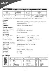
..., (standard VGA video) 3.5 mm stereo audio jack (Audio) (For AR577 only) Audio power: 0.5Wrms + 0.5Wrms (300Hz - 10kHz (S.P.L. - 10 dB))(AR577 only) Front control: power on/off with LED select adjustment (+,-) Interface frequency Horizontal Frequency 24KHz --80KHz Vertical Frequency 49Hz ------75Hz Plug & play: Support VESA DDC2B functions Power Input voltage: Single phase, 50/60HZ, 100 VAC to 240VAC ±10% Total output power: 60 Watt max. - 10 - LCD monitor General specification Panel Type: 17 " active matrix color TFT LCD 1).
..., (standard VGA video) 3.5 mm stereo audio jack (Audio) (For AR577 only) Audio power: 0.5Wrms + 0.5Wrms (300Hz - 10kHz (S.P.L. - 10 dB))(AR577 only) Front control: power on/off with LED select adjustment (+,-) Interface frequency Horizontal Frequency 24KHz --80KHz Vertical Frequency 49Hz ------75Hz Plug & play: Support VESA DDC2B functions Power Input voltage: Single phase, 50/60HZ, 100 VAC to 240VAC ±10% Total output power: 60 Watt max. - 10 - LCD monitor General specification Panel Type: 17 " active matrix color TFT LCD 1).
AL1715 Service Guide
Page 12
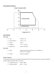
...match the supported timing the display optimization will not be assured. • Horizontal Frequency • Vertical Frequency 24KHz --80KHz 49Hz -------75Hz - 12 - Panel Relative Humidity Input Signals Video input • Type • Input Impedance • Polarity • Amplitude • Display Color Sync input • Signal • Polarity Analog R, G, B. 75 ohm +/- 2% Positive 0 - 0.7 +/- 0.05 Vp same as LCD panel separate horizontal and vertical sync, or composite sync which are TTL compatible positive and negative. Interface frequency The following frequency range is...
...match the supported timing the display optimization will not be assured. • Horizontal Frequency • Vertical Frequency 24KHz --80KHz 49Hz -------75Hz - 12 - Panel Relative Humidity Input Signals Video input • Type • Input Impedance • Polarity • Amplitude • Display Color Sync input • Signal • Polarity Analog R, G, B. 75 ohm +/- 2% Positive 0 - 0.7 +/- 0.05 Vp same as LCD panel separate horizontal and vertical sync, or composite sync which are TTL compatible positive and negative. Interface frequency The following frequency range is...

AL1715 Service Guide
Page 19
... mode. 18. In standby mode? 11. Update the lift time of brightness from analog port? 16. Process the OSD display. 19. Program the eeprom by default values. 4. Is the power key pressed? 6. Check the analog port, are there any signal coming from eeprom. 5. Display "Cable Not Connected" message, and go into eeprom. Get the PWM value of back light. 12. Software Flow Chart 1. MCU initialize 2. Enter factory mode 9. Read the key board...
... mode. 18. In standby mode? 11. Update the lift time of brightness from analog port? 16. Process the OSD display. 19. Program the eeprom by default values. 4. Is the power key pressed? 6. Check the analog port, are there any signal coming from eeprom. 5. Display "Cable Not Connected" message, and go into eeprom. Get the PWM value of back light. 12. Software Flow Chart 1. MCU initialize 2. Enter factory mode 9. Read the key board...
AL1715 Service Guide
Page 20
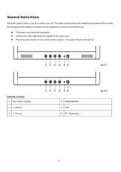
Connect the video cable from the monitor to turn the monitor on the monitor position. The power indicator will light up. The power cord should be adjusted to your personal preferences. General Instructions Press the power button to turn on or off. By changing these settings, the picture can be connected. AR577 External Controls 1 Auto Adjust Key/Exit 2 / Volume 4 MENU/ENTER 5 LED 6 / Power Key AR578 - 20 - Press the power button to the video card. The other control buttons are located at front panel of the monitor.
Connect the video cable from the monitor to turn the monitor on the monitor position. The power indicator will light up. The power cord should be adjusted to your personal preferences. General Instructions Press the power button to turn on or off. By changing these settings, the picture can be connected. AR577 External Controls 1 Auto Adjust Key/Exit 2 / Volume 4 MENU/ENTER 5 LED 6 / Power Key AR578 - 20 - Press the power button to the video card. The other control buttons are located at front panel of the monitor.
AL1715 Service Guide
Page 24
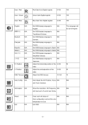
... N/A Reset N/A Exit N/A Red Gain from Digital-register. 0-100 Green Gain Digital-register. 0-100 Blue Gain from Digital-register. 0-100 Set OSD display language to N/A Japanese. Set OSD display language to N/A English. Adjust the OSD timeout. 10-120 Auto Adjust the H/V Position, Focus N/A and Clock of the 0-100 OSD. Set OSD display language to Italian. N/A Set OSD display language to N/A German. Adjust the verticalposition of picture. Show the resolution, H/V frequency N/A and input port of the 0-100 OSD. Adjust the horizontal position of...
... N/A Reset N/A Exit N/A Red Gain from Digital-register. 0-100 Green Gain Digital-register. 0-100 Blue Gain from Digital-register. 0-100 Set OSD display language to N/A Japanese. Set OSD display language to N/A English. Adjust the OSD timeout. 10-120 Auto Adjust the H/V Position, Focus N/A and Clock of the 0-100 OSD. Set OSD display language to Italian. N/A Set OSD display language to N/A German. Adjust the verticalposition of picture. Show the resolution, H/V frequency N/A and input port of the 0-100 OSD. Adjust the horizontal position of...
AL1715 Service Guide
Page 25
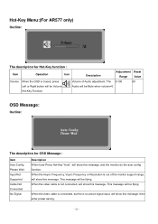
... Auto Config Please Wait Input Not Supported Cable Not Connected No Signal Description When User Press Hot-Key "Auto", will be flying. When the Hsync Frequency, Vsync Frequency or Resolution is closed, press Volume of the monitor support range, will show this message. This message will show this message. Hot-Key Function OSD Message: Outline: The description for Hot-Key function : Item Operation Icon Description Adjustment Reset Range Value Volume...
... Auto Config Please Wait Input Not Supported Cable Not Connected No Signal Description When User Press Hot-Key "Auto", will be flying. When the Hsync Frequency, Vsync Frequency or Resolution is closed, press Volume of the monitor support range, will show this message. This message will show this message. Hot-Key Function OSD Message: Outline: The description for Hot-Key function : Item Operation Icon Description Adjustment Reset Range Value Volume...

AL1715 Service Guide
Page 27
... DDC2B feature This monitor is no video-input signal present. Please note that power supply card needs to inform the host system of its display capabilities. This reduces the monitor's internal power supply consumption. It allows the monitor to use a cord set by reducing power consumption when there is the wallet plug with a grounding type attachment plug, rated 10A, 250V,CEE-22 male configuration. The voltage rating for connection to a "Screen Saver" feature...
... DDC2B feature This monitor is no video-input signal present. Please note that power supply card needs to inform the host system of its display capabilities. This reduces the monitor's internal power supply consumption. It allows the monitor to use a cord set by reducing power consumption when there is the wallet plug with a grounding type attachment plug, rated 10A, 250V,CEE-22 male configuration. The voltage rating for connection to a "Screen Saver" feature...
AL1715 Service Guide
Page 64
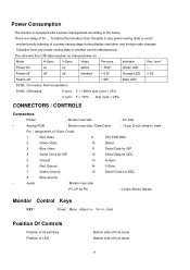
.... V-Sync. Power-off off off blanked < 5 W Orange LED < 5S Switch-off < 5W Dark LED SYNC. Mode H-Sync. Indicator Rec. F < 10KHz duty cycle > 25% V sync. Power : Monitor rear side : AC Inlet - Audio : Monitor rear side : -PC I/P for PC : 3.5mm Stereo female Monitor Control Keys KEY : Power , Menu , Adjust +/- , Vol +/-, Auto Position Of Controls Position of all switches Position of LED : Bottom side of front bezel : Bottom side of 15-pin D-sub: 1 Red Video 9 +5V FOR DDC 2 Green Video 10 Detect 3 Blue Video...
.... V-Sync. Power-off off off blanked < 5 W Orange LED < 5S Switch-off < 5W Dark LED SYNC. Mode H-Sync. Indicator Rec. F < 10KHz duty cycle > 25% V sync. Power : Monitor rear side : AC Inlet - Audio : Monitor rear side : -PC I/P for PC : 3.5mm Stereo female Monitor Control Keys KEY : Power , Menu , Adjust +/- , Vol +/-, Auto Position Of Controls Position of all switches Position of LED : Bottom side of front bezel : Bottom side of 15-pin D-sub: 1 Red Video 9 +5V FOR DDC 2 Green Video 10 Detect 3 Blue Video...

AL1715 User Guide
Page 1
... Safety Instructions...3 Chapter 1 Installation ...4 Unpacking...4 Connecting the LCD Monitor and Base 4 Viewing Angle Adjustment ...4 Detaching LCD Monitor from Its Stand 5 Interface for Arm Applications ...5 Connecting the Display...5 Connecting the AC Power ...5 Connecting the Audio Cable (For AL1715 m and AL1715 bm 6 Power Management System...6 Chapter 2 Display Controls 7 General Instructions...7 Front Panel Control ...8 How To Adjust A Setting ...9 Adjusting The Picture ...9 Chapter 3 Technical Information 11 Specifications...11 Standard Timing Table ...13 Troubleshooting...15...
... Safety Instructions...3 Chapter 1 Installation ...4 Unpacking...4 Connecting the LCD Monitor and Base 4 Viewing Angle Adjustment ...4 Detaching LCD Monitor from Its Stand 5 Interface for Arm Applications ...5 Connecting the Display...5 Connecting the AC Power ...5 Connecting the Audio Cable (For AL1715 m and AL1715 bm 6 Power Management System...6 Chapter 2 Display Controls 7 General Instructions...7 Front Panel Control ...8 How To Adjust A Setting ...9 Adjusting The Picture ...9 Chapter 3 Technical Information 11 Specifications...11 Standard Timing Table ...13 Troubleshooting...15...

AL1715 User Guide
Page 4
... AL1715 bm) * 1.8M Power Cord * Base If you open the box to -PC VGA Cable * 1.8M Stereo Jack Audio Cable (for sufficient airflow. Then connect the LCD Monitor and base please.(See fig.1-1 ) Viewing Angle Adjustment The LCD Monitor is designed to allow users to +15°.(See fig. 1-2) Figure 1-1 Figure 1-2 Warning Do not force the LCD Monitor over its maximum viewing angle settings as stated above. You need a stable and clean surface near a wall power...
... AL1715 bm) * 1.8M Power Cord * Base If you open the box to -PC VGA Cable * 1.8M Stereo Jack Audio Cable (for sufficient airflow. Then connect the LCD Monitor and base please.(See fig.1-1 ) Viewing Angle Adjustment The LCD Monitor is designed to allow users to +15°.(See fig. 1-2) Figure 1-1 Figure 1-2 Warning Do not force the LCD Monitor over its maximum viewing angle settings as stated above. You need a stable and clean surface near a wall power...

AL1715 User Guide
Page 5
... holes in the plastic covering as illustrated in Figure 1-4. Connecting the AC Power 1. The rear of the signal cable to release. Connect the power cord to an AC power source. 5 Figure 1-3 Figure 1-4 Figure 1-5 Figure 1-6 Connecting the Display 1. Detaching LCD Monitor from Its Stand Unscrew screws the swivel base support column and pull down the hinge to the VGA port on your computer. 2. These specifications meet the VESA Flat Panel Monitor Physical Mounting Interface Standard (paragraphs 2.1 and...
... holes in the plastic covering as illustrated in Figure 1-4. Connecting the AC Power 1. The rear of the signal cable to release. Connect the power cord to an AC power source. 5 Figure 1-3 Figure 1-4 Figure 1-5 Figure 1-6 Connecting the Display 1. Detaching LCD Monitor from Its Stand Unscrew screws the swivel base support column and pull down the hinge to the VGA port on your computer. 2. These specifications meet the VESA Flat Panel Monitor Physical Mounting Interface Standard (paragraphs 2.1 and...
AL1715 User Guide
Page 8
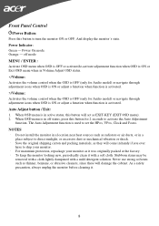
... removed with a cloth lightly dampened with a soft cloth. Front Panel Control /Power Button: Press this button to set the HPos, VPos, Clock and Focus. When OSD menu is used to turn the monitor ON or OFF, And display the monitor's state. For maximum protection, repackage your monitor. Power On mode. To keep the monitor looking new, periodically clean it . 8 As a safety precaution, always unplug the monitor before cleaning it with a mild detergent solution. Auto Adjust button...
... removed with a cloth lightly dampened with a soft cloth. Front Panel Control /Power Button: Press this button to set the HPos, VPos, Clock and Focus. When OSD menu is used to turn the monitor ON or OFF, And display the monitor's state. For maximum protection, repackage your monitor. Power On mode. To keep the monitor looking new, periodically clean it . 8 As a safety precaution, always unplug the monitor before cleaning it with a mild detergent solution. Auto Adjust button...
AL1715 User Guide
Page 9
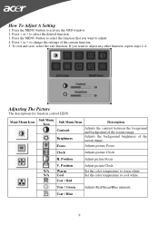
... control LEDS Main Menu Icon Sub Menu Icon Sub Menu Item Contrast Brightness Description Adjusts the contrast between the foreground and background of the screen image. Focus Adjusts picture Focus Clock Adjusts picture Clock H. Press < or > to warm white. Adjusts the background brightness of the screen image. Position N/A Warm N/A Cool User / Red Adjust picture Clock Set the color temperature to change the settings of the current function. 5. User / Green Adjusts Red/Green/Blue intensity. How To Adjust A Setting 1. User / Blue 9 If you want to adjust...
... control LEDS Main Menu Icon Sub Menu Icon Sub Menu Item Contrast Brightness Description Adjusts the contrast between the foreground and background of the screen image. Focus Adjusts picture Focus Clock Adjusts picture Clock H. Press < or > to warm white. Adjusts the background brightness of the screen image. Position N/A Warm N/A Cool User / Red Adjust picture Clock Set the color temperature to change the settings of the current function. 5. User / Green Adjusts Red/Green/Blue intensity. How To Adjust A Setting 1. User / Blue 9 If you want to adjust...

AL1715 User Guide
Page 10
V. N/A Information Show the resolution, H/V frequency and input port of Auto-configuration and set the color temperature to Cool. N/A Reset Clear each old status of current iput timing. N/A Exit Save user adjustment and OSD disappear. 10 Position Adjust the vertical position of the OSD. Adjust the horizontal position of the OSD. N/A Auto Config Auto Adjust the H/V Position, Focus and Clock of picture. Position Multi-language selection. OSD Timeout Adjust the OSD timeout. N/A English N/A N/A Deutsch N/A Français N/A Español N/A Italiano N/A 简 N/A...
V. N/A Information Show the resolution, H/V frequency and input port of Auto-configuration and set the color temperature to Cool. N/A Reset Clear each old status of current iput timing. N/A Exit Save user adjustment and OSD disappear. 10 Position Adjust the vertical position of the OSD. Adjust the horizontal position of the OSD. N/A Auto Config Auto Adjust the H/V Position, Focus and Clock of picture. Position Multi-language selection. OSD Timeout Adjust the OSD timeout. N/A English N/A N/A Deutsch N/A Français N/A Español N/A Italiano N/A 简 N/A...

AL1715 User Guide
Page 11
...; ~ +65° Horizontal: -80° ~ +80° 16.7M with FRC or Dithering Video Input Signal Input Impedance Polarity Amplitude Multi-mode Supported Analogue RGB 0.7Vp-p 75 Ohm ± 2% Positive, Negative 0 - 0.7 ± 0.05 Vp Horizontal Frequency: 24 ~ 80 KHz Vertical Frequency: 49 ~ 75 Hz Control Power switch On/Off switch with LED indicator Audio (AL1715 m/AL1715 bm) Input 500mVrms Output 1W+1W OSD Brightness Contrast Horizontal Position Vertical Position Phase Clock Display Mode Setup Digital Digital Digital Digital Digital Digital Use EEPROM to save settings in memory 11
...; ~ +65° Horizontal: -80° ~ +80° 16.7M with FRC or Dithering Video Input Signal Input Impedance Polarity Amplitude Multi-mode Supported Analogue RGB 0.7Vp-p 75 Ohm ± 2% Positive, Negative 0 - 0.7 ± 0.05 Vp Horizontal Frequency: 24 ~ 80 KHz Vertical Frequency: 49 ~ 75 Hz Control Power switch On/Off switch with LED indicator Audio (AL1715 m/AL1715 bm) Input 500mVrms Output 1W+1W OSD Brightness Contrast Horizontal Position Vertical Position Phase Clock Display Mode Setup Digital Digital Digital Digital Digital Digital Use EEPROM to save settings in memory 11
AL1715 User Guide
Page 12
Sync Input Signal Polarity Plug & Play Separate TTL compatible horizontal and vertical synchronization Positive and negative Supports VESA DDC2B functions External Connection Power Input (AC input) Video Cable Audio Cable AC socket 1.8M with 15-pin D-sub connector 1.8M with Stereo Jack Environment Operating Condition: Storage Condition: Temperature Relative Humidity Temperature Relative Humidity 5°C to 40°C/41°F to 104°F 20% ...
Sync Input Signal Polarity Plug & Play Separate TTL compatible horizontal and vertical synchronization Positive and negative Supports VESA DDC2B functions External Connection Power Input (AC input) Video Cable Audio Cable AC socket 1.8M with 15-pin D-sub connector 1.8M with Stereo Jack Environment Operating Condition: Storage Condition: Temperature Relative Humidity Temperature Relative Humidity 5°C to 40°C/41°F to 104°F 20% ...

AL1715 User Guide
Page 15
... or replace the VGA card, and then repeat steps 1 and 2. PROBLEM Picture is unclear and unstable The picture is outside of modes supported by your PC system to an alternative mode listed in OSD menu and adjust (by increment or decrement numbers) until those bars disappear. 3. If there are secured, and the system is still no picture on the correct timing. In Windows XP open the specific...
... or replace the VGA card, and then repeat steps 1 and 2. PROBLEM Picture is unclear and unstable The picture is outside of modes supported by your PC system to an alternative mode listed in OSD menu and adjust (by increment or decrement numbers) until those bars disappear. 3. If there are secured, and the system is still no picture on the correct timing. In Windows XP open the specific...


