
Service Guide
Page 4
• Sleek, smooth and stylish design • Full-sized keyboard • Wide and curved palm rest • Ergonomically-centered touchpad pointing device Expansion • CardBus PC card (formerly PCMCIA) slots (two type II/I or one type III) with ZV (Zoomed Video) port support • Mini docking station option for one-step connect/disconnect from peripherals • Upgradeable memory and hard disk 1-2 EXTENSA 700/710 Service Guide
• Sleek, smooth and stylish design • Full-sized keyboard • Wide and curved palm rest • Ergonomically-centered touchpad pointing device Expansion • CardBus PC card (formerly PCMCIA) slots (two type II/I or one type III) with ZV (Zoomed Video) port support • Mini docking station option for one-step connect/disconnect from peripherals • Upgradeable memory and hard disk 1-2 EXTENSA 700/710 Service Guide

Service Guide
Page 6
... and off . Contrast up Increases the screen contrast (available only for models with SCC displays). Brightness down Brightness up Contrast down Decreases the screen brightness. 1-4 EXTENSA 700/710 Service Guide Press any key to return. Speaker on/ off Turns the speakers on and off ; Turns the display screen backlight off Puts...
... and off . Contrast up Increases the screen contrast (available only for models with SCC displays). Brightness down Brightness up Contrast down Decreases the screen brightness. 1-4 EXTENSA 700/710 Service Guide Press any key to return. Speaker on/ off Turns the speakers on and off ; Turns the display screen backlight off Puts...
Service Guide
Page 8
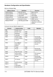
... Math coprocessor Hard disk driver Edge Edge Remarks Dynamically programmable Dynamically programmable PCI interrupt sharing Dynamically programmable PCI interrupt sharing Dynamically programmable PCI interrupt sharing 1-6 EXTENSA 700/710 Service Guide
... Math coprocessor Hard disk driver Edge Edge Remarks Dynamically programmable Dynamically programmable PCI interrupt sharing Dynamically programmable PCI interrupt sharing Dynamically programmable PCI interrupt sharing 1-6 EXTENSA 700/710 Service Guide

Service Guide
Page 12
... 60,75,85 60,75,85 60 60,75,85 Simultaneous 60 60 60 60 60 60 60 60 Simultaneous on TFT LCD SVGA Y Y Y Y Y Y Y Y 1-10 EXTENSA 700/710 Service Guide resolution (Ext. resolution (LCD) Max. Second-Level Cache Item SRAM voltage 1st level cache control 2st level cache control Cache scheme...
... 60,75,85 60,75,85 60 60,75,85 Simultaneous 60 60 60 60 60 60 60 60 Simultaneous on TFT LCD SVGA Y Y Y Y Y Y Y Y 1-10 EXTENSA 700/710 Service Guide resolution (Ext. resolution (LCD) Max. Second-Level Cache Item SRAM voltage 1st level cache control 2st level cache control Cache scheme...

Service Guide
Page 14
... Right side Yes*2 Yes Fax/Modem Item Chipset Fax modem data baud rate (bps) Data modem data baud rate (bps) Lucent 56K 56K Specification 1-12 EXTENSA 700/710 Service Guide
... Right side Yes*2 Yes Fax/Modem Item Chipset Fax modem data baud rate (bps) Data modem data baud rate (bps) Lucent 56K 56K Specification 1-12 EXTENSA 700/710 Service Guide

Service Guide
Page 16
... IDE compatible CD-DA, CD-ROM, CD-ROM XA (except ADPCM), CD-I, Photo CD (Multisession), Video CD, CD+ Soft eject (with emergency eject hole) 5 1-14 EXTENSA 700/710 Service Guide
... IDE compatible CD-DA, CD-ROM, CD-ROM XA (except ADPCM), CD-I, Photo CD (Multisession), Video CD, CD+ Soft eject (with emergency eject hole) 5 1-14 EXTENSA 700/710 Service Guide
Service Guide
Page 18
...) Display technology STN Resolution SVGA (800x600) Support colors - Specification IBM ITSV50D2 Hitachi TX34D62 12.1 13.3 TFT SVGA (800x600) 262,144 colors TFT XGA (1024x768) 1-16 EXTENSA 700/710 Service Guide
...) Display technology STN Resolution SVGA (800x600) Support colors - Specification IBM ITSV50D2 Hitachi TX34D62 12.1 13.3 TFT SVGA (800x600) 262,144 colors TFT XGA (1024x768) 1-16 EXTENSA 700/710 Service Guide

Service Guide
Page 20
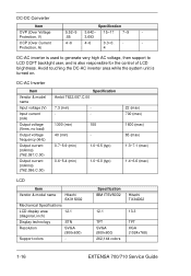
... Requirements Internal filter meets: FCC class B requirements. (USA) VDE 243/1991 class B requirements. (German) CISPR 22 Class B requirements. (Scandinavia) VCCI class II requirements. (Japan) 1-18 EXTENSA 700/710 Service Guide
... Requirements Internal filter meets: FCC class B requirements. (USA) VDE 243/1991 class B requirements. (German) CISPR 22 Class B requirements. (Scandinavia) VCCI class II requirements. (Japan) 1-18 EXTENSA 700/710 Service Guide

Service Guide
Page 21
System Utility C h a p t e r 2 BIOS The flash Memory Update: The flash memory update is being displayed. To activate the Setup Utility, press F2 during POST (while the Extensa logo is required for the following conditions: • New versions of system programs • New features or options Create a bootable diskette C:\Sys A: Copy flash utility & new versions BIOS to system. A:\plash 700-40.rom /mode=3 Note: mode=3, set DMI value to the diskette, then boot from diskette driver. Chapter 2 2-1
System Utility C h a p t e r 2 BIOS The flash Memory Update: The flash memory update is being displayed. To activate the Setup Utility, press F2 during POST (while the Extensa logo is required for the following conditions: • New versions of system programs • New features or options Create a bootable diskette C:\Sys A: Copy flash utility & new versions BIOS to system. A:\plash 700-40.rom /mode=3 Note: mode=3, set DMI value to the diskette, then boot from diskette driver. Chapter 2 2-1

Service Guide
Page 22
... Device: [Auto] Mic-In/Lin-in: [Line-In] System memory: 32 MB Video Memory: 2 MB CPU Type Pentium II CPU Speed 266 MHz VGA BIOS Version: V1.12.000.R01J BIOS Version: V1.0 R00M2F F1 Help Select Item Change Values F9 Setup Defaults Esc Exit Select Menu Enter... boot-up . When set to Auto, the computer automatically determines the display device. Boot Device Priority: Press Enter to both the computer 2-2 EXTENSA 700/710 Service Guide When set to Both, the computer outputs to access the Boot Device Priority submenu. Speaker: Enables or disables the internal...
... Device: [Auto] Mic-In/Lin-in: [Line-In] System memory: 32 MB Video Memory: 2 MB CPU Type Pentium II CPU Speed 266 MHz VGA BIOS Version: V1.12.000.R01J BIOS Version: V1.0 R00M2F F1 Help Select Item Change Values F9 Setup Defaults Esc Exit Select Menu Enter... boot-up . When set to Auto, the computer automatically determines the display device. Boot Device Priority: Press Enter to both the computer 2-2 EXTENSA 700/710 Service Guide When set to Both, the computer outputs to access the Boot Device Priority submenu. Speaker: Enables or disables the internal...

Service Guide
Page 24
... the serial port. Options: 3F8, 2F8, 3E8 or 2E8 Interrupt: Sets the interrupt request of the serial port. Options: ECP, Bi-directional or Output only 2-4 EXTENSA 700/710 Service Guide Options: IRQ4, IRQ10, IRQ11 or IRQ 3 Parallel Port: Mode: Sets the operation mode of the parallel port. Serial Port: Base I/O address...
... the serial port. Options: 3F8, 2F8, 3E8 or 2E8 Interrupt: Sets the interrupt request of the serial port. Options: ECP, Bi-directional or Output only 2-4 EXTENSA 700/710 Service Guide Options: IRQ4, IRQ10, IRQ11 or IRQ 3 Parallel Port: Mode: Sets the operation mode of the parallel port. Serial Port: Base I/O address...

Service Guide
Page 26
...: Enabled or Disabled Resume On Alarm: When enabled and the system resume date and time are making a presentation on your computer. Options: Disabled or Enabled 2-6 EXTENSA 700/710 Service Guide
...: Enabled or Disabled Resume On Alarm: When enabled and the system resume date and time are making a presentation on your computer. Options: Disabled or Enabled 2-6 EXTENSA 700/710 Service Guide
Service Guide
Page 28
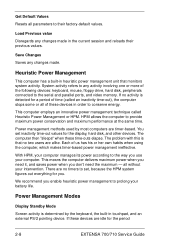
... to prolong your battery life. There are no two users are alike. Power Management Modes Display Standby Mode Screen activity is detected for the period 2-8 EXTENSA 700/710 Service Guide If no activity is determined by most computers are idle for a period of these devices in the current session and reloads...
... to prolong your battery life. There are no two users are alike. Power Management Modes Display Standby Mode Screen activity is detected for the period 2-8 EXTENSA 700/710 Service Guide If no activity is determined by most computers are idle for a period of these devices in the current session and reloads...
Service Guide
Page 30
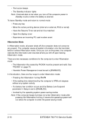
... • Move the active pointing device (internal or external, PS/2 or serial) • Have the Resume Timer set to enter the power-saving mode. 2-10 EXTENSA 700/710 Service Guide • The buzzer beeps • The Standby indicator lights Note: Unstored data is lost when you turn on page 73. •...
... • Move the active pointing device (internal or external, PS/2 or serial) • Have the Resume Timer set to enter the power-saving mode. 2-10 EXTENSA 700/710 Service Guide • The buzzer beeps • The Standby indicator lights Note: Unstored data is lost when you turn on page 73. •...
Service Guide
Page 32
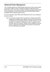
... standard designed to your Windows 95 user's manual. APM should be enabled to normal operation from Standby or Hibernation mode. Use APM whenever possible. 2-12 EXTENSA 700/710 Service Guide Note: If you enable heuristic power management in Setup without degrading performance. APM is a power-management approach defined jointly by default...
... standard designed to your Windows 95 user's manual. APM should be enabled to normal operation from Standby or Hibernation mode. Use APM whenever possible. 2-12 EXTENSA 700/710 Service Guide Note: If you enable heuristic power management in Setup without degrading performance. APM is a power-management approach defined jointly by default...

Service Guide
Page 36
... M Door A x 1 MODEM Door DIM M Board MODEM Board Lower Case L x3 J x 4 CPU H e at S in k H x 1 J x 4 FDD M od ule IM M M od ule H x 1 IM M S hie ld C x 2 Fan M ain Board EXTENSA 700/710 Service Guide LCD FPC C ab le LED C a ble Tou ch P ad P C M C IA Socker DC-DC & Charger Board ID E B oard
... M Door A x 1 MODEM Door DIM M Board MODEM Board Lower Case L x3 J x 4 CPU H e at S in k H x 1 J x 4 FDD M od ule IM M M od ule H x 1 IM M S hie ld C x 2 Fan M ain Board EXTENSA 700/710 Service Guide LCD FPC C ab le LED C a ble Tou ch P ad P C M C IA Socker DC-DC & Charger Board ID E B oard

Service Guide
Page 38
... the hard disk drive from its bezel. 3. To re-connect the hard disk cable, be sure that the 1st pin is aligned up as indicated. 3-4 EXTENSA 700/710 Service Guide To remove the internal hard disk drive, remove the screw with a flat-bladed screwdriver or a coin. 2. Disassembling the hard disk drive...
... the hard disk drive from its bezel. 3. To re-connect the hard disk cable, be sure that the 1st pin is aligned up as indicated. 3-4 EXTENSA 700/710 Service Guide To remove the internal hard disk drive, remove the screw with a flat-bladed screwdriver or a coin. 2. Disassembling the hard disk drive...

Service Guide
Page 40
Replace the middle cover. 5. Removing the keyboard 1. Lift the cover to release the latches. 3. The keyboard can be matched, then place it out. 2. Remove the middle cover by using a flat-bladed screwdriver to remove 4. Remove the hinge cover by releasing this connector. 3-6 EXTENSA 700/710 Service Guide Pull the keyboard up and outward to expose the keyboard connector at CN22. 7. The latches of the middle cover and the upper case must be removed by sliding it into position. 6.
Replace the middle cover. 5. Removing the keyboard 1. Lift the cover to release the latches. 3. The keyboard can be matched, then place it out. 2. Remove the middle cover by using a flat-bladed screwdriver to remove 4. Remove the hinge cover by releasing this connector. 3-6 EXTENSA 700/710 Service Guide Pull the keyboard up and outward to expose the keyboard connector at CN22. 7. The latches of the middle cover and the upper case must be removed by sliding it into position. 6.

Service Guide
Page 42
... cable at CN10 from the main board. Detach the touch pad cover from the upper case. 5. Remove the right channel speaker by removing it's 2 screws. 3-8 EXTENSA 700/710 Service Guide Remove the touch pad board from the left channel speaker at CN8 and the right channel speaker at CN17. 3. Disconnect the...
... cable at CN10 from the main board. Detach the touch pad cover from the upper case. 5. Remove the right channel speaker by removing it's 2 screws. 3-8 EXTENSA 700/710 Service Guide Remove the touch pad board from the left channel speaker at CN8 and the right channel speaker at CN17. 3. Disconnect the...

Service Guide
Page 44
Remove the IDE card from the main board at CN30. 4. Disassembling the lower case: 1. Remove the 4 screws on the PCMCIA card. 5. Lift the PCMCIA card from the main board at CN16. 6. This completes the disassembly procedure of the lower case. 3-10 EXTENSA 700/710 Service Guide Remove the main board from the main board at CN24 and CN21. 3. Disconnect the DC-DC charger board from the lower case. 2.
Remove the IDE card from the main board at CN30. 4. Disassembling the lower case: 1. Remove the 4 screws on the PCMCIA card. 5. Lift the PCMCIA card from the main board at CN16. 6. This completes the disassembly procedure of the lower case. 3-10 EXTENSA 700/710 Service Guide Remove the main board from the main board at CN24 and CN21. 3. Disconnect the DC-DC charger board from the lower case. 2.


