
Intel Smart Response Installation Guide
Page 1
... Icon tray, lower right-hand corner of the screen. 4. For the new version RST driver, please check our website for the latest information: http://www.asrock.com * Before you use the full SSD as Cache device or only 20GB, and if you just need to set the UEFI option "SATA Mode..." mode. 7. Boot system to [RAID Mode]. For all required drivers, including RST storage driver version 10.5 or later. 2. Intel Smart Response Technology Installation Guide This motherboard supports Intel Smart Response Technology.
... Icon tray, lower right-hand corner of the screen. 4. For the new version RST driver, please check our website for the latest information: http://www.asrock.com * Before you use the full SSD as Cache device or only 20GB, and if you just need to set the UEFI option "SATA Mode..." mode. 7. Boot system to [RAID Mode]. For all required drivers, including RST storage driver version 10.5 or later. 2. Intel Smart Response Technology Installation Guide This motherboard supports Intel Smart Response Technology.
RAID Installation Guide
Page 2
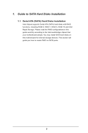
This section will guide you how to the Intel southbridge chipset that your motherboard adopts. You may install SATA hard disks on this guide carefully according to create RAID on SATA ports. 2 1. Please read the RAID configurations in this motherboard for internal storage devices. Guide to SATA Hard Disks Installation 1.1 Serial ATA (SATA) Hard Disks Installation Intel chipset supports Serial ATA (SATA) hard disks with RAID functions, including RAID 0, RAID 1, RAID 5, RAID 10 and Intel Rapid Storage.
This section will guide you how to the Intel southbridge chipset that your motherboard adopts. You may install SATA hard disks on this guide carefully according to create RAID on SATA ports. 2 1. Please read the RAID configurations in this motherboard for internal storage devices. Guide to SATA Hard Disks Installation 1.1 Serial ATA (SATA) Hard Disks Installation Intel chipset supports Serial ATA (SATA) hard disks with RAID functions, including RAID 0, RAID 1, RAID 5, RAID 10 and Intel Rapid Storage.
RAID Installation Guide
Page 3
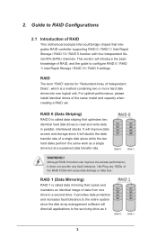
... The term "RAID" stands for "Redundant Array of the same model and capacity when creating a RAID set. Guide to RAID Configurations 2.1 Introduction of RAID This motherboard adopts Intel southbridge chipset that copies and maintains an identical image of RAID, and the guide to the surviving drive as a single drive but at...
... The term "RAID" stands for "Redundant Array of the same model and capacity when creating a RAID set. Guide to RAID Configurations 2.1 Introduction of RAID This motherboard adopts Intel southbridge chipset that copies and maintains an identical image of RAID, and the guide to the surviving drive as a single drive but at...
RAID Installation Guide
Page 18
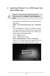
... steps below. STEP 1: Copy Intel® RAID drivers into a USB flash disk You can download the drivers from ASRock's website and unzip the files into a USB flash disk or copy the files from ASRock's motherboard support CD. (Please copy the files under the following directory: 32 bit: ..\i386\Win7_Intel.. 64-bit: ..\AMD64\Win7...
... steps below. STEP 1: Copy Intel® RAID drivers into a USB flash disk You can download the drivers from ASRock's website and unzip the files into a USB flash disk or copy the files from ASRock's motherboard support CD. (Please copy the files under the following directory: 32 bit: ..\i386\Win7_Intel.. 64-bit: ..\AMD64\Win7...
RAID Installation Guide
Page 20
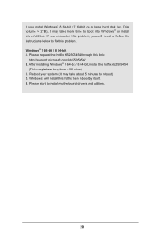
... to reboot.) D. Please request the hotfix KB2505454 through this hotfix then reboot by itself. Windows® will need to follow the instructions below to install motherboard drivers and utilities. 20 If you encounter this problem, you install Windows® 8 64-bit / 7 64-bit on a large hard disk (ex. Disk volume > 2TB...
... to reboot.) D. Please request the hotfix KB2505454 through this hotfix then reboot by itself. Windows® will need to follow the instructions below to install motherboard drivers and utilities. 20 If you encounter this problem, you install Windows® 8 64-bit / 7 64-bit on a large hard disk (ex. Disk volume > 2TB...

Intel Rapid Storage Guide
Page 12
..., a RAID volume must be created, and the F6 installation method must be used to enable RAID in System BIOS Use the instructions included with your motherboard to load the Intel® Rapid Storage Technology driver during POST, press Ctrl and i at the same time to enter the option ROM user interface...
..., a RAID volume must be created, and the F6 installation method must be used to enable RAID in System BIOS Use the instructions included with your motherboard to load the Intel® Rapid Storage Technology driver during POST, press Ctrl and i at the same time to enter the option ROM user interface...

User Manual
Page 2
..."Perchlorate Material-special handling may appear in Perchlorate Best Management Practices (BMP) regulations passed by ASRock. Copyright Notice: No part of this documentation, ASRock does not provide warranty of any kind, either expressed or implied, including but not limited ... including interference that may apply, see www.dtsc.ca.gov/hazardouswaste/ perchlorate" ASRock Website: http://www.asrock.com CALIFORNIA, USA ONLY The Lithium battery adopted on this motherboard contains Perchlorate, a toxic substance controlled in this documentation are trademarks or registered trademarks...
..."Perchlorate Material-special handling may appear in Perchlorate Best Management Practices (BMP) regulations passed by ASRock. Copyright Notice: No part of this documentation, ASRock does not provide warranty of any kind, either expressed or implied, including but not limited ... including interference that may apply, see www.dtsc.ca.gov/hazardouswaste/ perchlorate" ASRock Website: http://www.asrock.com CALIFORNIA, USA ONLY The Lithium battery adopted on this motherboard contains Perchlorate, a toxic substance controlled in this documentation are trademarks or registered trademarks...

User Manual
Page 3
Contents Chapter 1 Introduction 1 1.1 Package Contents 1 1.2 Specifications 2 1.3 Unique Features 6 1.4 Motherboard Layout 10 1.5 I/O Panel 12 Chapter 2 Installation 14 2.1 Installing the CPU 15 2.2 Installing the CPU Fan and Heatsink 18 2.3 Installing Memory Modules (DIMM) 19 2.4 Expansion Slots (...
Contents Chapter 1 Introduction 1 1.1 Package Contents 1 1.2 Specifications 2 1.3 Unique Features 6 1.4 Motherboard Layout 10 1.5 I/O Panel 12 Chapter 2 Installation 14 2.1 Installing the CPU 15 2.2 Installing the CPU Fan and Heatsink 18 2.3 Installing Memory Modules (DIMM) 19 2.4 Expansion Slots (...
User Manual
Page 6
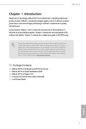
...://www.asrock.com. 1.1 Package Contents • ASRock Z87 Pro4 Motherboard (ATX Form Factor) • ASRock Z87 Pro4 Quick Installation Guide • ASRock Z87 Pro4 Support CD • 2 x Serial ATA (SATA) Data Cables (Optional) • 1 x I/O Panel Shield 1 English In case any modifications of this manual, Chapter 1 and 2 contains the introduction of this motherboard, please visit our website for purchasing ASRock Z87 Pro4 motherboard, a reliable motherboard produced under ASRock's consistently...
...://www.asrock.com. 1.1 Package Contents • ASRock Z87 Pro4 Motherboard (ATX Form Factor) • ASRock Z87 Pro4 Quick Installation Guide • ASRock Z87 Pro4 Support CD • 2 x Serial ATA (SATA) Data Cables (Optional) • 1 x I/O Panel Shield 1 English In case any modifications of this manual, Chapter 1 and 2 contains the introduction of this motherboard, please visit our website for purchasing ASRock Z87 Pro4 motherboard, a reliable motherboard produced under ASRock's consistently...

User Manual
Page 12
...bypassing OMG, guest accounts without entering Windows® OS. ASRock Crashless BIOS ASRock Crashless BIOS allows users to establish an internet curfew or restrict internet access at specified times via OMG. Z87 Pro4 ASRock XFast RAM ASRock XFast RAM is that cannot be placed in the root ...directory of your USB disk. If power loss occurs during the BIOS updating process, ASRock Crashless BIOS will power on automatically to dampness by enabling "Dehumidifier Function". You may prevent motherboard ...
...bypassing OMG, guest accounts without entering Windows® OS. ASRock Crashless BIOS ASRock Crashless BIOS allows users to establish an internet curfew or restrict internet access at specified times via OMG. Z87 Pro4 ASRock XFast RAM ASRock XFast RAM is that cannot be placed in the root ...directory of your USB disk. If power loss occurs during the BIOS updating process, ASRock Crashless BIOS will power on automatically to dampness by enabling "Dehumidifier Function". You may prevent motherboard ...

User Manual
Page 13
... precious time everyday typing usernames to windows automatically! 8 English The unprecedented UEFI provides a more attractive interface and more waiting! This motherboard also provides a free 3.5mm audio cable (optional) that ensures users the most convenient computing environment. Why should we even bother ... when the system is a blend of system configuration tools, cool sound effects and stunning visuals. ASRock Interactive UEFI ASRock Interactive UEFI is powered on the PC. ASRock Restart to UEFI allows users to Windows? The speedy boot will enter the UEFI directly after you...
... precious time everyday typing usernames to windows automatically! 8 English The unprecedented UEFI provides a more attractive interface and more waiting! This motherboard also provides a free 3.5mm audio cable (optional) that ensures users the most convenient computing environment. Why should we even bother ... when the system is a blend of system configuration tools, cool sound effects and stunning visuals. ASRock Interactive UEFI ASRock Interactive UEFI is powered on the PC. ASRock Restart to UEFI allows users to Windows? The speedy boot will enter the UEFI directly after you...

User Manual
Page 14
The fans will be able to power your PC from our support CD, Easy Driver Installer is a handy tool in A-Tuning. Z87 Pro4 ASRock Home Cloud This motherboard supports remote wake with the onboard Intel LAN, so you can connect with your PC on or turn it off, monitor and take ... storage device, then downloads and installs the other required drivers automatically. 9 English Configure up to install the drivers from anywhere in the world. ASRock Easy Driver Installer For users that installs the LAN driver to the next speed level when the assigned temperature is included in the UEFI that...
The fans will be able to power your PC from our support CD, Easy Driver Installer is a handy tool in A-Tuning. Z87 Pro4 ASRock Home Cloud This motherboard supports remote wake with the onboard Intel LAN, so you can connect with your PC on or turn it off, monitor and take ... storage device, then downloads and installs the other required drivers automatically. 9 English Configure up to install the drivers from anywhere in the world. ASRock Easy Driver Installer For users that installs the LAN driver to the next speed level when the assigned temperature is included in the UEFI that...

User Manual
Page 15
1.4 Motherboard Layout 1 2 34 56 USB 2.0 T: USB0 B: USB1 ... USB3 Top: RJ-45 7 ATXPWR1 Top: 1 1 USB3_6_7 Front USB 3.0 Central/Bass LINE IN Center: REAR SPK Bottom: Optical SPDIF Z87 Pro4 CHA_FAN2 USB3_8 Vertical Type A USB 3.0 Top: Center: FRONT Bottom: MIC IN USB3_4_5 PCI Express 3.0 8 29 PCIE1 LAN X X X ...Fast LAN Fast USB Fast RAM 9 10 CMOS Battery PCIE2 Super I/O PCIE4 PCIE3 RoHS Intel Z87 Audio CODEC HD_AUDIO1 SPDIF1_OUT1 1 1 1 TPMS1 PCI1 PCI2 COM1 1 IR1 1 CLRCMOS1 1 USB6_7 1 USB4_5 1 SATA3_0 SATA3_2 SATA3_4 SATA3_1...
1.4 Motherboard Layout 1 2 34 56 USB 2.0 T: USB0 B: USB1 ... USB3 Top: RJ-45 7 ATXPWR1 Top: 1 1 USB3_6_7 Front USB 3.0 Central/Bass LINE IN Center: REAR SPK Bottom: Optical SPDIF Z87 Pro4 CHA_FAN2 USB3_8 Vertical Type A USB 3.0 Top: Center: FRONT Bottom: MIC IN USB3_4_5 PCI Express 3.0 8 29 PCIE1 LAN X X X ...Fast LAN Fast USB Fast RAM 9 10 CMOS Battery PCIE2 Super I/O PCIE4 PCIE3 RoHS Intel Z87 Audio CODEC HD_AUDIO1 SPDIF1_OUT1 1 1 1 TPMS1 PCI1 PCI2 COM1 1 IR1 1 CLRCMOS1 1 USB6_7 1 USB4_5 1 SATA3_0 SATA3_2 SATA3_4 SATA3_1...

User Manual
Page 19
.... • Hold components by the edges and do not touch the ICs. • Whenever you install motherboard components or change any motherboard settings. • Make sure to the chassis, please do so may damage the motherboard. Failure to do not overtighten the screws! Doing so may cause physical injuries to you and damages...
.... • Hold components by the edges and do not touch the ICs. • Whenever you install motherboard components or change any motherboard settings. • Make sure to the chassis, please do so may damage the motherboard. Failure to do not overtighten the screws! Doing so may cause physical injuries to you and damages...

User Manual
Page 22
The cover must be placed if you wish to return the motherboard for after service. 17 English Z87 Pro4 Please save and replace the cover if the processor is removed.
The cover must be placed if you wish to return the motherboard for after service. 17 English Z87 Pro4 Please save and replace the cover if the processor is removed.

User Manual
Page 24
... The DIMM only fits in one or three memory module installed. 3. It is unable to activate Dual Channel Memory Technology with only one correct orientation. Z87 Pro4 2.3 Installing Memory Modules (DIMM) This motherboard provides four 240-pin DDR3 (Double Data Rate 3) DIMM slots, and supports Dual Channel Memory Technology. 1.
... The DIMM only fits in one or three memory module installed. 3. It is unable to activate Dual Channel Memory Technology with only one correct orientation. Z87 Pro4 2.3 Installing Memory Modules (DIMM) This motherboard provides four 240-pin DDR3 (Double Data Rate 3) DIMM slots, and supports Dual Channel Memory Technology. 1.

User Manual
Page 26
... The PCI1 and PCI2 slots are 2 PCI slots and 4 PCI Express slots on the motherboard. PCIe slots: PCIE1 (PCIe 3.0 x16 slot) is used for PCI Express x1 lane width cards. Z87 Pro4 2.4 Expansion Slots (PCI and PCI Express Slots) There are used for PCI Express x16 ...lane width graphics cards. PCIE4 (PCIe 2.0 x1 slot) is used to the motherboard's chassis fan connector (CHA_FAN1 or CHA_FAN2) when using multiple graphics...
... The PCI1 and PCI2 slots are 2 PCI slots and 4 PCI Express slots on the motherboard. PCIe slots: PCIE1 (PCIe 3.0 x16 slot) is used for PCI Express x1 lane width cards. Z87 Pro4 2.4 Expansion Slots (PCI and PCI Express Slots) There are used for PCI Express x16 ...lane width graphics cards. PCIE4 (PCIe 2.0 x1 slot) is used to the motherboard's chassis fan connector (CHA_FAN1 or CHA_FAN2) when using multiple graphics...

User Manual
Page 28
Do NOT place jumper caps over the headers and connectors will cause permanent damage to the motherboard. Note the positive and negative pins before connecting the cables. The LED is on when the hard drive is operating. You may differ by chassis. ... off (S5). English 23 The LED keeps blinking when the system is in S1/S3 sleep state. When connecting your system using the power switch. Z87 Pro4 2.6 Onboard Headers and Connectors Onboard headers and connectors are matched correctly. System Panel Header (9-pin PANEL1) (see p.10, No. 16) PLED+ PLEDPWRBTN# GND 1 GND RESET...
Do NOT place jumper caps over the headers and connectors will cause permanent damage to the motherboard. Note the positive and negative pins before connecting the cables. The LED is on when the hard drive is operating. You may differ by chassis. ... off (S5). English 23 The LED keeps blinking when the system is in S1/S3 sleep state. When connecting your system using the power switch. Z87 Pro4 2.6 Onboard Headers and Connectors Onboard headers and connectors are matched correctly. System Panel Header (9-pin PANEL1) (see p.10, No. 16) PLED+ PLEDPWRBTN# GND 1 GND RESET...

User Manual
Page 29
...IntA_PB_SSTXIntA_PB_SSTX+ GND IntA_PB_DIntA_PB_D+ Dummy 1 Besides four USB 3.0 ports on the I /O panel, there are two headers and one port on this header to this motherboard. English 24 Power LED Header (3-pin PLED1) (see p.10, No. 14) SATA3_2 SATA3_3 SATA3_4 SATA3_5 These six SATA3 connectors support SATA data cables for ...(USB3_8) (see p.10, No. 22) USB_PWR PP+ GND DUMMY 1 GND P+ PUSB_PWR Besides four USB 2.0 ports on the I /O panel, there are two headers on this motherboard. PLED+ PLED+ Please connect the chassis power LED to indicate the system's power status.
...IntA_PB_SSTXIntA_PB_SSTX+ GND IntA_PB_DIntA_PB_D+ Dummy 1 Besides four USB 3.0 ports on the I /O panel, there are two headers and one port on this header to this motherboard. English 24 Power LED Header (3-pin PLED1) (see p.10, No. 14) SATA3_2 SATA3_3 SATA3_4 SATA3_5 These six SATA3 connectors support SATA data cables for ...(USB3_8) (see p.10, No. 22) USB_PWR PP+ GND DUMMY 1 GND P+ PUSB_PWR Besides four USB 2.0 ports on the I /O panel, there are two headers on this motherboard. PLED+ PLED+ Please connect the chassis power LED to indicate the system's power status.

User Manual
Page 31
...) (see p.10, No. 24) Serial Port Header (9-pin COM1) (see p.10, No. 4) GND +12V FAN_SPEED FAN_SPEED_CONTROL GND +12V FAN_SPEED This motherboard provides a 4-Pin CPU fan (Quiet Fan) connector. To use a 20-pin ATX power supply, please plug it to Pin 1-3. English 26 This header... supports an optional wireless transmitting and receiving infrared module. This motherboard provides an 8-pin ATX 12V power connector. (3-pin PWR_FAN1) (see p.10, No. 1) CPU Fan Connectors (4-pin CPU_FAN1) (see p.10, No. ...
...) (see p.10, No. 24) Serial Port Header (9-pin COM1) (see p.10, No. 4) GND +12V FAN_SPEED FAN_SPEED_CONTROL GND +12V FAN_SPEED This motherboard provides a 4-Pin CPU fan (Quiet Fan) connector. To use a 20-pin ATX power supply, please plug it to Pin 1-3. English 26 This header... supports an optional wireless transmitting and receiving infrared module. This motherboard provides an 8-pin ATX 12V power connector. (3-pin PWR_FAN1) (see p.10, No. 1) CPU Fan Connectors (4-pin CPU_FAN1) (see p.10, No. ...

