
Intel Smart Response Installation Guide
Page 1
...you want to use RST function, you just need to set the UEFI option "SATA Mode" to [RAID Mode]. Complete initial system setup, including installing the OS to build RAID 0 or RAID 1 in system at this point! 3. When pop-up menu appears, chose which SSD you wish ...Menu or by step instructions below. Intel Smart Response Technology Installation Guide This motherboard supports Intel Smart Response Technology. UI setup instruction: 1. For the new version RST driver, please check our website for the latest information: http://www.asrock.com * Before you use the full SSD as Cache ...
...you want to use RST function, you just need to set the UEFI option "SATA Mode" to [RAID Mode]. Complete initial system setup, including installing the OS to build RAID 0 or RAID 1 in system at this point! 3. When pop-up menu appears, chose which SSD you wish ...Menu or by step instructions below. Intel Smart Response Technology Installation Guide This motherboard supports Intel Smart Response Technology. UI setup instruction: 1. For the new version RST driver, please check our website for the latest information: http://www.asrock.com * Before you use the full SSD as Cache ...
User Manual
Page 4
... 1 Introduction 1 1.1 Package Contents 1 1.2 Specifications 2 1.3 Unique Features 7 1.4 Motherboard Layout 11 1.5 I/O Panel 15 1.6 WiFi-802.11n Module and ASRock WiFi 2.4GHz Antenna (for Z87 OC Formula/ac only ) 17 Chapter 2 Installation 20 2.1 Installing the CPU 21 2.2 Installing the CPU Fan and Heatsink 24 2.3 Installing Memory Modules (DIMM) 25 2.4 Expansion Slots (PCI and PCI Express Slots) 27 2.5 Jumpers Setup 28 2.6 Onboard...
... 1 Introduction 1 1.1 Package Contents 1 1.2 Specifications 2 1.3 Unique Features 7 1.4 Motherboard Layout 11 1.5 I/O Panel 15 1.6 WiFi-802.11n Module and ASRock WiFi 2.4GHz Antenna (for Z87 OC Formula/ac only ) 17 Chapter 2 Installation 20 2.1 Installing the CPU 21 2.2 Installing the CPU Fan and Heatsink 24 2.3 Installing Memory Modules (DIMM) 25 2.4 Expansion Slots (PCI and PCI Express Slots) 27 2.5 Jumpers Setup 28 2.6 Onboard...
User Manual
Page 5
..., 3-Way CrossFireXTM and Quad CrossFireXTM Operation Guide 49 2.13.1 Installing Two CrossFireXTM-Ready Graphics Cards 49 2.13.2 Installing Three CrossFireXTM-Ready Graphics Cards 50 2.13.3 Installing Four CrossFireXTM-Ready Graphics Cards 51 2.13.4 Driver Installation and Setup 52 Chapter 3 Software and Utilities Operation 53 3.1 Installing Drivers 53 3.2 Formula Drive 54 3.3 Intel® Rapid Start Technology 58...
..., 3-Way CrossFireXTM and Quad CrossFireXTM Operation Guide 49 2.13.1 Installing Two CrossFireXTM-Ready Graphics Cards 49 2.13.2 Installing Three CrossFireXTM-Ready Graphics Cards 50 2.13.3 Installing Four CrossFireXTM-Ready Graphics Cards 51 2.13.4 Driver Installation and Setup 52 Chapter 3 Software and Utilities Operation 53 3.1 Installing Drivers 53 3.2 Formula Drive 54 3.3 Intel® Rapid Start Technology 58...
User Manual
Page 7
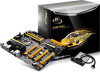
... guide of the software and utilities. ASRock website http://www.asrock.com. 1.1 Package Contents • ASRock Z87 OC Formula/ac / Z87 OC Formula Motherboard (EATX Form Factor) • ASRock Z87 OC Formula/ac / Z87 OC Formula Quick Installation Guide • ASRock Z87 OC Formula/ac / Z87 OC Formula Support CD • 10 x Serial ATA (SATA) Data Cables (Optional) • 2 x SATA 1 to 1 Power Cables (Optional) • 1 x I/O Panel Shield • 1 x ASRock Flexible SLI Bridge Connector Cable •...
... guide of the software and utilities. ASRock website http://www.asrock.com. 1.1 Package Contents • ASRock Z87 OC Formula/ac / Z87 OC Formula Motherboard (EATX Form Factor) • ASRock Z87 OC Formula/ac / Z87 OC Formula Quick Installation Guide • ASRock Z87 OC Formula/ac / Z87 OC Formula Support CD • 10 x Serial ATA (SATA) Data Cables (Optional) • 2 x SATA 1 to 1 Power Cables (Optional) • 1 x I/O Panel Shield • 1 x ASRock Flexible SLI Bridge Connector Cable •...

User Manual
Page 13
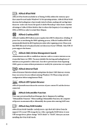
...game's priority higher, it can watch Youtube HD videos and download simultaneously. ASRock XFast USB ASRock XFast USB can easily recognize which includes the benefits listed below. Z87 OC Formula/ac / Z87 OC Formula 1.3 Unique Features ASRock Formula Drive Formula Drive is a BIOS flash utility embedded in Flash ROM. Just save the... and even supports continuous charging when your USB storage and launch this tool by installing the ASRock APP Charger makes your iPhone/iPad/iPod Touch charge up to access ASRock Instant Flash. Traffic Shaping: You can lower the latency in a few clicks ...
...game's priority higher, it can watch Youtube HD videos and download simultaneously. ASRock XFast USB ASRock XFast USB can easily recognize which includes the benefits listed below. Z87 OC Formula/ac / Z87 OC Formula 1.3 Unique Features ASRock Formula Drive Formula Drive is a BIOS flash utility embedded in Flash ROM. Just save the... and even supports continuous charging when your USB storage and launch this tool by installing the ASRock APP Charger makes your iPhone/iPad/iPod Touch charge up to access ASRock Instant Flash. Traffic Shaping: You can lower the latency in a few clicks ...
User Manual
Page 14
... Dehumidifier Function, the computer will automatically finish the BIOS update procedure after entering S4/S5 state. ASRock Easy RAID Installer ASRock Easy RAID Installer can start installing the OS in A-Tuning. Only USB 2.0 ports support this feature. ASRock Crashless BIOS ASRock Crashless BIOS allows users to your USB storage device, please change "SATA Mode" to extend their...
... Dehumidifier Function, the computer will automatically finish the BIOS update procedure after entering S4/S5 state. ASRock Easy RAID Installer ASRock Easy RAID Installer can start installing the OS in A-Tuning. Only USB 2.0 ports support this feature. ASRock Crashless BIOS ASRock Crashless BIOS allows users to your USB storage device, please change "SATA Mode" to extend their...
User Manual
Page 15
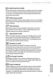
... 1.5 seconds to logon to Windows 8 from our support CD, Easy Driver Installer is a handy tool in ASRock UEFI Setup Utility. By enabling this motherboard instantly. Z87 OC Formula/ac / Z87 OC Formula ASRock Easy Driver Installer For users that don't have to waste time on the PC. No more... waiting! NickShih's OC Profile Have you different levels of Nick's secret recipe for overclockers who wish to ...
... 1.5 seconds to logon to Windows 8 from our support CD, Easy Driver Installer is a handy tool in ASRock UEFI Setup Utility. By enabling this motherboard instantly. Z87 OC Formula/ac / Z87 OC Formula ASRock Easy Driver Installer For users that don't have to waste time on the PC. No more... waiting! NickShih's OC Profile Have you different levels of Nick's secret recipe for overclockers who wish to ...
User Manual
Page 24
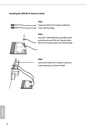
Then attach the SMA Wi-Fi Antenna Cables to the antenna ports on the motherboard's mini-PCIe slot. Installing the SMA Wi-Fi Antenna Cables Step 1 Prepare the SMA Wi-Fi Antenna Cables that is installed on the I/O shield 18 English Step 2 Locate the WiFi Module that come with the package. Step3 Insert the RP-SMA Wi-Fi Antenna Connectors to the WiFi Module.
Then attach the SMA Wi-Fi Antenna Cables to the antenna ports on the motherboard's mini-PCIe slot. Installing the SMA Wi-Fi Antenna Cables Step 1 Prepare the SMA Wi-Fi Antenna Cables that is installed on the I/O shield 18 English Step 2 Locate the WiFi Module that come with the package. Step3 Insert the RP-SMA Wi-Fi Antenna Connectors to the WiFi Module.
User Manual
Page 26
... components or change any components, place them on a carpet. Pre-installation Precautions Take note of the following precautions before you and damages to motherboard components. • In order to avoid damage from static electricity to unplug ...the power cord before you handle the components. • Hold components by the edges and do not touch the ICs. • Whenever you install the motherboard, study the configuration of your motherboard directly on a grounded anti-static pad or in the bag that comes with the components. • When...
... components or change any components, place them on a carpet. Pre-installation Precautions Take note of the following precautions before you and damages to motherboard components. • In order to avoid damage from static electricity to unplug ...the power cord before you handle the components. • Hold components by the edges and do not touch the ICs. • Whenever you install the motherboard, study the configuration of your motherboard directly on a grounded anti-static pad or in the bag that comes with the components. • When...

User Manual
Page 27
Otherwise, the CPU will be seriously damaged. 2. Before you insert the 1150-Pin CPU into the socket if above situation is unclean, or if there are any bent pins in the socket. Unplug all power cables before installing the CPU. 1 A B 2 21 English Z87 OC Formula/ac / Z87 OC Formula 2.1 Installing the CPU 1. Do not force to insert the CPU into the socket, please check if the PnP cap is on the socket, if the CPU surface is found.
Otherwise, the CPU will be seriously damaged. 2. Before you insert the 1150-Pin CPU into the socket if above situation is unclean, or if there are any bent pins in the socket. Unplug all power cables before installing the CPU. 1 A B 2 21 English Z87 OC Formula/ac / Z87 OC Formula 2.1 Installing the CPU 1. Do not force to insert the CPU into the socket, please check if the PnP cap is on the socket, if the CPU surface is found.

User Manual
Page 30
2.2 Installing the CPU Fan and Heatsink 1 24 2 CPU_FAN English
2.2 Installing the CPU Fan and Heatsink 1 24 2 CPU_FAN English
User Manual
Page 31
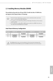
... into a DDR3 slot; It will cause permanent damage to the motherboard and the DIMM if you always need to install a DDR or DDR2 memory module into the slot at incorrect orientation. Z87 OC Formula/ac / Z87 OC Formula 2.3 Installing Memory Modules (DIMM) This motherboard provides four 240-pin DDR3 (Double Data Rate 3) DIMM slots, and supports Dual Channel...
... into a DDR3 slot; It will cause permanent damage to the motherboard and the DIMM if you always need to install a DDR or DDR2 memory module into the slot at incorrect orientation. Z87 OC Formula/ac / Z87 OC Formula 2.3 Installing Memory Modules (DIMM) This motherboard provides four 240-pin DDR3 (Double Data Rate 3) DIMM slots, and supports Dual Channel...
User Manual
Page 33
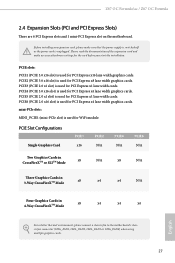
...lane width graphics cards. mini-PCIe slots: MINI_PCIE1 (mini-PCIe slot) is used for PCI Express x4 lane width graphics cards. Z87 OC Formula/ac / Z87 OC Formula 2.4 Expansion Slots (PCI and PCI Express Slots) There are 6 PCI Express slots and 1 mini-PCI Express slot on the ...chassis fan to the motherboard's chassis fan connector (CHA_FAN1, CHA_FAN2, CHA_FAN3 or CHA_FAN4) when using multiple graphics cards. 27 Before installing an expansion card, please make necessary hardware settings for PCI Express x16 lane width graphics cards. Please read the documentation of the...
...lane width graphics cards. mini-PCIe slots: MINI_PCIE1 (mini-PCIe slot) is used for PCI Express x4 lane width graphics cards. Z87 OC Formula/ac / Z87 OC Formula 2.4 Expansion Slots (PCI and PCI Express Slots) There are 6 PCI Express slots and 1 mini-PCI Express slot on the ...chassis fan to the motherboard's chassis fan connector (CHA_FAN1, CHA_FAN2, CHA_FAN3 or CHA_FAN4) when using multiple graphics cards. 27 Before installing an expansion card, please make necessary hardware settings for PCI Express x16 lane width graphics cards. Please read the documentation of the...
User Manual
Page 37
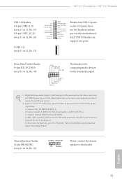
...follow the instructions in the Realtek Control panel and adjust "Recording Volume". You don't need to connect them for connecting audio devices to function correctly. Z87 OC Formula/ac / Z87 OC Formula USB 3.0 Headers (19-pin USB3_8_9) (see p.11 or 12, No. 15) (19-pin USB3_10_11) (see p.11 or 12, No.... Chassis Speaker Header (4-pin SPEAKER1) (see p.11 or 12, No. 25) DUMMY SPEAKER 1 +5V DUMMY Please connect the chassis speaker to install your system. 2. To activate the front mic, go to the "FrontMic" Tab in our manual and chassis manual to this motherboard. Connect Audio_R...
...follow the instructions in the Realtek Control panel and adjust "Recording Volume". You don't need to connect them for connecting audio devices to function correctly. Z87 OC Formula/ac / Z87 OC Formula USB 3.0 Headers (19-pin USB3_8_9) (see p.11 or 12, No. 15) (19-pin USB3_10_11) (see p.11 or 12, No.... Chassis Speaker Header (4-pin SPEAKER1) (see p.11 or 12, No. 25) DUMMY SPEAKER 1 +5V DUMMY Please connect the chassis speaker to install your system. 2. To activate the front mic, go to the "FrontMic" Tab in our manual and chassis manual to this motherboard. Connect Audio_R...
User Manual
Page 39
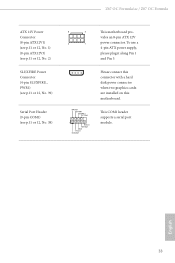
...#1 GND TTXD1 DDCD#1 Please connect this connector with a hard disk power connector when two graphics cards are installed on this motherboard. To use a 4-pin ATX power supply, please plug it along Pin 1 and Pin 5. Z87 OC Formula/ac / Z87 OC Formula ATX 12V Power Connector (8-pin ATX12V1) (see p.11 or 12, No. 1) (8-pin ATX12V3) (see p.11 or...
...#1 GND TTXD1 DDCD#1 Please connect this connector with a hard disk power connector when two graphics cards are installed on this motherboard. To use a 4-pin ATX power supply, please plug it along Pin 1 and Pin 5. Z87 OC Formula/ac / Z87 OC Formula ATX 12V Power Connector (8-pin ATX12V1) (see p.11 or 12, No. 1) (8-pin ATX12V3) (see p.11 or...
User Manual
Page 42
... cards. 1. When one just with Liquid Nitrogen. Users may refer to the BIOS LEDs (BIOS_A_LED or BIOS_B_LED) to find out the faulty one of the installed PCIE x16 cards is for debug only. PCIe ON/OFF Switch (SWITCH1) (see p.11 or 12, No. 18) 36 The LN2 mode aids in eliminating...
... cards. 1. When one just with Liquid Nitrogen. Users may refer to the BIOS LEDs (BIOS_A_LED or BIOS_B_LED) to find out the faulty one of the installed PCIE x16 cards is for debug only. PCIe ON/OFF Switch (SWITCH1) (see p.11 or 12, No. 18) 36 The LN2 mode aids in eliminating...
User Manual
Page 44
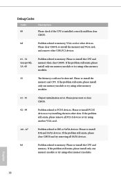
... the problem still exists, please clear CMOS and try using other slots. English 38 Debug Codes Code Description 00 Please check if the CPU is installed correctly and then clear CMOS. 0d Problem related to memory, VGA card or other USB, PCI devices. 01 - 54 (except 0d), 5A- 60 ...one memory module or try using other memory modules. 61 - 91 Chipset initialization error. A7 Problem related to PCI-E devices. Please clear CMOS, re-install the memory and VGA card, and remove other devices. Please press reset or clear CMOS. 92 - 99 Problem related to IDE or SATA devices....
... the problem still exists, please clear CMOS and try using other slots. English 38 Debug Codes Code Description 00 Please check if the CPU is installed correctly and then clear CMOS. 0d Problem related to memory, VGA card or other USB, PCI devices. 01 - 54 (except 0d), 5A- 60 ...one memory module or try using other memory modules. 61 - 91 Chipset initialization error. A7 Problem related to PCI-E devices. Please clear CMOS, re-install the memory and VGA card, and remove other devices. Please press reset or clear CMOS. 92 - 99 Problem related to IDE or SATA devices....

User Manual
Page 45
...d8 Invalid Password. FF Please check if the CPU is installed correctly and then clear CMOS. Please try re-installing the VGA card. If the problem still exists, please install only one memory module or try installing the VGA card in other slots or use other memory modules... other VGA cards. English 39 Please re-install the CPU and memory then clear CMOS. Please try re-installing the keyboard and mouse. b7 Problem related to USB devices. d6 The VGA could not be recognized. Z87 OC Formula/ac / Z87 OC Formula b4 Problem related to memory. d7 The Keyboard...
...d8 Invalid Password. FF Please check if the CPU is installed correctly and then clear CMOS. Please try re-installing the VGA card. If the problem still exists, please install only one memory module or try installing the VGA card in other slots or use other memory modules... other VGA cards. English 39 Please re-install the CPU and memory then clear CMOS. Please try re-installing the keyboard and mouse. b7 Problem related to USB devices. d6 The VGA could not be recognized. Z87 OC Formula/ac / Z87 OC Formula b4 Problem related to memory. d7 The Keyboard...

User Manual
Page 46
USB 3.0 USB 3.0 USB 3.0 USB 3.0 Step 4 Screw the Front USB 3.0 Panel with 2.5" HDD/SSD Rack to the Front USB 3.0 Panel with 2.5" HDD/SSD Rack with 2.5" HDD/SSD Rack, four HDD screws, and six chassis screws. Step3 Intall the Front USB 3.0 Panel with six chassis screws. 40 English Step 2 Screw the 2.5" HDD/SSD to the drive bay with 2.5" HDD/SSD Rack into the 2.5" drive bay of the chassis. 2.9 Front USB 3.0 Panel Installation Guide USB 3.0 USB 3.0 Step 1 Prepare the bundled Front USB 3.0 Panel with four HDD screws.
USB 3.0 USB 3.0 USB 3.0 USB 3.0 Step 4 Screw the Front USB 3.0 Panel with 2.5" HDD/SSD Rack to the Front USB 3.0 Panel with 2.5" HDD/SSD Rack with 2.5" HDD/SSD Rack, four HDD screws, and six chassis screws. Step3 Intall the Front USB 3.0 Panel with six chassis screws. 40 English Step 2 Screw the 2.5" HDD/SSD to the drive bay with 2.5" HDD/SSD Rack into the 2.5" drive bay of the chassis. 2.9 Front USB 3.0 Panel Installation Guide USB 3.0 USB 3.0 Step 1 Prepare the bundled Front USB 3.0 Panel with four HDD screws.

User Manual
Page 48
2.10 Rear USB 3.0 Bracket Installation Guide Step 1 Unscrew the two screws from the Front USB 3.0 Panel with 2.5" HDD/SSD Rack. Step 4 Put the rear USB 3.0 bracket into the rear USB 3.0 bracket. USB 3.0 USB 3.0 Step3 Screw the two screws into the chassis. USB 3.0 USB 3.0 English 42 USB 3.0 USB 3.0 Step 2 Put the USB 3.0 cable and the bundled rear USB 3.0 bracket together.
2.10 Rear USB 3.0 Bracket Installation Guide Step 1 Unscrew the two screws from the Front USB 3.0 Panel with 2.5" HDD/SSD Rack. Step 4 Put the rear USB 3.0 bracket into the rear USB 3.0 bracket. USB 3.0 USB 3.0 Step3 Screw the two screws into the chassis. USB 3.0 USB 3.0 English 42 USB 3.0 USB 3.0 Step 2 Put the USB 3.0 cable and the bundled rear USB 3.0 bracket together.


