
Intel Smart Response Installation Guide
Page 1
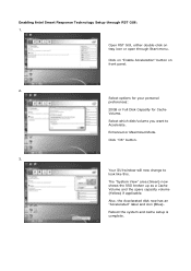
... the Cache device, which HDD you wish to Accelerate, if you want to use the full SSD as Cache device or only 20GB, and if you just need to set the UEFI option "... 6. For the new version RST driver, please check our website for the latest information: http://www.asrock.com * Before you use RST function, you want to [RAID Mode]. UI setup instruction: 1. It is not necessary... to accelerate AND the SSD in RAID ROM. You MUST have both the HDD you intend to build RAID 0 or RAID 1 in system...
... the Cache device, which HDD you wish to Accelerate, if you want to use the full SSD as Cache device or only 20GB, and if you just need to set the UEFI option "... 6. For the new version RST driver, please check our website for the latest information: http://www.asrock.com * Before you use RST function, you want to [RAID Mode]. UI setup instruction: 1. It is not necessary... to accelerate AND the SSD in RAID ROM. You MUST have both the HDD you intend to build RAID 0 or RAID 1 in system...
Intel Smart Response Installation Guide
Page 2
... Disk Capacity for Cache Volume. Enhanced or Maximized Mode. Your GUI window will now change to Accelerate. The "System View" area (Green) now shows the SSD broken up as a Cache Volume and the spare capacity volume (Yellow) if applicable. Also, the Accelerated disk now has an "Accelerated" label and icon (Blue...
... Disk Capacity for Cache Volume. Enhanced or Maximized Mode. Your GUI window will now change to Accelerate. The "System View" area (Green) now shows the SSD broken up as a Cache Volume and the spare capacity volume (Yellow) if applicable. Also, the Accelerated disk now has an "Accelerated" label and icon (Blue...
Intel Smart Response Installation Guide
Page 4
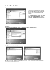
Note that the SSD is now reset to Available. The "Accelerate" tab window will delete all data on the Spare Capacity Volume! WARNING! Resetting SSD to "Available". Resetting SSD to "Available": 1. The SSD can now be used as a normal storage device, or you can also re-enable Acceleration through the normal enable process. The SSD is still divided into a Cache and Spare Cap Volume. To reset SSD to a non-Cache-disk state, Click the "Reset to Available will now look like this. Resetting SSD to Available" button (Orange).
Note that the SSD is now reset to Available. The "Accelerate" tab window will delete all data on the Spare Capacity Volume! WARNING! Resetting SSD to "Available". Resetting SSD to "Available": 1. The SSD can now be used as a normal storage device, or you can also re-enable Acceleration through the normal enable process. The SSD is still divided into a Cache and Spare Cap Volume. To reset SSD to a non-Cache-disk state, Click the "Reset to Available will now look like this. Resetting SSD to Available" button (Orange).

User Manual
Page 43
... 3.0 Panel with six chassis screws. 43 The Installation Guide of Front USB 3.0 Panel Step 1 Prepare the bundled Front USB 3.0 Panel, four Step 2 Screw the 2.5" HDD/SSD to this motherboard. Step 3 Intall the Front USB 3.0 Panel into the 2.5" drive bay of HDMI VGA card to the Front HDD screws, and six chassis...
... 3.0 Panel with six chassis screws. 43 The Installation Guide of Front USB 3.0 Panel Step 1 Prepare the bundled Front USB 3.0 Panel, four Step 2 Screw the 2.5" HDD/SSD to this motherboard. Step 3 Intall the Front USB 3.0 Panel into the 2.5" drive bay of HDMI VGA card to the Front HDD screws, and six chassis...

Quick Installation Guide
Page 38
English 38 ASRock Z68 Extreme4 Gen3 Motherboard This COM1 header supports a serial port module. This IEEE 1394 header can support one IEEE 1394 header (FRONT_1394) on the I/O panel, there is one ... 3 Intall the Front USB 3.0 Panel into the 2.5" drive bay of Front USB 3.0 Panel Step 1 Prepare the bundled Front USB 3.0 Panel, four Step 2 Screw the 2.5" HDD/SSD to the drive bay with four HDD screws. IEEE 1394 Header (9-pin FRONT_1394) (see p.2 No. 32) Serial port Header (9-pin COM1) (see p.2 No. 37) 1 GND...
English 38 ASRock Z68 Extreme4 Gen3 Motherboard This COM1 header supports a serial port module. This IEEE 1394 header can support one IEEE 1394 header (FRONT_1394) on the I/O panel, there is one ... 3 Intall the Front USB 3.0 Panel into the 2.5" drive bay of Front USB 3.0 Panel Step 1 Prepare the bundled Front USB 3.0 Panel, four Step 2 Screw the 2.5" HDD/SSD to the drive bay with four HDD screws. IEEE 1394 Header (9-pin FRONT_1394) (see p.2 No. 32) Serial port Header (9-pin COM1) (see p.2 No. 37) 1 GND...

Quick Installation Guide
Page 240
전면 USB 3.0 1 USB 3.0 2 HDD 2.5" HDD/SSD USB 3.0 3 USB 3.0 2.5 4 USB 3.0 5 USB 3.0 USB 3.0 헤더(USB3_12_13 6 USB 3.0 한 국 어 후면 USB 3.0 1 USB 3.0 2 단계 USB 3.0 USB 3.0 3 USB 3.0 4 USB 3.0 240 ASRock Z68 Extreme4 Gen3 Motherboard
전면 USB 3.0 1 USB 3.0 2 HDD 2.5" HDD/SSD USB 3.0 3 USB 3.0 2.5 4 USB 3.0 5 USB 3.0 USB 3.0 헤더(USB3_12_13 6 USB 3.0 한 국 어 후면 USB 3.0 1 USB 3.0 2 단계 USB 3.0 USB 3.0 3 USB 3.0 4 USB 3.0 240 ASRock Z68 Extreme4 Gen3 Motherboard

Quick Installation Guide
Page 291
... 3.0 HDD HDMI_SPDIF SPDIF HDMI HDMI HDMI 顯卡的 HDMI_SPDIF 步驟 2 用四個 HDD 螺絲將 2.5"HDD/SSD USB 3.0 步驟 3 將前部USB 3.0 2.5 步驟 4 USB 3.0 步驟 5 將前部USB 3.0 USB 3.0接頭 (USB3_12_13)。 步驟 6 USB 3.0 簡體中文 291 ASRock Z68 Extreme4 Gen3 Motherboard
... 3.0 HDD HDMI_SPDIF SPDIF HDMI HDMI HDMI 顯卡的 HDMI_SPDIF 步驟 2 用四個 HDD 螺絲將 2.5"HDD/SSD USB 3.0 步驟 3 將前部USB 3.0 2.5 步驟 4 USB 3.0 步驟 5 將前部USB 3.0 USB 3.0接頭 (USB3_12_13)。 步驟 6 USB 3.0 簡體中文 291 ASRock Z68 Extreme4 Gen3 Motherboard
