User Manual
Page 8
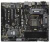
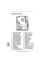
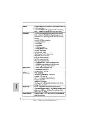
...with LED - 1 x Power Switch with LED - 1 x Reset Switch with GUI support - ASRock MAGIX Multimedia Suite - Supports jumperfree - SMBIOS 2.3.1 Support - AMI UEFI Legal BIOS with LED - 64Mb AMI BIOS - ASRock Extreme Tuning Utility (AXTU) (see CAUTION 9) - USB3.0 Connector Smart Switch BIOS Feature Support CD Unique Feature - 2 x Rear USB 3.0 ports ... 12V power connector - Supports "Plug and Play" - Drivers, Utilities, AntiVirus Software (Trial Version), CyberLink MediaEspresso 6.5 Trial, ASRock Software Suite (CyberLink DVD Suite - OEM) - SLI/XFire power connector -
...with LED - 1 x Power Switch with LED - 1 x Reset Switch with GUI support - ASRock MAGIX Multimedia Suite - Supports jumperfree - SMBIOS 2.3.1 Support - AMI UEFI Legal BIOS with LED - 64Mb AMI BIOS - ASRock Extreme Tuning Utility (AXTU) (see CAUTION 9) - USB3.0 Connector Smart Switch BIOS Feature Support CD Unique Feature - 2 x Rear USB 3.0 ports ... 12V power connector - Supports "Plug and Play" - Drivers, Utilities, AntiVirus Software (Trial Version), CyberLink MediaEspresso 6.5 Trial, ASRock Software Suite (CyberLink DVD Suite - OEM) - SLI/XFire power connector -

User Manual
Page 13
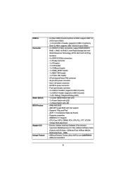
...PCIE2 RoHS PCIE3 PCI Express 3.0 PCI1 Z68 Extreme4 Gen3 CMOS Battery PCIE4 XFast USB PCI2 DX10.1 Front USB 3.0 1394a FLOPPY1 PCIE5 IR1 1 FRONT_1394 1 USB6_7 1 1 CIR1 USB8_9 1 Intel Z68 SATA2_4_5 64Mb BIOS RSTBTN Dr. Debug USB10_11 1 USB3_12_13 PWRBTN PLED1 1 SPEAKER1 1 PANEL1 PLED PWRBTN 1 HDLED RESET SATA2_2_3 8 9 10 11 12 ...41 PCI Slot (PCI1) 19 64Mb SPI Flash 42 PCI Express 2.0 x1 Slot (PCIE3, Black) 20 Intel Z68 Chipset 43 PCI Express 3.0 x16 Slot (PCIE2, Black) 21 Reset Switch (RSTBTN) 44 PCI Express 2.0 x1 Slot (PCIE1, Black) 22 Power Switch (PWRBTN) 45 SLI /...
...PCIE2 RoHS PCIE3 PCI Express 3.0 PCI1 Z68 Extreme4 Gen3 CMOS Battery PCIE4 XFast USB PCI2 DX10.1 Front USB 3.0 1394a FLOPPY1 PCIE5 IR1 1 FRONT_1394 1 USB6_7 1 1 CIR1 USB8_9 1 Intel Z68 SATA2_4_5 64Mb BIOS RSTBTN Dr. Debug USB10_11 1 USB3_12_13 PWRBTN PLED1 1 SPEAKER1 1 PANEL1 PLED PWRBTN 1 HDLED RESET SATA2_2_3 8 9 10 11 12 ...41 PCI Slot (PCI1) 19 64Mb SPI Flash 42 PCI Express 2.0 x1 Slot (PCIE3, Black) 20 Intel Z68 Chipset 43 PCI Express 3.0 x16 Slot (PCIE2, Black) 21 Reset Switch (RSTBTN) 44 PCI Express 2.0 x1 Slot (PCIE1, Black) 22 Power Switch (PWRBTN) 45 SLI /...

User Manual
Page 37
... the data in CMOS. The Clear CMOS Switch has the same function as the Clear CMOS jumper. 37 To clear and reset the system parameters to clear the CMOS when you just nish updating the BIOS, you must boot up the system rst, and then shut it down before you update the... BIOS. 2.11 Jumpers Setup The illustration shows how jumpers are "Short" when jumper cap is placed on these 2 pins. When the jumper cap...
... the data in CMOS. The Clear CMOS Switch has the same function as the Clear CMOS jumper. 37 To clear and reset the system parameters to clear the CMOS when you just nish updating the BIOS, you must boot up the system rst, and then shut it down before you update the... BIOS. 2.11 Jumpers Setup The illustration shows how jumpers are "Short" when jumper cap is placed on these 2 pins. When the jumper cap...
Quick Installation Guide
Page 2
... (PCIE2, Black) 21 Reset Switch (RSTBTN) 44 PCI Express 2.0 x1 Slot (PCIE1, Black) 22 Power Switch (PWRBTN) 45 SLI / XFIRE Power Connector 23 Power LED Header (PLED1) 46 Chassis Fan Connector (CHA_FAN3) 24 System Panel Header (PANEL1, Black) 47 Chassis Fan Connector (CHA_FAN2) 25 Chassis Speaker Header (SPEAKER 1, Black) 2 ASRock Z68 Extreme4 Gen3 Motherboard English
... (PCIE2, Black) 21 Reset Switch (RSTBTN) 44 PCI Express 2.0 x1 Slot (PCIE1, Black) 22 Power Switch (PWRBTN) 45 SLI / XFIRE Power Connector 23 Power LED Header (PLED1) 46 Chassis Fan Connector (CHA_FAN3) 24 System Panel Header (PANEL1, Black) 47 Chassis Fan Connector (CHA_FAN2) 25 Chassis Speaker Header (SPEAKER 1, Black) 2 ASRock Z68 Extreme4 Gen3 Motherboard English
Quick Installation Guide
Page 8
... with LED - 1 x Power Switch with LED - 1 x Reset Switch with GUI support - Supports "Plug and Play" - OEM) - AMI UEFI Legal BIOS with LED - 64Mb AMI BIOS - CPU Core, IGPU, DRAM, PCH, CPU PLL, VTT, VCCSA Voltage Multi-adjustment - ASRock Extreme Tuning Utility (AXTU) (see CAUTION 9) - ASRock Instant Boot English 8 ASRock Z68 Extreme4 Gen3 Motherboard Supports jumperfree - CPU/Chassis/Power FAN...
... with LED - 1 x Power Switch with LED - 1 x Reset Switch with GUI support - Supports "Plug and Play" - OEM) - AMI UEFI Legal BIOS with LED - 64Mb AMI BIOS - CPU Core, IGPU, DRAM, PCH, CPU PLL, VTT, VCCSA Voltage Multi-adjustment - ASRock Extreme Tuning Utility (AXTU) (see CAUTION 9) - ASRock Instant Boot English 8 ASRock Z68 Extreme4 Gen3 Motherboard Supports jumperfree - CPU/Chassis/Power FAN...

Quick Installation Guide
Page 32
... Jumper (CLRCMOS1) (see p.2, No. 10) Setting Default Clear CMOS Description Note: CLRCMOS1 allows you do not clear the CMOS right after you update the BIOS. English 32 ASRock Z68 Extreme4 Gen3 Motherboard However, please do the clear-CMOS action. Please be noted that the password, date, time, user default profile, 1394 GUID and... 15 seconds, use a jumper cap to default setup, please turn off the computer and unplug the power cord from the power supply. To clear and reset the system parameters to short pin2 and pin3 on pins, the jumper is "Short".
... Jumper (CLRCMOS1) (see p.2, No. 10) Setting Default Clear CMOS Description Note: CLRCMOS1 allows you do not clear the CMOS right after you update the BIOS. English 32 ASRock Z68 Extreme4 Gen3 Motherboard However, please do the clear-CMOS action. Please be noted that the password, date, time, user default profile, 1394 GUID and... 15 seconds, use a jumper cap to default setup, please turn off the computer and unplug the power cord from the power supply. To clear and reset the system parameters to short pin2 and pin3 on pins, the jumper is "Short".

Quick Installation Guide
Page 47
... after POST, please restart the system by pressing + + , or pressing the reset button on the system chassis. It will enhance motherboard features. The BIOS Setup program is a menu-driven program, which allows you wish to display the menus. 47 ASRock Z68 Extreme4 Gen3 Motherboard English Software Support CD information This motherboard supports various Microsoft® Windows...
... after POST, please restart the system by pressing + + , or pressing the reset button on the system chassis. It will enhance motherboard features. The BIOS Setup program is a menu-driven program, which allows you wish to display the menus. 47 ASRock Z68 Extreme4 Gen3 Motherboard English Software Support CD information This motherboard supports various Microsoft® Windows...


