
Intel Rapid Storage Guide
Page 12
... use the up or down arrow keys to select the RAID level and press Enter. 4. Switch the SATA Operation Mode option to enter the BIOS Setup program after the Power-On-Self-Test (POST) memory test begins. 2. Use the up or down arrow keys to scroll through the...the option ROM user interface. 2. Click F10 to create a RAID volume. 1. Create a RAID Volume Use the following steps to save the BIOS settings and exit the BIOS Setup program. Press Enter to select the physical disks. 6. The F6 installation method is not required for Microsoft Windows 7 or Note Microsoft Windows ...
... use the up or down arrow keys to select the RAID level and press Enter. 4. Switch the SATA Operation Mode option to enter the BIOS Setup program after the Power-On-Self-Test (POST) memory test begins. 2. Use the up or down arrow keys to scroll through the...the option ROM user interface. 2. Click F10 to create a RAID volume. 1. Create a RAID Volume Use the following steps to save the BIOS settings and exit the BIOS Setup program. Press Enter to select the physical disks. 6. The F6 installation method is not required for Microsoft Windows 7 or Note Microsoft Windows ...
RAID Installation Guide
Page 1
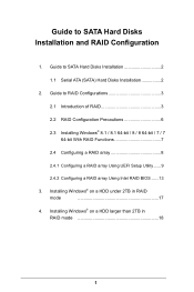
...; 8.1 / 8.1 64-bit / 8 / 8 64-bit / 7 / 7 64-bit With RAID Functions 7 2.4 Configuring a RAID array 8 2.4.1 Configuring a RAID array Using UEFI Setup Utility....... 9 2.4.2 Configuring a RAID array Using Intel RAID BIOS....... 13 3.
...; 8.1 / 8.1 64-bit / 8 / 8 64-bit / 7 / 7 64-bit With RAID Functions 7 2.4 Configuring a RAID array 8 2.4.1 Configuring a RAID array Using UEFI Setup Utility....... 9 2.4.2 Configuring a RAID array Using Intel RAID BIOS....... 13 3.
RAID Installation Guide
Page 7
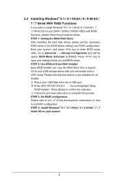
...BIOS RAID Items After installing the hard disk drives, please set the necessary RAID items in UEFI setup. STEP 4: Install Windows® 8.1 / 8.1 64-bit / 8 / 8 64-bit / 7 / 7 64-bit OS on your USB flash drive into a USB port B. Enter UEFI SETUP UTILITY Tool and highlight "Easy RAID Installer". STEP 2: Use ASRock...2.3 Installing Windows® 8.1 / 8.1 64-bit / 8 / 8 64-bit / 7 / 7 64-bit With RAID Functions If you exit BIOS setup. Press [Enter] to complete the process. STEP 3: Set RAID configuration Please refer to [RAID]. Go to install Windows® 8.1 / 8.1 ...
...BIOS RAID Items After installing the hard disk drives, please set the necessary RAID items in UEFI setup. STEP 4: Install Windows® 8.1 / 8.1 64-bit / 8 / 8 64-bit / 7 / 7 64-bit OS on your USB flash drive into a USB port B. Enter UEFI SETUP UTILITY Tool and highlight "Easy RAID Installer". STEP 2: Use ASRock...2.3 Installing Windows® 8.1 / 8.1 64-bit / 8 / 8 64-bit / 7 / 7 64-bit With RAID Functions If you exit BIOS setup. Press [Enter] to complete the process. STEP 3: Set RAID configuration Please refer to [RAID]. Go to install Windows® 8.1 / 8.1 ...
RAID Installation Guide
Page 8
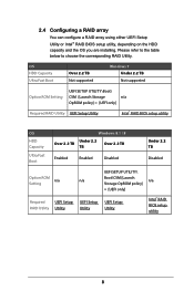
...Setting UEFI SETUP UTILITY\Boot\ CSM [Launch Storage n/a OpROM policy] = [UEFI only] Required RAID Utility UEFI Setup Utility Intel® RAID BIOS setup utility OS HDD Capacity Ultra Fast Boot Windows 8.1 / 8 Under 2.2 Over 2.2 TB TB Over 2.2 TB Enabled Enabled Disabled Under 2.2 ...n/a Setting Storage OpROM policy] = [UEFI only] Required UEFI Setup UEFI Setup UEFI Setup RAID Utility Utility Utility Utility Intel® RAID BIOS setup utility 8 Please refer to the table below to choose the corresponding RAID Utility. 2.4 Configuring a RAID array You can configure a RAID...
...Setting UEFI SETUP UTILITY\Boot\ CSM [Launch Storage n/a OpROM policy] = [UEFI only] Required RAID Utility UEFI Setup Utility Intel® RAID BIOS setup utility OS HDD Capacity Ultra Fast Boot Windows 8.1 / 8 Under 2.2 Over 2.2 TB TB Over 2.2 TB Enabled Enabled Disabled Under 2.2 ...n/a Setting Storage OpROM policy] = [UEFI only] Required UEFI Setup UEFI Setup UEFI Setup RAID Utility Utility Utility Utility Intel® RAID BIOS setup utility 8 Please refer to the table below to choose the corresponding RAID Utility. 2.4 Configuring a RAID array You can configure a RAID...
RAID Installation Guide
Page 13
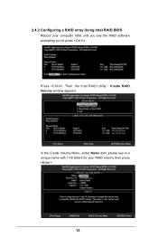
Wait until you see the RAID software prompting you to press . Create RAID Volume window appears. 2.4.2 Configuring a RAID array Using Intel RAID BIOS Reboot your RAID volume then press . Press . In the Create Volume Menu, under Name item, please key-in a unique name with 1-16 letters for your computer. Volume0 13 Then, the Intel RAID Utility -
Wait until you see the RAID software prompting you to press . Create RAID Volume window appears. 2.4.2 Configuring a RAID array Using Intel RAID BIOS Reboot your RAID volume then press . Press . In the Create Volume Menu, under Name item, please key-in a unique name with 1-16 letters for your computer. Volume0 13 Then, the Intel RAID Utility -
RAID Installation Guide
Page 16
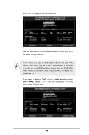
If you set up. After the completion, you will see the detailed information about the RAID that you install OS. If you want to delete a RAID volume, please select the option Delete RAID Volume, press , and then follow the instructions on the screen. 16 Press to create one RAID partition at a time under BIOS RAID environment. Please note that you want to create an extra RAID partition, please use the RAID utility under Windows environment to configure RAID functions after you are only allowed to complete the setup of RAID.
If you set up. After the completion, you will see the detailed information about the RAID that you install OS. If you want to delete a RAID volume, please select the option Delete RAID Volume, press , and then follow the instructions on the screen. 16 Press to create one RAID partition at a time under BIOS RAID environment. Please note that you want to create an extra RAID partition, please use the RAID utility under Windows environment to configure RAID functions after you are only allowed to complete the setup of RAID.
RAID Installation Guide
Page 17
3. Installing Windows® on a HDD under 2TB in RAID mode After the UEFI and RAID BIOS setup you may start installing Windows® 8.1 / 8.1 64-bit / 8 / 8 64-bit / 7 / 7 64-bit OS as usual. 17
3. Installing Windows® on a HDD under 2TB in RAID mode After the UEFI and RAID BIOS setup you may start installing Windows® 8.1 / 8.1 64-bit / 8 / 8 64-bit / 7 / 7 64-bit OS as usual. 17
RAID Installation Guide
Page 18
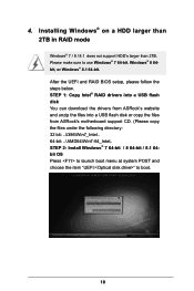
STEP 1: Copy Intel® RAID drivers into a USB flash disk You can download the drivers from ASRock's website and unzip the files into a USB flash disk or copy the files from ASRock's motherboard support CD. (Please copy the files under the following directory: 32 bit: ..\i386\Win7_Intel.. 64-bit: ..\AMD64\Win7-64_Intel.. Installing...:" to use Windows® 7 64-bit, Windows® 8 64bit, or Windows® 8.1 64-bit. Please make sure to boot. 18 4. After the UEFI and RAID BIOS setup, please follow the steps below.
STEP 1: Copy Intel® RAID drivers into a USB flash disk You can download the drivers from ASRock's website and unzip the files into a USB flash disk or copy the files from ASRock's motherboard support CD. (Please copy the files under the following directory: 32 bit: ..\i386\Win7_Intel.. 64-bit: ..\AMD64\Win7-64_Intel.. Installing...:" to use Windows® 7 64-bit, Windows® 8 64bit, or Windows® 8.1 64-bit. Please make sure to boot. 18 4. After the UEFI and RAID BIOS setup, please follow the steps below.
User Manual
Page 5
... 2.13 HDD Saver Cable Installation Guide 48 Chapter 3 Software and Utilities Operation 49 3.1 Installing Drivers 49 3.2 Formula Drive 50 3.3 ASRock Cloud (on Qualcomm® Atheros® AR8171) 56 3.4 ASRock APP Shop 66 3.4.1 UI Overview 66 3.4.2 Apps 67 3.4.3 BIOS & Drivers 70 3.4.4 Setting 71 3.5 Start8 72 Chapter 4 UEFI SETUP UTILITY 78 4.1 Introduction 78 4.1.1 UEFI Menu Bar...
... 2.13 HDD Saver Cable Installation Guide 48 Chapter 3 Software and Utilities Operation 49 3.1 Installing Drivers 49 3.2 Formula Drive 50 3.3 ASRock Cloud (on Qualcomm® Atheros® AR8171) 56 3.4 ASRock APP Shop 66 3.4.1 UI Overview 66 3.4.2 Apps 67 3.4.3 BIOS & Drivers 70 3.4.4 Setting 71 3.5 Start8 72 Chapter 4 UEFI SETUP UTILITY 78 4.1 Introduction 78 4.1.1 UEFI Menu Bar...

User Manual
Page 7
.... Because the motherboard speciications and the BIOS sotware might be available on ASRock's website as well. You may ind the latest VGA cards and CPU support list on ASRock's website without notice. ASRock website http://www.asrock.com. 1.1 Package Contents • ASRock X99 OC Formula Motherboard (EATX Form Factor) • ASRock X99 OC Formula Quick Installation Guide • ASRock X99 OC Formula Support CD • 1 x I/O Panel Shield...
.... Because the motherboard speciications and the BIOS sotware might be available on ASRock's website as well. You may ind the latest VGA cards and CPU support list on ASRock's website without notice. ASRock website http://www.asrock.com. 1.1 Package Contents • ASRock X99 OC Formula Motherboard (EATX Form Factor) • ASRock X99 OC Formula Quick Installation Guide • ASRock X99 OC Formula Support CD • 1 x I/O Panel Shield...

User Manual
Page 11
... LED • V-ProbeTM: 7-set of onboard voltage measurement points laid • Rapid OC Buttons: +/- X99 OC Formula BIOS Feature Hardware Monitor OS Certiications • 1 x Vertical Type A USB 3.0 • 2 x USB 3.0 Headers (Support 4 USB 3.0 ports) (ASMedia ASM1074 hub) (Supports ESD Protection (ASRock Full Spike Protection)) • 1 x Dr. Debug with LED • 1 x Power Switch with LED • 1 x Reset Switch...
... LED • V-ProbeTM: 7-set of onboard voltage measurement points laid • Rapid OC Buttons: +/- X99 OC Formula BIOS Feature Hardware Monitor OS Certiications • 1 x Vertical Type A USB 3.0 • 2 x USB 3.0 Headers (Support 4 USB 3.0 ports) (ASMedia ASM1074 hub) (Supports ESD Protection (ASRock Full Spike Protection)) • 1 x Dr. Debug with LED • 1 x Power Switch with LED • 1 x Reset Switch...

User Manual
Page 12
...devices of your own risk and expense. * For detailed product information, please visit our website: http://www.asrock.com Please realize that Windows® cannot use ASRock XFast RAM to utilize the memory that there is a certain risk involved with overclocking, including adjusting the setting... in the BIOS, applying Untied Overclocking Technology, or using third-party overclocking tools. It should be less than ...
...devices of your own risk and expense. * For detailed product information, please visit our website: http://www.asrock.com Please realize that Windows® cannot use ASRock XFast RAM to utilize the memory that there is a certain risk involved with overclocking, including adjusting the setting... in the BIOS, applying Untied Overclocking Technology, or using third-party overclocking tools. It should be less than ...

User Manual
Page 13
X99 OC Formula 1.3 Motherboard Layout 12 3 4 5 67 8 USB 2.0 T: USB1 B: USB2 PS2 Keyboard /Mouse DDR4_D2 (64 bit, 284-pin module) DDR4_D1 (64 bit, 284-pin module) DDR4_C2 (... 23 MINI_PCIE1 Purity SoundTM 2 CT5 HD_AUDIO1 1 T BT1 1 SATA3_0_1 PCIE2 PCIE3 X99 OC Formula PCIE4 Intel X99 SATA3_2_3 SATA3_4_5 Ultra M.2 PCIe Gen3 x4 ULTRA_M2 CT4 PCIE_PWR1 CT3 CT2 Super I/O PCIE5 COM1 1 CHA_FAN1 USB5_6 USB3_4 CLRMOS1 1 1 1 1 Super I/O TPMS1 BIOS_A 128Mb BIOS BIOS_A 128Mb BIOS BIOS_A_LED BIOS_A_LED CHA_FAN2 Reset Power 1 PLED1 1 SPEAKER1 PLED PWRBTN 1 HDLED RESET ...
X99 OC Formula 1.3 Motherboard Layout 12 3 4 5 67 8 USB 2.0 T: USB1 B: USB2 PS2 Keyboard /Mouse DDR4_D2 (64 bit, 284-pin module) DDR4_D1 (64 bit, 284-pin module) DDR4_C2 (... 23 MINI_PCIE1 Purity SoundTM 2 CT5 HD_AUDIO1 1 T BT1 1 SATA3_0_1 PCIE2 PCIE3 X99 OC Formula PCIE4 Intel X99 SATA3_2_3 SATA3_4_5 Ultra M.2 PCIe Gen3 x4 ULTRA_M2 CT4 PCIE_PWR1 CT3 CT2 Super I/O PCIE5 COM1 1 CHA_FAN1 USB5_6 USB3_4 CLRMOS1 1 1 1 1 Super I/O TPMS1 BIOS_A 128Mb BIOS BIOS_A 128Mb BIOS BIOS_A_LED BIOS_A_LED CHA_FAN2 Reset Power 1 PLED1 1 SPEAKER1 PLED PWRBTN 1 HDLED RESET ...

User Manual
Page 14
...284-pin DDR4 DIMM Slots (DDR4_D2, DDR4_C2) 7 2 x 284-pin DDR4 DIMM Slots (DDR4_D1, DDR4_C1) 8 CPU Fan Connector (CPU_FAN2) 9 Rapid OC Button (+) (PLUS) 10 Rapid OC Button (-) (MINUS) 11 Menu Button (MENU) 12 PCIe ON/OFF Switch (SWITCH1) 13 LN2 Mode Switch (LN2MODE) 14 Slow Mode Switch (SLOWMODE...Connectors (S_SATA3_2_3) 24 SATA3 Connectors (SATA3_0_1) 25 SATA3 Connectors (SATA3_2_3) 26 SATA3 Connectors (SATA3_4_5) 27 HDD Saver Connector (SATA_PWR_1) 28 BIOS Selection Switch (BIOS_SEL1) 29 Power LED Header (PLED1) 30 Direct Key Button (DIRKEY1) 31 Chassis Speaker Header (SPEAKER1) 32 System Panel...
...284-pin DDR4 DIMM Slots (DDR4_D2, DDR4_C2) 7 2 x 284-pin DDR4 DIMM Slots (DDR4_D1, DDR4_C1) 8 CPU Fan Connector (CPU_FAN2) 9 Rapid OC Button (+) (PLUS) 10 Rapid OC Button (-) (MINUS) 11 Menu Button (MENU) 12 PCIe ON/OFF Switch (SWITCH1) 13 LN2 Mode Switch (LN2MODE) 14 Slow Mode Switch (SLOWMODE...Connectors (S_SATA3_2_3) 24 SATA3 Connectors (SATA3_0_1) 25 SATA3 Connectors (SATA3_2_3) 26 SATA3 Connectors (SATA3_4_5) 27 HDD Saver Connector (SATA_PWR_1) 28 BIOS Selection Switch (BIOS_SEL1) 29 Power LED Header (PLED1) 30 Direct Key Button (DIRKEY1) 31 Chassis Speaker Header (SPEAKER1) 32 System Panel...

User Manual
Page 27
... Jumper (CLRCMOS1) (see p.7, No. 40) Default Clear CMOS CLRCMOS1 allows you update the BIOS. To clear and reset the system parameters to short pin2 and pin3 on CLRCMOS1 for 5 ...power cord from the power supply. If you need to clear the CMOS when you just inish updating the BIOS, you must boot up the system irst, and then shut it down before you do not clear the CMOS...cleared only if the CMOS battery is removed. However, please do the clear-CMOS action. X99 OC Formula 2.5 Jumpers Setup he illustration shows how jumpers are "Short" when a jumper cap is placed on these 2 pins.
... Jumper (CLRCMOS1) (see p.7, No. 40) Default Clear CMOS CLRCMOS1 allows you update the BIOS. To clear and reset the system parameters to short pin2 and pin3 on CLRCMOS1 for 5 ...power cord from the power supply. If you need to clear the CMOS when you just inish updating the BIOS, you must boot up the system irst, and then shut it down before you do not clear the CMOS...cleared only if the CMOS battery is removed. However, please do the clear-CMOS action. X99 OC Formula 2.5 Jumpers Setup he illustration shows how jumpers are "Short" when a jumper cap is placed on these 2 pins.

User Manual
Page 34
... system stability, or even cause damage to quickly clear the CMOS values. his function is workable only when you power of the system. English Rapid OC Buttons + (MINUS: see p.7, No. 10) (PLUS: see p.10, No. 13) Clear CMOS Switch allows users to the components and devices. Overclocking may...among Date/ Time, Temperature, and Voltage information. 2.7 Smart Switches he motherboard has eleven smart switches: Power Switch, Reset Switch, Clear CMOS Switch, Rapid OC Buttons, Menu Button, PCIe ON/OFF Switch, Slow Mode Switch, BIOS Selection Switch, LN2 Mode Switch and Direct Key Button.
... system stability, or even cause damage to quickly clear the CMOS values. his function is workable only when you power of the system. English Rapid OC Buttons + (MINUS: see p.7, No. 10) (PLUS: see p.10, No. 13) Clear CMOS Switch allows users to the components and devices. Overclocking may...among Date/ Time, Temperature, and Voltage information. 2.7 Smart Switches he motherboard has eleven smart switches: Power Switch, Reset Switch, Clear CMOS Switch, Rapid OC Buttons, Menu Button, PCIe ON/OFF Switch, Slow Mode Switch, BIOS Selection Switch, LN2 Mode Switch and Direct Key Button.

User Manual
Page 35
... motherboard has two BIOS chips, a primary BIOS (BIOS_A) and a backup BIOS (BIOS_ B), which BIOS is for debug only. BIOS Selection Switch (BIOS_SEL1) (see p.7, No. 28) AB BIOS Selection Switch allows the system to update the backup BIOS manually. Make sure that , use your PCIE card could be burnt if it from either BIOS A or BIOS B. X99 OC Formula 1234 OFF PCIe ON...
... motherboard has two BIOS chips, a primary BIOS (BIOS_A) and a backup BIOS (BIOS_ B), which BIOS is for debug only. BIOS Selection Switch (BIOS_SEL1) (see p.7, No. 28) AB BIOS Selection Switch allows the system to update the backup BIOS manually. Make sure that , use your PCIE card could be burnt if it from either BIOS A or BIOS B. X99 OC Formula 1234 OFF PCIe ON...
User Manual
Page 60
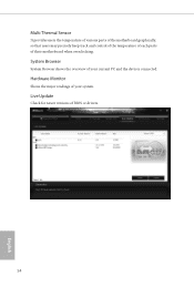
System Browser System Browser shows the overview of your current PC and the devices connected. Multi Thermal Sensor It provides users the temperature of various parts of the motherboard graphically, so that users may precisely keep track and control of the temperature of each parts of BIOS or drivers. 54 English Hardware Monitor Shows the major readings of your system. Live Update Check for newer versions of their motherboard when overclocking.
System Browser System Browser shows the overview of your current PC and the devices connected. Multi Thermal Sensor It provides users the temperature of various parts of the motherboard graphically, so that users may precisely keep track and control of the temperature of each parts of BIOS or drivers. 54 English Hardware Monitor Shows the major readings of your system. Live Update Check for newer versions of their motherboard when overclocking.

User Manual
Page 76
Click to select one or more details. Step 3 Click Update to update. Click on Step 2 to see a list of recommended or critical updates for the BIOS or drivers. Please update them all soon. Step 1 Please check the item information before update. 3.4.3 BIOS & Drivers Installing BIOS or Drivers When the "BIOS & Drivers" tab is selected, you will see more items you want to start the update process. 70 English
Click to select one or more details. Step 3 Click Update to update. Click on Step 2 to see a list of recommended or critical updates for the BIOS or drivers. Please update them all soon. Step 1 Please check the item information before update. 3.4.3 BIOS & Drivers Installing BIOS or Drivers When the "BIOS & Drivers" tab is selected, you will see more items you want to start the update process. 70 English

User Manual
Page 105
... Support Enable or disable Legacy OS Support for USB 3.0 devices. If you encounter USB compatibility issues it is enabled in BIOS). Select UEFI Setup Only to disable legacy USB support. 4.4.6 USB Coniguration X99 OC Formula USB Controller Enable or disable all the USB ports. Set [Auto] to automatically enable the USB 3.0 driver ater entering... (USB 3.0 is recommended to disable the USB 3.0 ports. Set [Disabled] to disable legacy USB support. If you encounter USB compatibility issues it is disabled in BIOS).
... Support Enable or disable Legacy OS Support for USB 3.0 devices. If you encounter USB compatibility issues it is enabled in BIOS). Select UEFI Setup Only to disable legacy USB support. 4.4.6 USB Coniguration X99 OC Formula USB Controller Enable or disable all the USB ports. Set [Auto] to automatically enable the USB 3.0 driver ater entering... (USB 3.0 is recommended to disable the USB 3.0 ports. Set [Disabled] to disable legacy USB support. If you encounter USB compatibility issues it is disabled in BIOS).


