
User Manual
Page 6
ATX Form Factor: 12.0-in x 9.6-in Socket LGA 2011 - Intel® X79 - Quad Channel DDR3 Memory Technology (see CAUTION 3) - Max. Supports AMDTM Quad CrossFireXTM, 3-Way CrossFireXTM and CrossFireXTM - PCIE x1 Gigabit LAN 10/100/... - Supports NVIDIA® Quad SLITM, 3-Way SLITM and SLITM - 7.1 CH HD Audio with Intel® Workstation 1S Xeon® processors E5 2xxx & 4xxx series in socket LGA 2011 - quality Conductive Polymer Capacitors) - Supports Hyper-Threading Technology (see CAUTION 4) - 2 x PCI Express 2.0 x 1 slots - 2 x PCI slots - Supports Intel® CoreTM ...
ATX Form Factor: 12.0-in x 9.6-in Socket LGA 2011 - Intel® X79 - Quad Channel DDR3 Memory Technology (see CAUTION 3) - Max. Supports AMDTM Quad CrossFireXTM, 3-Way CrossFireXTM and CrossFireXTM - PCIE x1 Gigabit LAN 10/100/... - Supports NVIDIA® Quad SLITM, 3-Way SLITM and SLITM - 7.1 CH HD Audio with Intel® Workstation 1S Xeon® processors E5 2xxx & 4xxx series in socket LGA 2011 - quality Conductive Polymer Capacitors) - Supports Hyper-Threading Technology (see CAUTION 4) - 2 x PCI Express 2.0 x 1 slots - 2 x PCI slots - Supports Intel® CoreTM ...

User Manual
Page 9
... Overclocking Technology, or using third-party overclocking tools. In Hardware Monitor, it with 64-bit CPU, there is already PCIE 3.0 hardware ready. ASRock website: http://www.asrock.com 7. Currently Intel® Socket 2011 Sandy Bridge-E Processor doesn't support PCIE 3.0, but this utility, you to enable PCIE 3.0. Please visit our website for proper installation...
... Overclocking Technology, or using third-party overclocking tools. In Hardware Monitor, it with 64-bit CPU, there is already PCIE 3.0 hardware ready. ASRock website: http://www.asrock.com 7. Currently Intel® Socket 2011 Sandy Bridge-E Processor doesn't support PCIE 3.0, but this utility, you to enable PCIE 3.0. Please visit our website for proper installation...
User Manual
Page 12
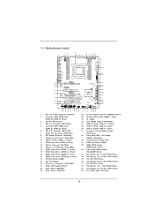
... PCIE1 42 PCIE2 CHA_FAN2 11 SATA3 6Gb/s 12 13 SATA2_2_3 XFast LAN SB_FAN1 14 41 PCI1 SATA2_0_1 Intel 15 40 PCIE3 X79 SATA3_0_1 Super 16 I/O X79 Extreme4 CMOS 39 PCI2 Battery 64Mb BIOS 17 SATA3_A0_A1 2 oz Copper PCB XFast USB 18 38 37 PCIE4 AUDIO CODEC PCI Express... 30 29 28 27 26 25 24 23 22 1 ATX 12V Power Connector (ATX12V1) 2 2 x 240-pin DDR3 DIMM Slots (DDR3_A1, DDR3_B1, Black) 3 2011-Pin CPU Socket 4 CPU Fan Connector (CPU_FAN2) 5 2 x 240-pin DDR3 DIMM Slots (DDR3_D1, DDR3_C1, Black) 6 CPU Fan Connector (CPU_FAN1) 7 Power Fan Connector (PWR_FAN1) 8 ATX...
... PCIE1 42 PCIE2 CHA_FAN2 11 SATA3 6Gb/s 12 13 SATA2_2_3 XFast LAN SB_FAN1 14 41 PCI1 SATA2_0_1 Intel 15 40 PCIE3 X79 SATA3_0_1 Super 16 I/O X79 Extreme4 CMOS 39 PCI2 Battery 64Mb BIOS 17 SATA3_A0_A1 2 oz Copper PCB XFast USB 18 38 37 PCIE4 AUDIO CODEC PCI Express... 30 29 28 27 26 25 24 23 22 1 ATX 12V Power Connector (ATX12V1) 2 2 x 240-pin DDR3 DIMM Slots (DDR3_A1, DDR3_B1, Black) 3 2011-Pin CPU Socket 4 CPU Fan Connector (CPU_FAN2) 5 2 x 240-pin DDR3 DIMM Slots (DDR3_D1, DDR3_C1, Black) 6 CPU Fan Connector (CPU_FAN1) 7 Power Fan Connector (PWR_FAN1) 8 ATX...

User Manual
Page 15
... or in the bag that comes with the component. 5. Unplug the power cord from the power supply. Chapter 2: Installation This is detached from the wall socket before touching any component, ensure that the motherboard fits into the screw holes to use a grounded wrist strap or touch a safety grounded object before...
... or in the bag that comes with the component. 5. Unplug the power cord from the power supply. Chapter 2: Installation This is detached from the wall socket before touching any component, ensure that the motherboard fits into the screw holes to use a grounded wrist strap or touch a safety grounded object before...

User Manual
Page 16
... 1-1. Step 1-2. Keep the right lever positioned at about 90 degrees in the socket. Insert the 2011-Pin CPU: Pin1 Step 2-1. Otherwise, the CPU will be seriously damaged. ... the installation of Intel 2011-Pin CPU, please follow the steps below. 2011-Pin Socket Overview Before you insert the 2011-Pin CPU into the socket if above situation is unclean or if there are any bent pins in order to insert... the CPU into the socket, please check if the CPU surface is found. Step 2. Hold the CPU by pressing it ...
... 1-1. Step 1-2. Keep the right lever positioned at about 90 degrees in the socket. Insert the 2011-Pin CPU: Pin1 Step 2-1. Otherwise, the CPU will be seriously damaged. ... the installation of Intel 2011-Pin CPU, please follow the steps below. 2011-Pin Socket Overview Before you insert the 2011-Pin CPU into the socket if above situation is unclean or if there are any bent pins in order to insert... the CPU into the socket, please check if the CPU surface is found. Step 2. Hold the CPU by pressing it ...

User Manual
Page 17
...the load plate tab under the retention tab. Press down the left load lever, and secure it with the four alignment keys of the socket. Step 2-4. The cover must be placed if returning the motherboard for after service. orientation key notch Pin1 alignment key orientation key notch ...2011-Pin CPU alignment key 2011-Pin Socket For proper inserting, please ensure to the orient keys. Step 2-3. Flip the load plate onto the IHS, then the cover will automatically ...
...the load plate tab under the retention tab. Press down the left load lever, and secure it with the four alignment keys of the socket. Step 2-4. The cover must be placed if returning the motherboard for after service. orientation key notch Pin1 alignment key orientation key notch ...2011-Pin CPU alignment key 2011-Pin Socket For proper inserting, please ensure to the orient keys. Step 2-3. Flip the load plate onto the IHS, then the cover will automatically ...

User Manual
Page 18
Before you installed the heatsink, you don't fasten the screws, the heatsink cannot be secured on the socket surface. Below is equipped with 2011-Pin socket that the CPU and the heatsink are oriented on side closest to ensure the cable does not interfere with each other.... For proper installation, please kindly refer to the CPU_FAN connector (CPU_FAN1, see page 12, No. 6). Step 5. Step 3. Place the heatsink onto the socket. Connect fan header with the motherboard's holes. Align screws with the CPU fan connector on the motherboard (CPU_ FAN1, see page 12, No. 6). 2.4...
Before you installed the heatsink, you don't fasten the screws, the heatsink cannot be secured on the socket surface. Below is equipped with 2011-Pin socket that the CPU and the heatsink are oriented on side closest to ensure the cable does not interfere with each other.... For proper installation, please kindly refer to the CPU_FAN connector (CPU_FAN1, see page 12, No. 6). Step 5. Step 3. Place the heatsink onto the socket. Connect fan header with the motherboard's holes. Align screws with the CPU fan connector on the motherboard (CPU_ FAN1, see page 12, No. 6). 2.4...

User Manual
Page 20
Therefore, both these two slots will work at x8 bandwidth. 4. Currently Intel® Socket 2011 Sandy Bridge-E Processor doesn't support PCIE 3.0, but this motherboard. Remove the system unit cover (if your motherboard is already PCIE 3.0 hardware ready. Step 5. Step 6. ...
Therefore, both these two slots will work at x8 bandwidth. 4. Currently Intel® Socket 2011 Sandy Bridge-E Processor doesn't support PCIE 3.0, but this motherboard. Remove the system unit cover (if your motherboard is already PCIE 3.0 hardware ready. Step 5. Step 6. ...

Quick Installation Guide
Page 2
...SATA3 6Gb/s 12 13 CHA_FAN2 SB_FAN1 14 SATA2_2_3 41 PCI1 SATA2_0_1 Intel 15 40 PCIE3 X79 SATA3_0_1 Super 16 I/O X79 Extreme4 CMOS 39 PCI2 Battery 64Mb BIOS 17 SATA3_A0_A1 2 oz Copper PCB XFast USB 18 ... x 240-pin DDR3 DIMM Slots 25 System Panel Header (PANEL1, Black) (DDR3_A1, DDR3_B1, Black) 26 Dr. Debug 3 2011-Pin CPU Socket 27 Clear CMOS Jumper (CLRCMOS1) 4 CPU Fan Connector (CPU_FAN2) 28 USB 2.0 Header (USB_10_11, Black) 5 2 x 240-pin DDR3 DIMM...PCIE1, Black) 23 Power Switch (PWRBTN) 44 SLI / XFIRE Power Connector English 2 ASRock X79 Extreme4 Motherboard
...SATA3 6Gb/s 12 13 CHA_FAN2 SB_FAN1 14 SATA2_2_3 41 PCI1 SATA2_0_1 Intel 15 40 PCIE3 X79 SATA3_0_1 Super 16 I/O X79 Extreme4 CMOS 39 PCI2 Battery 64Mb BIOS 17 SATA3_A0_A1 2 oz Copper PCB XFast USB 18 ... x 240-pin DDR3 DIMM Slots 25 System Panel Header (PANEL1, Black) (DDR3_A1, DDR3_B1, Black) 26 Dr. Debug 3 2011-Pin CPU Socket 27 Clear CMOS Jumper (CLRCMOS1) 4 CPU Fan Connector (CPU_FAN2) 28 USB 2.0 Header (USB_10_11, Black) 5 2 x 240-pin DDR3 DIMM...PCIE1, Black) 23 Power Switch (PWRBTN) 44 SLI / XFIRE Power Connector English 2 ASRock X79 Extreme4 Motherboard

Quick Installation Guide
Page 6
...1 x PS/2 Mouse Port - 1 x PS/2 Keyboard Port ASRock X79 Extreme4 Motherboard English quality Conductive Polymer Capacitors) - Advanced V6 + 2 Power Phase Design - Supports Intel® Turbo Boost 2.0 Technology - Supports PXE I /O 6 - ATX Form Factor: 12.0-in x 9.6-in Socket LGA 2011 - Premium Gold Capacitor design (100% Japan-made high-..., 3-Way SLITM and SLITM - 7.1 CH HD Audio with Intel® Workstation 1S Xeon® processors E5 2xxx & 4xxx series in socket LGA 2011 - Max. PCIE x1 Gigabit LAN 10/100/1000 Mb/s - Supports Wake-On-LAN - Supports AMDTM Quad CrossFireXTM, 3-Way ...
...1 x PS/2 Mouse Port - 1 x PS/2 Keyboard Port ASRock X79 Extreme4 Motherboard English quality Conductive Polymer Capacitors) - Advanced V6 + 2 Power Phase Design - Supports Intel® Turbo Boost 2.0 Technology - Supports PXE I /O 6 - ATX Form Factor: 12.0-in x 9.6-in Socket LGA 2011 - Premium Gold Capacitor design (100% Japan-made high-..., 3-Way SLITM and SLITM - 7.1 CH HD Audio with Intel® Workstation 1S Xeon® processors E5 2xxx & 4xxx series in socket LGA 2011 - Max. PCIE x1 Gigabit LAN 10/100/1000 Mb/s - Supports Wake-On-LAN - Supports AMDTM Quad CrossFireXTM, 3-Way ...

Quick Installation Guide
Page 9
Currently Intel® Socket 2011 Sandy Bridge-E Processor doesn't support PCIE 3.0, but this motherboard supports both stereo and mono modes. Please check the table on future CPU updates and releases. 5. ASRock Extreme Tuning Utility (AXTU) is ...Please visit our website for possible damage caused by overclocking. WARNING Please realize that Windows® cannot use ASRock XFast RAM to the components and devices of your system. Overclocking may be done at your system. About...make sure to get the same OC settings. With 9 ASRock X79 Extreme4 Motherboard English
Currently Intel® Socket 2011 Sandy Bridge-E Processor doesn't support PCIE 3.0, but this motherboard supports both stereo and mono modes. Please check the table on future CPU updates and releases. 5. ASRock Extreme Tuning Utility (AXTU) is ...Please visit our website for possible damage caused by overclocking. WARNING Please realize that Windows® cannot use ASRock XFast RAM to the components and devices of your system. Overclocking may be done at your system. About...make sure to get the same OC settings. With 9 ASRock X79 Extreme4 Motherboard English

Quick Installation Guide
Page 12
Also remember to the chassis, please do not over-tighten the screws! Otherwise, the CPU will be seriously damaged. 12 ASRock X79 Extreme4 Motherboard English Whenever you handle components. 3. erboard to use a grounded wrist strap or touch a safety grounded object before you uninstall any motherboard ... to secure the moth- Installation Pre-installation Precautions Take note of Intel 2011-Pin CPU, please follow the steps below. 2011-Pin Socket Overview Before you install motherboard components or change any component, place it on the carpet or the like. Do not force to insert...
Also remember to the chassis, please do not over-tighten the screws! Otherwise, the CPU will be seriously damaged. 12 ASRock X79 Extreme4 Motherboard English Whenever you handle components. 3. erboard to use a grounded wrist strap or touch a safety grounded object before you uninstall any motherboard ... to secure the moth- Installation Pre-installation Precautions Take note of Intel 2011-Pin CPU, please follow the steps below. 2011-Pin Socket Overview Before you install motherboard components or change any component, place it on the carpet or the like. Do not force to insert...

Quick Installation Guide
Page 13
... upper right corner. Step 2. Step 1-2. Insert the 2011-Pin CPU: Pin1 Step 2-1. Step 1-3. Step 2-2. Open the socket: Step 1-1. Hold the CPU by pressing it down and sliding it out of the hook. orientation key notch Pin1 alignment key English orientation key notch 2011-Pin CPU alignment key 2011-Pin Socket 13 ASRock X79 Extreme4 Motherboard
... upper right corner. Step 2. Step 1-2. Insert the 2011-Pin CPU: Pin1 Step 2-1. Step 1-3. Step 2-2. Open the socket: Step 1-1. Hold the CPU by pressing it down and sliding it out of the hook. orientation key notch Pin1 alignment key English orientation key notch 2011-Pin CPU alignment key 2011-Pin Socket 13 ASRock X79 Extreme4 Motherboard

Quick Installation Guide
Page 14
...within the socket and properly mated to match the four orientation key notches of the socket. Close the socket: Step 3-1. Press down the left load lever, and secure it with the four alignment keys of the CPU with the load plate tab under the retention tab. 14 ASRock X79 Extreme4 Motherboard ...English Carefully place the CPU into the socket by itself. Step 2-4. Flip the load plate onto the IHS, then the cover will automatically come off by using...
...within the socket and properly mated to match the four orientation key notches of the socket. Close the socket: Step 3-1. Press down the left load lever, and secure it with the four alignment keys of the CPU with the load plate tab under the retention tab. 14 ASRock X79 Extreme4 Motherboard ...English Carefully place the CPU into the socket by itself. Step 2-4. Flip the load plate onto the IHS, then the cover will automatically come off by using...

Quick Installation Guide
Page 15
...Step 1. Step 6. English 15 ASRock X79 Extreme4 Motherboard Please adopt the type of heatsink and cooling fan compliant with Intel 2011Pin CPU to the instruction manuals of your CPU fan and heatsink. Below is equipped with the CPU fan connector on the socket surface. Align screws with tie-... see page 2, No. 6). For proper installation, please kindly refer to dissipate heat. Step 3. Connect fan header with 2011-Pin socket that the CPU and the heatsink are oriented on side closest to the CPU fan connector on the motherboard. Apply thermal interface material ...
...Step 1. Step 6. English 15 ASRock X79 Extreme4 Motherboard Please adopt the type of heatsink and cooling fan compliant with Intel 2011Pin CPU to the instruction manuals of your CPU fan and heatsink. Below is equipped with the CPU fan connector on the socket surface. Align screws with tie-... see page 2, No. 6). For proper installation, please kindly refer to dissipate heat. Step 3. Connect fan header with 2011-Pin socket that the CPU and the heatsink are oriented on side closest to the CPU fan connector on the motherboard. Apply thermal interface material ...

Quick Installation Guide
Page 17
... Step 6. Remove the system unit cover (if your motherboard is completely seated on this motherboard is unplugged. Replace the system cover. 17 ASRock X79 Extreme4 Motherboard English PCIE2 / PCIE5 (PCIE 2.0 x1 slots) are 2 PCI slots and 5 PCI Express slots on the slot. Installing an ...with screws. Therefore, both PCIE1 and PCIE3 will work at x16 bandwidth, while PCIE4 works at x16 bandwidth. 3. Currently Intel® Socket 2011 Sandy Bridge-E Processor doesn't support PCIE 3.0, but this motherboard. It depends on future CPU updates and releases. Step 2. Step...
... Step 6. Remove the system unit cover (if your motherboard is completely seated on this motherboard is unplugged. Replace the system cover. 17 ASRock X79 Extreme4 Motherboard English PCIE2 / PCIE5 (PCIE 2.0 x1 slots) are 2 PCI slots and 5 PCI Express slots on the slot. Installing an ...with screws. Therefore, both PCIE1 and PCIE3 will work at x16 bandwidth, while PCIE4 works at x16 bandwidth. 3. Currently Intel® Socket 2011 Sandy Bridge-E Processor doesn't support PCIE 3.0, but this motherboard. It depends on future CPU updates and releases. Step 2. Step...