RAID Installation Guide
Page 2
For SATA installation guide, please refer to Serial ATA (SATA) Hard Disks Installation of "User Manual" in this motherboard for internal storage devices. Please read the RAID configurations in the support CD. You may install SATA hard disks on SATA ports. 2 This section will ... ATA (SATA) hard disks with RAID functions, including RAID 0, RAID 1, RAID 10, RAID 5, and Intel Matrix Storage. 1. Guide to the Intel southbridge chipset that your motherboard adopts.
For SATA installation guide, please refer to Serial ATA (SATA) Hard Disks Installation of "User Manual" in this motherboard for internal storage devices. Please read the RAID configurations in the support CD. You may install SATA hard disks on SATA ports. 2 This section will ... ATA (SATA) hard disks with RAID functions, including RAID 0, RAID 1, RAID 10, RAID 5, and Intel Matrix Storage. 1. Guide to the Intel southbridge chipset that your motherboard adopts.
RAID Installation Guide
Page 3
For optimal performance, please install identical drives of RAID This motherboard adopts Intel southbridge chipset that optimizes two identical hard disk drives to configure RAID 0 / RAID 1/ Intel Matrix Storage / RAID 10 / RAID 5 settings. WARNING!! Although RAID 0 ...
For optimal performance, please install identical drives of RAID This motherboard adopts Intel southbridge chipset that optimizes two identical hard disk drives to configure RAID 0 / RAID 1/ Intel Matrix Storage / RAID 10 / RAID 5 settings. WARNING!! Although RAID 0 ...
RAID Installation Guide
Page 8
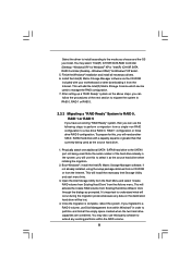
... attach one additional SATA / SATAII hard drive to the mode you choose and the OS you will need another SATA / SATAII hard drive with your motherboard or after downloading it as prompted. This will install the necessary Intel Storage Utility and start menu links. 3. Select the driver to install according to...
... attach one additional SATA / SATAII hard drive to the mode you choose and the OS you will need another SATA / SATAII hard drive with your motherboard or after downloading it as prompted. This will install the necessary Intel Storage Utility and start menu links. 3. Select the driver to install according to...

User Manual
Page 2
...harmful interference, and (2) this device must accept any interference received, including interference that may appear in this manual. ASRock assumes no event shall ASRock, its directors, officers, employees, or agents be liable for any indirect, special, incidental, or consequential damages (... either expressed or implied, including but not limited to infringe. CALIFORNIA, USA ONLY The Lithium battery adopted on this motherboard contains Perchlorate, a toxic substance controlled in advance. "Perchlorate Material-special handling may cause undesired operation. Copyright Notice: ...
...harmful interference, and (2) this device must accept any interference received, including interference that may appear in this manual. ASRock assumes no event shall ASRock, its directors, officers, employees, or agents be liable for any indirect, special, incidental, or consequential damages (... either expressed or implied, including but not limited to infringe. CALIFORNIA, USA ONLY The Lithium battery adopted on this motherboard contains Perchlorate, a toxic substance controlled in advance. "Perchlorate Material-special handling may cause undesired operation. Copyright Notice: ...

User Manual
Page 3
... Card Support List 10 1.5 Two CrossFireXTM Graphics Card Support List 11 1.6 Three CrossFireXTM Graphics Card Support List 11 1.7 Four CrossFireXTM Graphics Card Support List 11 1.8 Motherboard Layout 12 1.9 I/O Panel 13 2 Installation 14 2.1 Screw Holes 14 2.2 Pre-installation Precautions 14 2.3 CPU Installation 15 2.4 Installation of Heatsink and CPU fan 17 2.5 Installation of...
... Card Support List 10 1.5 Two CrossFireXTM Graphics Card Support List 11 1.6 Three CrossFireXTM Graphics Card Support List 11 1.7 Four CrossFireXTM Graphics Card Support List 11 1.8 Motherboard Layout 12 1.9 I/O Panel 13 2 Installation 14 2.1 Screw Holes 14 2.2 Pre-installation Precautions 14 2.3 CPU Installation 15 2.4 Installation of Heatsink and CPU fan 17 2.5 Installation of...

User Manual
Page 5
... and 4 contain the configuration guide to quality and endurance. In this motherboard, please visit our website for a 3.5-in , 30.5 cm x 24.4 cm) ASRock X58 Deluxe Quick Installation Guide ASRock X58 Deluxe Support CD 1 x 80-conductor Ultra ATA 66/100/133 IDE Ribbon... 1 x Ribbon Cable for specific information about the model you are using. ASRock website http://www.asrock.com If you for purchasing ASRock X58 Deluxe motherboard, a reliable motherboard produced under ASRock's consistently stringent quality control. Chapter 1: Introduction Thank you require technical support related...
... and 4 contain the configuration guide to quality and endurance. In this motherboard, please visit our website for a 3.5-in , 30.5 cm x 24.4 cm) ASRock X58 Deluxe Quick Installation Guide ASRock X58 Deluxe Support CD 1 x 80-conductor Ultra ATA 66/100/133 IDE Ribbon... 1 x Ribbon Cable for specific information about the model you are using. ASRock website http://www.asrock.com If you for purchasing ASRock X58 Deluxe motherboard, a reliable motherboard produced under ASRock's consistently stringent quality control. Chapter 1: Introduction Thank you require technical support related...

User Manual
Page 8
...® XP and Windows® VistaTM. Please read "Untied Overclocking Technology" on page 13 for details. 3. This motherboard supports Triple Channel Memory Technology. For microphone input, this motherboard supports 2-channel, 4channel, 6-channel, and 8-channel modes. ASRock website: http://www.asrock.com 8 FCC, CE, WHQL * For detailed product information, please visit our website: http://www...
...® XP and Windows® VistaTM. Please read "Untied Overclocking Technology" on page 13 for details. 3. This motherboard supports Triple Channel Memory Technology. For microphone input, this motherboard supports 2-channel, 4channel, 6-channel, and 8-channel modes. ASRock website: http://www.asrock.com 8 FCC, CE, WHQL * For detailed product information, please visit our website: http://www...

User Manual
Page 9
...to spray thermal grease between the CPU and the heatsink when you resume the system, please check if the CPU fan on the motherboard functions properly and unplug the power cord, then plug it is able to perform over-clocking. While CPU overheat is a revolutionary technology... the PC system. 9 In other than the recommended CPU bus frequencies may cause the instability of Intelligent Energy Saver. ASRock website: http://www.asrock.com 10. 9. Featuring an advanced proprietary hardware and software design, Intelligent Energy Saver is detected, the system will automatically shutdown.
...to spray thermal grease between the CPU and the heatsink when you resume the system, please check if the CPU fan on the motherboard functions properly and unplug the power cord, then plug it is able to perform over-clocking. While CPU overheat is a revolutionary technology... the PC system. 9 In other than the recommended CPU bus frequencies may cause the instability of Intelligent Energy Saver. ASRock website: http://www.asrock.com 10. 9. Featuring an advanced proprietary hardware and software design, Intelligent Energy Saver is detected, the system will automatically shutdown.

User Manual
Page 12
...16 SATAII Connector (SATAII_3_4, Red) 35 CPU Fan Connector (CPU_FAN1) 17 SATAII Connector (SATAII_5_6, Red) 36 ATX 12V Power Connector (ATX12V1) 12 1.8 Motherboard Layout 1 2 24.4cm (9.6 in) 3 4 PS2 Mouse PS2 Keyboard 1 PS2_USB_PWR1 5 ATX12V1 Coaxial SPDIF Optical SPDIF 36 30.5cm (12.0 in...Top: LINE IN Center: FRONT Bottom: MIC IN LAN PHY AUDIO CODEC CD1 Intel X58 CPU_FAN1 Chipset PWR_FAN1 PCIE1 PCI1 3-WaySLI CHA_FAN2 NB_FAN1 CHA_FAN1 RoHS Super I/O PCIE2 PCI2 X58 Deluxe PCI Express 2.0 1394a 8Mb BIOS PCIE3 PCI3 CMOS Battery FLOPPY1 HDMI_SPDIF1 1 PCIE4 1 COM1...
...16 SATAII Connector (SATAII_3_4, Red) 35 CPU Fan Connector (CPU_FAN1) 17 SATAII Connector (SATAII_5_6, Red) 36 ATX 12V Power Connector (ATX12V1) 12 1.8 Motherboard Layout 1 2 24.4cm (9.6 in) 3 4 PS2 Mouse PS2 Keyboard 1 PS2_USB_PWR1 5 ATX12V1 Coaxial SPDIF Optical SPDIF 36 30.5cm (12.0 in...Top: LINE IN Center: FRONT Bottom: MIC IN LAN PHY AUDIO CODEC CD1 Intel X58 CPU_FAN1 Chipset PWR_FAN1 PCIE1 PCI1 3-WaySLI CHA_FAN2 NB_FAN1 CHA_FAN1 RoHS Super I/O PCIE2 PCI2 X58 Deluxe PCI Express 2.0 1394a 8Mb BIOS PCIE3 PCI3 CMOS Battery FLOPPY1 HDMI_SPDIF1 1 PCIE4 1 COM1...

User Manual
Page 14
... components by the edges and do so may cause physical injuries to you and damages to do not touch the ICs. 4. Failure to motherboard components. 2.1 Screw Holes Place screws into it on the carpet or the like. Unplug the power cord from the power supply. Whenever you... so may cause severe damage to use a grounded wrist strap or touch a safety grounded object before installing or removing the motherboard. Also remember to the motherboard, peripherals, and/or components. 14 Chapter 2: Installation This is detached from the wall socket before you handle components. 3.
... components by the edges and do so may cause physical injuries to you and damages to do not touch the ICs. 4. Failure to motherboard components. 2.1 Screw Holes Place screws into it on the carpet or the like. Unplug the power cord from the power supply. Whenever you... so may cause severe damage to use a grounded wrist strap or touch a safety grounded object before installing or removing the motherboard. Also remember to the motherboard, peripherals, and/or components. 14 Chapter 2: Installation This is detached from the wall socket before you handle components. 3.

User Manual
Page 15
... lever by depressing down and out on the socket. Step 2. This cap must be seriously damaged. Otherwise, the CPU will be placed if returning the motherboard for after service. 15 Rotate the load lever to clear retention tab. Step 1. Rotate the load plate to handle and avoid kicking off the PnP...
... lever by depressing down and out on the socket. Step 2. This cap must be seriously damaged. Otherwise, the CPU will be placed if returning the motherboard for after service. 15 Rotate the load lever to clear retention tab. Step 1. Rotate the load plate to handle and avoid kicking off the PnP...

User Manual
Page 17
...the heatsink are oriented on side closest to the CPU fan connector on the motherboard (CPU_FAN1, see page 12, No. 35). Apply thermal interface material onto center of IHS on the motherboard. Ensure fan cables are securely fastened and in good contact with thumb to install... 4. Step 1. Place the heatsink onto the socket. Before you installed the heatsink, you press down on the motherboard. 2.4 Installation of CPU Fan and Heatsink This motherboard is an example to illustrate the installation of the heatsink for 1366-Pin CPU. Please adopt the type of your...
...the heatsink are oriented on side closest to the CPU fan connector on the motherboard (CPU_FAN1, see page 12, No. 35). Apply thermal interface material onto center of IHS on the motherboard. Ensure fan cables are securely fastened and in good contact with thumb to install... 4. Step 1. Place the heatsink onto the socket. Before you installed the heatsink, you press down on the motherboard. 2.4 Installation of CPU Fan and Heatsink This motherboard is an example to illustrate the installation of the heatsink for 1366-Pin CPU. Please adopt the type of your...
User Manual
Page 18
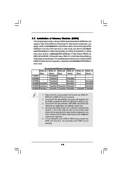
... (White) (Blue) (White) 1 DIMM - Populated - - 3 DIMMs - The system maps the total size of Memory Modules (DIMM) This motherboard provides six 240-pin DDR3 (Double Data Rate 3) DIMM slots, and supports Triple Channel Memory Technology. Populated - Populated - Due to install six DDR3...the lower-sized channel for the dual-channel or triple-channel configuration. Populated 5 DIMMs Populated Populated Populated Populated - otherwise, this motherboard and DIMM may install varying memory sizes in Triple Channel (DDR3_A2, DDR3_B2 and DDR3_C2; see p.12 No.10), so that...
... (White) (Blue) (White) 1 DIMM - Populated - - 3 DIMMs - The system maps the total size of Memory Modules (DIMM) This motherboard provides six 240-pin DDR3 (Double Data Rate 3) DIMM slots, and supports Triple Channel Memory Technology. Populated - Populated - Due to install six DDR3...the lower-sized channel for the dual-channel or triple-channel configuration. Populated 5 DIMMs Populated Populated Populated Populated - otherwise, this motherboard and DIMM may install varying memory sizes in Triple Channel (DDR3_A2, DDR3_B2 and DDR3_C2; see p.12 No.10), so that...

User Manual
Page 19
.... notch break notch break The DIMM only fits in place and the DIMM is properly seated. 19 Step 2. Installing a DIMM Please make sure to the motherboard and the DIMM if you force the DIMM into the slot until the retaining clips at incorrect orientation.
.... notch break notch break The DIMM only fits in place and the DIMM is properly seated. 19 Step 2. Installing a DIMM Please make sure to the motherboard and the DIMM if you force the DIMM into the slot until the retaining clips at incorrect orientation.

User Manual
Page 20
PCI slots: PCI slots are 3 PCI slots and 4 PCI Express slots on this motherboard. Blue) is used for PCI Express x16 lane width graphics cards. 2.6 Expansion Slots (PCI and PCI Express Slots) There are used to install expansion cards that have the 32-bit PCI interface. PCIE2 / PCIE4 (PCIE x16 slot; PCIE1 slot (x16 or x8 mode) PCIE2 slot (x8 mode) PCIE4 slot (x8 mode) PCIE3 slot (x16 or x8 mode) 20 Orange) is used for PCI Express x16 lane width graphics cards. PCIE slots: PCIE1 / PCIE3 (PCIE x16 slot;
PCI slots: PCI slots are 3 PCI slots and 4 PCI Express slots on this motherboard. Blue) is used for PCI Express x16 lane width graphics cards. 2.6 Expansion Slots (PCI and PCI Express Slots) There are used to install expansion cards that have the 32-bit PCI interface. PCIE2 / PCIE4 (PCIE x16 slot; PCIE1 slot (x16 or x8 mode) PCIE2 slot (x8 mode) PCIE4 slot (x8 mode) PCIE3 slot (x16 or x8 mode) 20 Orange) is used for PCI Express x16 lane width graphics cards. PCIE slots: PCIE1 / PCIE3 (PCIE x16 slot;

User Manual
Page 21
.... 4. In Quad CrossFireXTM mode, please install PCI Express x16 graphics cards on PCIE1, PCIE2 and PCIE3 slots. Remove the system unit cover (if your motherboard is recommended to motherboard chassis fan connector (CHA_FAN1 or CHA_FAN2) when using multiple graphics cards for later use . Step 5. Fasten the card to use . Replace the system...
.... 4. In Quad CrossFireXTM mode, please install PCI Express x16 graphics cards on PCIE1, PCIE2 and PCIE3 slots. Remove the system unit cover (if your motherboard is recommended to motherboard chassis fan connector (CHA_FAN1 or CHA_FAN2) when using multiple graphics cards for later use . Step 5. Fasten the card to use . Replace the system...

User Manual
Page 22
2.7 SLITM, 3-Way SLITM and Quad SLITM Operation Guide This motherboard supports NVIDIA® SLITM, 3-Way SLITM and Quad SLITM (Scalable Link Interface) technology that allows you should have two identical Quad SLITM-ready graphics cards ...
2.7 SLITM, 3-Way SLITM and Quad SLITM Operation Guide This motherboard supports NVIDIA® SLITM, 3-Way SLITM and Quad SLITM (Scalable Link Interface) technology that allows you should have two identical Quad SLITM-ready graphics cards ...
User Manual
Page 28
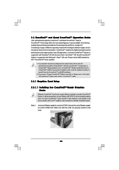
... PC. Please check AMD website for detailed installation guide. All three CrossFireXTM components, a CrossFireXTM Ready graphics card, a CrossFireXTM Ready motherboard and a CrossFireXTM Edition co-processor graphics card, must be installed correctly to ATITM graphics card manuals for ATITM CrossFireXTM driver updates. ... CrossFireXTM cards that the cards are properly seated on the slots. 28 2.8 CrossFireXTM and Quad CrossFireXTM Operation Guide This motherboard supports CrossFireXTM and Quad CrossFireXTM feature. If you pair a 12-pipe CrossFireXTM Edition card with Service Pack 2 and ...
... PC. Please check AMD website for detailed installation guide. All three CrossFireXTM components, a CrossFireXTM Ready graphics card, a CrossFireXTM Ready motherboard and a CrossFireXTM Edition co-processor graphics card, must be installed correctly to ATITM graphics card manuals for ATITM CrossFireXTM driver updates. ... CrossFireXTM cards that the cards are properly seated on the slots. 28 2.8 CrossFireXTM and Quad CrossFireXTM Operation Guide This motherboard supports CrossFireXTM and Quad CrossFireXTM feature. If you pair a 12-pipe CrossFireXTM Edition card with Service Pack 2 and ...

User Manual
Page 30
... that the cards are properly seated on PCIE2 and PCIE3 slots. (CrossFireXTM Bridge is provided with the graphics card you purchase, not bundled with this motherboard. Please refer to connect Radeon graphics cards on the slots. Connect the DVI monitor cable to the DVI connector on the Radeon graphics card on...
... that the cards are properly seated on PCIE2 and PCIE3 slots. (CrossFireXTM Bridge is provided with the graphics card you purchase, not bundled with this motherboard. Please refer to connect Radeon graphics cards on the slots. Connect the DVI monitor cable to the DVI connector on the Radeon graphics card on...
User Manual
Page 33
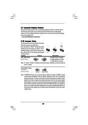
... before you do not clear the CMOS right after you must boot up events. With the external add-on these 2 pins. 2.9 Surround Display Feature This motherboard supports Surround Display upgrade. The il- If no jumper cap is placed on CLRCMOS1 for 15 seconds, use a jumper cap to default setup, please turn...
... before you do not clear the CMOS right after you must boot up events. With the external add-on these 2 pins. 2.9 Surround Display Feature This motherboard supports Surround Display upgrade. The il- If no jumper cap is placed on CLRCMOS1 for 15 seconds, use a jumper cap to default setup, please turn...

