User Manual
Page 2
... without intent to the implied warranties or conditions of the FCC Rules. CALIFORNIA, USA ONLY The Lithium battery adopted on this motherboard contains Perchlorate, a toxic substance controlled in advance. When you discard the Lithium battery in California, USA, please follow the related... (2) this device must accept any interference received, including interference that may apply, see www.dtsc.ca.gov/hazardouswaste/perchlorate" ASRock Website: http://www.asrock.com 2 Copyright Notice: No part of this manual may be reproduced, transcribed, transmitted, or translated in any language, in...
... without intent to the implied warranties or conditions of the FCC Rules. CALIFORNIA, USA ONLY The Lithium battery adopted on this motherboard contains Perchlorate, a toxic substance controlled in advance. When you discard the Lithium battery in California, USA, please follow the related... (2) this device must accept any interference received, including interference that may apply, see www.dtsc.ca.gov/hazardouswaste/perchlorate" ASRock Website: http://www.asrock.com 2 Copyright Notice: No part of this manual may be reproduced, transcribed, transmitted, or translated in any language, in...
User Manual
Page 3
Contents 1 Introduction 5 1.1 Package Contents 5 1.2 Specifications 6 1.3 Motherboard Layout 10 1.4 I/O Panel 11 2 Installation 12 2.1 Screw Holes 12 2.2 Pre-installation Precautions 12 2.3 Installation of Memory Modules (DIMM 13 2.4 Expansion Slot (PCI Slot 14 2.5 Jumpers ...
Contents 1 Introduction 5 1.1 Package Contents 5 1.2 Specifications 6 1.3 Motherboard Layout 10 1.4 I/O Panel 11 2 Installation 12 2.1 Screw Holes 12 2.2 Pre-installation Precautions 12 2.3 Installation of Memory Modules (DIMM 13 2.4 Expansion Slot (PCI Slot 14 2.5 Jumpers ...

User Manual
Page 5
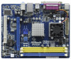
... our website for purchasing ASRock PV530 motherboard, a reliable motherboard produced under ASRock's consistently stringent quality control. You may find the latest VGA cards and CPU support lists on ASRock website without notice. www.asrock.com/support/index.asp 1.1 Package Contents ASRock PV530 Motherboard (Micro ATX Form Factor: 8.5-in x 6.7-in, 21.6 cm x 17.0 cm) ASRock PV530 Quick Installation Guide ASRock PV530 Support CD Two Serial...
... our website for purchasing ASRock PV530 motherboard, a reliable motherboard produced under ASRock's consistently stringent quality control. You may find the latest VGA cards and CPU support lists on ASRock website without notice. www.asrock.com/support/index.asp 1.1 Package Contents ASRock PV530 Motherboard (Micro ATX Form Factor: 8.5-in x 6.7-in, 21.6 cm x 17.0 cm) ASRock PV530 Quick Installation Guide ASRock PV530 Support CD Two Serial...

User Manual
Page 8
.... Before installing SATAII hard disk to the chipset limitation, the actual memory size may cause the instability of overclocking settings. CAUTION! 1. This motherboard supports Untied Overclocking Technology. Please read the "SATAII Hard Disk Setup Guide" on page 20 for details. 2. Please visit our website for ... 6. This convenient BIOS update tool allows you can save your OC settings as yours! With this motherboard offers stepless control, it is capable of ASRock OC Tuner. OC DNA literally tells you can press key during the POST or press key to BIOS setup menu to...
.... Before installing SATAII hard disk to the chipset limitation, the actual memory size may cause the instability of overclocking settings. CAUTION! 1. This motherboard supports Untied Overclocking Technology. Please read the "SATAII Hard Disk Setup Guide" on page 20 for details. 2. Please visit our website for ... 6. This convenient BIOS update tool allows you can save your OC settings as yours! With this motherboard offers stepless control, it is capable of ASRock OC Tuner. OC DNA literally tells you can press key during the POST or press key to BIOS setup menu to...
User Manual
Page 9
... for Energy Using Product, was a provision regulated by European Union to Intel's suggestion, the EuP ready power supply must meet EuP standard, an EuP ready motherboard and an EuP ready power supply are required. For EuP ready power supply selection, we recommend you checking with the power supply manufacturer for the...
... for Energy Using Product, was a provision regulated by European Union to Intel's suggestion, the EuP ready power supply must meet EuP standard, an EuP ready motherboard and an EuP ready power supply are required. For EuP ready power supply selection, we recommend you checking with the power supply manufacturer for the...

User Manual
Page 10
... SATAII Connector (SATAII_2; Yellow) (HD_AUDIO1, White) 7 1 x 240-pin DDR3 DIMM Slot (DDR3_1; Blue) 19 Primary SATAII Connector (SATAII_1; 1.3 Motherboard Layout 12 34 5 17.0cm (6.7 in) PWR_FAN1 1 PS2_USB_PWR1 PS2 Mouse PS2 Keyboard 67 COM1 CPU_FAN1 21.6cm (8.5 in) DDR3_1 (64 bit, 240...USB6_7 1 USB4_5 1 USB_PWR3 CLRCMOS1 CMOS Battery 4Mb BIOS PANEL 1 PLED PWRBTN SPEAKER1 1 1 HDLED RESET CHA_FAN1 15 14 13 12 11 RoHS PV530 8 9 10 1 Power Fan Connector (PWR_FAN1) 13 Chassis Speaker Header (SPEAKER 1, White) 2 PS2_USB_PWR1 Jumper 14 Clear CMOS Jumper (CLRCMOS1...
... SATAII Connector (SATAII_2; Yellow) (HD_AUDIO1, White) 7 1 x 240-pin DDR3 DIMM Slot (DDR3_1; Blue) 19 Primary SATAII Connector (SATAII_1; 1.3 Motherboard Layout 12 34 5 17.0cm (6.7 in) PWR_FAN1 1 PS2_USB_PWR1 PS2 Mouse PS2 Keyboard 67 COM1 CPU_FAN1 21.6cm (8.5 in) DDR3_1 (64 bit, 240...USB6_7 1 USB4_5 1 USB_PWR3 CLRCMOS1 CMOS Battery 4Mb BIOS PANEL 1 PLED PWRBTN SPEAKER1 1 1 HDLED RESET CHA_FAN1 15 14 13 12 11 RoHS PV530 8 9 10 1 Power Fan Connector (PWR_FAN1) 13 Chassis Speaker Header (SPEAKER 1, White) 2 PS2_USB_PWR1 Jumper 14 Clear CMOS Jumper (CLRCMOS1...
User Manual
Page 12
...cause severe damage to use a grounded wrist strap or touch a safety grounded object before installing or removing the motherboard. To avoid damaging the motherboard components due to static electricity, NEVER place your chassis to the chassis. Failure to do so may cause ...ICs. 4. Failure to unplug the power cord before you install the motherboard, study the configuration of the following precautions before touching any component, ensure that comes with the component. Chapter 2 Installation PV530 is detached from the wall socket before you install or remove any ...
...cause severe damage to use a grounded wrist strap or touch a safety grounded object before installing or removing the motherboard. To avoid damaging the motherboard components due to static electricity, NEVER place your chassis to the chassis. Failure to do so may cause ...ICs. 4. Failure to unplug the power cord before you install the motherboard, study the configuration of the following precautions before touching any component, ensure that comes with the component. Chapter 2 Installation PV530 is detached from the wall socket before you install or remove any ...
User Manual
Page 13
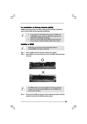
... the DIMM matches the break on the slot. Firmly insert the DIMM into the slot at the same time. 2.3 Installation of Memory Modules (DIMM) PV530 motherboard provides one correct orientation. You can choose to disconnect power supply before adding or removing DIMMs or the system components. Step 3. Please do not use...and DDR3 slot at incorrect orientation. notch break notch break The DIMM only fits in place and the DIMM is not allowed to the motherboard and the DIMM if you force the DIMM into the slot until the retaining clips at both ends fully snap back in one 240-pin...
... the DIMM matches the break on the slot. Firmly insert the DIMM into the slot at the same time. 2.3 Installation of Memory Modules (DIMM) PV530 motherboard provides one correct orientation. You can choose to disconnect power supply before adding or removing DIMMs or the system components. Step 3. Please do not use...and DDR3 slot at incorrect orientation. notch break notch break The DIMM only fits in place and the DIMM is not allowed to the motherboard and the DIMM if you force the DIMM into the slot until the retaining clips at both ends fully snap back in one 240-pin...

User Manual
Page 14
... the card is used to install expansion card that has the 32-bit PCI interface. Step 4. Remove the system unit cover (if your motherboard is unplugged. Replace the system cover. 14 Installing an expansion card Step 1. Align the card connector with screws. Step 6. Blue) is ...completely seated on this motherboard. Step 3. Fasten the card to use . 2.4 Expansion Slots (PCI and PCI Express Slots) There are 1 PCI slot and 1 PCI Express slot...
... the card is used to install expansion card that has the 32-bit PCI interface. Step 4. Remove the system unit cover (if your motherboard is unplugged. Replace the system cover. 14 Installing an expansion card Step 1. Align the card connector with screws. Step 6. Blue) is ...completely seated on this motherboard. Step 3. Fasten the card to use . 2.4 Expansion Slots (PCI and PCI Express Slots) There are 1 PCI slot and 1 PCI Express slot...
User Manual
Page 16
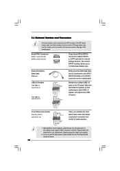
... SATAII or SATA hard disk for front panel audio cable that allows convenient connection and control of the motherboard! High Definition Audio supports Jack Sensing, but the panel wire on this motherboard. Each USB 2.0 header can be connected to install your system. 2. Placing jumper caps over these ...follow the instruction in our manual and chassis manual to the SATA / SATAII hard disk or the SATAII connector on the motherboard. 2.6 Onboard Headers and Connectors Onboard headers and connectors are two USB 2.0 headers on the chassis must support HDA to function correctly.
... SATAII or SATA hard disk for front panel audio cable that allows convenient connection and control of the motherboard! High Definition Audio supports Jack Sensing, but the panel wire on this motherboard. Each USB 2.0 header can be connected to install your system. 2. Placing jumper caps over these ...follow the instruction in our manual and chassis manual to the SATA / SATAII hard disk or the SATAII connector on the motherboard. 2.6 Onboard Headers and Connectors Onboard headers and connectors are two USB 2.0 headers on the chassis must support HDA to function correctly.

User Manual
Page 17
... HDLEDHDLED+ 1 SPEAKER DUMMY DUMMY +5V This header accommodates several system front panel functions. Connect Mic_IN (MIC) to the ground pin. Connect Ground (GND) to this motherboard provides 24-pin ATX power connector, it can still work if you adopt a traditional 20-pin ATX power supply. Please connect the chassis speaker to...
... HDLEDHDLED+ 1 SPEAKER DUMMY DUMMY +5V This header accommodates several system front panel functions. Connect Mic_IN (MIC) to the ground pin. Connect Ground (GND) to this motherboard provides 24-pin ATX power connector, it can still work if you adopt a traditional 20-pin ATX power supply. Please connect the chassis speaker to...
User Manual
Page 19
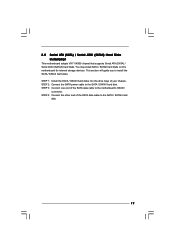
... 4: Connect the other end of the SATA data cable to the SATA / SATAII hard disk. 2.8 Serial ATA (SATA) / Serial ATAII (SATAII) Hard Disks Installation This motherboard adopts VIA® VX900 chipset that supports Serial ATA (SATA) / Serial ATAII (SATAII) hard disks. This section will guide you to the...
... 4: Connect the other end of the SATA data cable to the SATA / SATAII hard disk. 2.8 Serial ATA (SATA) / Serial ATAII (SATAII) Hard Disks Installation This motherboard adopts VIA® VX900 chipset that supports Serial ATA (SATA) / Serial ATAII (SATAII) hard disks. This section will guide you to the...

User Manual
Page 20
..., CPU FSB is untied during overclocking, but PCI buse is in the fixed mode so that FSB can work properly. 2.10 Untied Overclocking Technology This motherboard supports Untied Overclocking Technology, which means during overclocking, FSB enjoys better margin due to fixed PCI bus. Therefore, the drivers you apply Untied Overclocking Technology...
..., CPU FSB is untied during overclocking, but PCI buse is in the fixed mode so that FSB can work properly. 2.10 Untied Overclocking Technology This motherboard supports Untied Overclocking Technology, which means during overclocking, FSB enjoys better margin due to fixed PCI bus. Therefore, the drivers you apply Untied Overclocking Technology...

User Manual
Page 21
... by pressing + + , or by turning the system off and then back on your system. You may also restart by pressing the reset button on the motherboard stores the BIOS SETUP UTILITY. Chapter 3 BIOS SETUP UTILITY 3.1 Introduction This section explains how to use the BIOS SETUP UTILITY to configure your screen. 3.1.1 BIOS...
... by pressing + + , or by turning the system off and then back on your system. You may also restart by pressing the reset button on the motherboard stores the BIOS SETUP UTILITY. Chapter 3 BIOS SETUP UTILITY 3.1 Introduction This section explains how to use the BIOS SETUP UTILITY to configure your screen. 3.1.1 BIOS...

User Manual
Page 23
... [Auto], [400MHz DDR3_800] for DDR3 memory modules, or [Auto], [266MHz DDR2_533], [333MHz DDR2_667], [400MHz DDR2_800] for better system stability. The default value is selected, the motherboard will detect the memory module(s) inserted and assigns appropriate frequency automatically. CPU Frequency (MHz) Use this item to Sub Screen F1 General Help F9 Load...
... [Auto], [400MHz DDR3_800] for DDR3 memory modules, or [Auto], [266MHz DDR2_533], [333MHz DDR2_667], [400MHz DDR2_800] for better system stability. The default value is selected, the motherboard will detect the memory module(s) inserted and assigns appropriate frequency automatically. CPU Frequency (MHz) Use this item to Sub Screen F1 General Help F9 Load...

User Manual
Page 29
... Use this feature if the system supports it. Please set the power state after an unexpected AC/Power loss. Ring-In Power On Use this motherboard to enable or disable the feature Check Ready Bit. PS/2 Keyboard Power On Use this item to submit Windows® VistaTM certification. 29 Check Ready...
... Use this feature if the system supports it. Please set the power state after an unexpected AC/Power loss. Ring-In Power On Use this motherboard to enable or disable the feature Check Ready Bit. PS/2 Keyboard Power On Use this item to submit Windows® VistaTM certification. 29 Check Ready...

User Manual
Page 35
...], the CPU fan will operate in full speed. You can freely adjust the target fan speed according to identify the temperature of the CPU temperature, motherboard temperature, CPU fan speed, chassis fan speed, and the critical voltage. If you set this option as [Enabled], you will be between 45 C/113 F and...
...], the CPU fan will operate in full speed. You can freely adjust the target fan speed according to identify the temperature of the CPU temperature, motherboard temperature, CPU fan speed, chassis fan speed, and the critical voltage. If you set this option as [Enabled], you will be between 45 C/113 F and...

User Manual
Page 39
...or you need to contact ASRock or want to know more information. 4.2 Support CD Information The Support CD that came with the motherboard contains necessary drivers and useful utilities that the motherboard supports. Chapter 4 Software Support 4.1 Install Operating System This motherboard supports various Microsoft® ....EXE" from the BIN folder in this chapter for more about ASRock, welcome to activate the devices. 4.2.3 Utilities Menu The Utilities Menu shows the applications software that enhance the motherboard features. 4.2.1 Running The Support CD To begin using the support CD...
...or you need to contact ASRock or want to know more information. 4.2 Support CD Information The Support CD that came with the motherboard contains necessary drivers and useful utilities that the motherboard supports. Chapter 4 Software Support 4.1 Install Operating System This motherboard supports various Microsoft® ....EXE" from the BIN folder in this chapter for more about ASRock, welcome to activate the devices. 4.2.3 Utilities Menu The Utilities Menu shows the applications software that enhance the motherboard features. 4.2.1 Running The Support CD To begin using the support CD...

Quick Installation Guide
Page 1
... are used only for identification or explanation and to the owners' benefit, without notice, and should not be registered trademarks or copyrights of ASRock Inc. All rights reserved. 1 ASRock PV530 Motherboard English Operation is subject to the implied warranties or conditions of the FCC Rules. CALIFORNIA, USA ONLY The Lithium battery adopted on this...
... are used only for identification or explanation and to the owners' benefit, without notice, and should not be registered trademarks or copyrights of ASRock Inc. All rights reserved. 1 ASRock PV530 Motherboard English Operation is subject to the implied warranties or conditions of the FCC Rules. CALIFORNIA, USA ONLY The Lithium battery adopted on this...

Quick Installation Guide
Page 2
Motherboard Layout English 1 Power Fan Connector (PWR_FAN1) 13 Chassis Speaker Header (SPEAKER 1, White) 2 PS2_USB_PWR1 Jumper 14 Clear CMOS Jumper (CLRCMOS1) 3 ATX Power Connector (ATXPWR1) 15 PCI ... VX900 Chipset 10 BIOS SPI Chip 22 USB_PWR2 Jumper 11 Chassis Fan Connector (CHA_FAN1) 23 CPU Fan Connector (CPU_FAN1) 12 System Panel Header (PANEL1, White) 2 ASRock PV530 Motherboard Yellow) (HD_AUDIO1, White) 7 1 x 240-pin DDR3 DIMM Slot (DDR3_1; Blue) 19 Primary SATAII Connector (SATAII_1;
Motherboard Layout English 1 Power Fan Connector (PWR_FAN1) 13 Chassis Speaker Header (SPEAKER 1, White) 2 PS2_USB_PWR1 Jumper 14 Clear CMOS Jumper (CLRCMOS1) 3 ATX Power Connector (ATXPWR1) 15 PCI ... VX900 Chipset 10 BIOS SPI Chip 22 USB_PWR2 Jumper 11 Chassis Fan Connector (CHA_FAN1) 23 CPU Fan Connector (CPU_FAN1) 12 System Panel Header (PANEL1, White) 2 ASRock PV530 Motherboard Yellow) (HD_AUDIO1, White) 7 1 x 240-pin DDR3 DIMM Slot (DDR3_1; Blue) 19 Primary SATAII Connector (SATAII_1;


