User Manual
Page 6
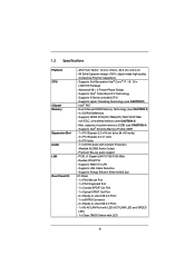
ATX Form Factor: 12.0-in x 9.6-in LGA1155 Package - Intel® P67 - Supports Wake-On-LAN - Supports LAN Cable Detection - Supports K-Series unlocked CPU - Dual Channel DDR3 Memory Technology (see CAUTION 4) - capacity of system memory: 32GB (...Port - 6 x Ready-to-Use USB 2.0 Ports - 1 x eSATA3 Connector - 2 x Ready-to-Use USB 3.0 Ports - 1 x RJ-45 LAN Port with LED (ACT/LINK LED and SPEED LED) - 1 x Clear CMOS Switch with Content Protection (Realtek ALC892 Audio Codec) - Supports Intel® Extreme Memory Profile (XMP) - 1 x PCI Express 2.0 x16 slot (blue @ x16 mode) - 3 x PCI...
ATX Form Factor: 12.0-in x 9.6-in LGA1155 Package - Intel® P67 - Supports Wake-On-LAN - Supports LAN Cable Detection - Supports K-Series unlocked CPU - Dual Channel DDR3 Memory Technology (see CAUTION 4) - capacity of system memory: 32GB (...Port - 6 x Ready-to-Use USB 2.0 Ports - 1 x eSATA3 Connector - 2 x Ready-to-Use USB 3.0 Ports - 1 x RJ-45 LAN Port with LED (ACT/LINK LED and SPEED LED) - 1 x Clear CMOS Switch with Content Protection (Realtek ALC892 Audio Codec) - Supports Intel® Extreme Memory Profile (XMP) - 1 x PCI Express 2.0 x16 slot (blue @ x16 mode) - 3 x PCI...

User Manual
Page 7
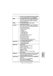
... (7-Segment Debug LED) - 1 x Clear CMOS Switch with LED - 1 x Power Switch with LED - 1 x Reset Switch with GUI support - Supports jumperfree - OEM and Trial; SMBIOS 2.3.1 Support - Instant Boot - Drivers, Utilities, AntiVirus Software (Trial Version), ASRock Software Suite (CyberLink DVD Suite - ASRock APP Charger (see CAUTION 7) - Creative...ACPI 1.1 Compliance Wake Up Events - DRAM, PCH, CPU PLL, VTT, VCCSA Voltage Multi-adjustment - ASRock Extreme Tuning Utility (AXTU) (see CAUTION 8) - Supports "Plug and Play" - SATA3 USB3.0 Connector Smart Switch BIOS Feature Support ...
... (7-Segment Debug LED) - 1 x Clear CMOS Switch with LED - 1 x Power Switch with LED - 1 x Reset Switch with GUI support - Supports jumperfree - OEM and Trial; SMBIOS 2.3.1 Support - Instant Boot - Drivers, Utilities, AntiVirus Software (Trial Version), ASRock Software Suite (CyberLink DVD Suite - ASRock APP Charger (see CAUTION 7) - Creative...ACPI 1.1 Compliance Wake Up Events - DRAM, PCH, CPU PLL, VTT, VCCSA Voltage Multi-adjustment - ASRock Extreme Tuning Utility (AXTU) (see CAUTION 8) - Supports "Plug and Play" - SATA3 USB3.0 Connector Smart Switch BIOS Feature Support ...

User Manual
Page 12
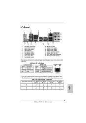
... SPK FRONT Bottom: CTR BASS Top: LINE IN Center: Bottom: MIC IN 38 37 PCIE1 P67 Pro3 RoHS 36 PCIE2 ErP/EuP Ready PCI Express 2.0 Designed in Taipei 35 PCIE3 CMOS 34 Battery Super I/O PCIE4 1 CLRCMOS1 33 AUDIO CODEC PCI1 USB 3.0 PCI2 USB8_9 CHA_FAN2 SATA3 6Gb... (CHA_FAN1) (Dual Channel: DDR3_A2, DDR3_B2, White) 28 Infrared Module Header (IR1) 7 ATX Power Connector (ATXPWR1) 29 Floppy Connector (FLOPPY1) 8 Clear CMOS Jumper (CLRCMOS1) 30 COM Port Header (COM1) 9 Chassis Fan Connector (CHA_FAN2) 31 Front Panel Audio Header 10 64Mb SPI Flash (HD_AUDIO1, White) ...
... SPK FRONT Bottom: CTR BASS Top: LINE IN Center: Bottom: MIC IN 38 37 PCIE1 P67 Pro3 RoHS 36 PCIE2 ErP/EuP Ready PCI Express 2.0 Designed in Taipei 35 PCIE3 CMOS 34 Battery Super I/O PCIE4 1 CLRCMOS1 33 AUDIO CODEC PCI1 USB 3.0 PCI2 USB8_9 CHA_FAN2 SATA3 6Gb... (CHA_FAN1) (Dual Channel: DDR3_A2, DDR3_B2, White) 28 Infrared Module Header (IR1) 7 ATX Power Connector (ATXPWR1) 29 Floppy Connector (FLOPPY1) 8 Clear CMOS Jumper (CLRCMOS1) 30 COM Port Header (COM1) 9 Chassis Fan Connector (CHA_FAN2) 31 Front Panel Audio Header 10 64Mb SPI Flash (HD_AUDIO1, White) ...

User Manual
Page 13
... 10 Microphone (Pink) 11 USB 2.0 Ports (USB01) 12 USB 3.0 Ports (USB23) 13 USB 2.0 Ports (USB45) 14 eSATA3 Connector (eSATA3) 15 Optical SPDIF Out Port 16 Clear CMOS Switch (CLRCBTN) 17 PS/2 Keyboard Port (Purple) * There are two LED next to the table below for connection details in accordance with the type of...
... 10 Microphone (Pink) 11 USB 2.0 Ports (USB01) 12 USB 3.0 Ports (USB23) 13 USB 2.0 Ports (USB45) 14 eSATA3 Connector (eSATA3) 15 Optical SPDIF Out Port 16 Clear CMOS Switch (CLRCBTN) 17 PS/2 Keyboard Port (Purple) * There are two LED next to the table below for connection details in accordance with the type of...

User Manual
Page 22
...pins, the jumper is "Short". When the jumper cap is placed on CLRCMOS1 for 5 seconds. To clear and reset the system parameters to clear the data in CMOS. If you need to clear the CMOS when you just finish updating the BIOS, you must boot up the system first, ...date, time, user default profile, 1394 GUID and MAC address will be cleared only if the CMOS battery is "Open". The Clear CMOS Switch has the same function as the Clear CMOS jumper. 22 However, please do the clear-CMOS action. 2.7 Jumpers Setup The illustration shows how jumpers are "Short" when jumper cap ...
...pins, the jumper is "Short". When the jumper cap is placed on CLRCMOS1 for 5 seconds. To clear and reset the system parameters to clear the data in CMOS. If you need to clear the CMOS when you just finish updating the BIOS, you must boot up the system first, ...date, time, user default profile, 1394 GUID and MAC address will be cleared only if the CMOS battery is "Open". The Clear CMOS Switch has the same function as the Clear CMOS jumper. 22 However, please do the clear-CMOS action. 2.7 Jumpers Setup The illustration shows how jumpers are "Short" when jumper cap ...

User Manual
Page 28
.... Power Switch (PWRBTN) (see p.12 No. 22) RESET Reset Switch is a smart switch, allowing users to quickly clear the CMOS values. 28 2.9 Smart Switches The motherboard has three smart switches: power switch, reset switch and clear CMOS switch, allowing users to quickly reset the system. Reset Switch (RSTBTN) (see p.12 No. 23) Power Switch...
.... Power Switch (PWRBTN) (see p.12 No. 22) RESET Reset Switch is a smart switch, allowing users to quickly clear the CMOS values. 28 2.9 Smart Switches The motherboard has three smart switches: power switch, reset switch and clear CMOS switch, allowing users to quickly reset the system. Reset Switch (RSTBTN) (see p.12 No. 23) Power Switch...

Quick Installation Guide
Page 2
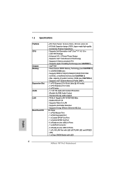
... DIMM Slots 27 Chassis Fan Connector (CHA_FAN1) (Dual Channel: DDR3_A2, DDR3_B2, White) 28 Infrared Module Header (IR1) 7 ATX Power Connector (ATXPWR1) 29 Floppy Connector (FLOPPY1) 8 Clear CMOS Jumper (CLRCMOS1) 30 COM Port Header (COM1) 9 Chassis Fan Connector (CHA_FAN2) 31 Front Panel Audio Header 10 64Mb SPI Flash (HD_AUDIO1, White) 11 Power LED... SATA2 Connector (SATA2_2, Blue) 38 Chassis Fan Connector (CHA_FAN3) 19 SATA2 Connector (SATA2_4, Blue) 39 Power Fan Connector (PWR_FAN1) 20 SATA2 Connector (SATA2_5, Blue) English 2 ASRock P67 Pro3 Motherboard
... DIMM Slots 27 Chassis Fan Connector (CHA_FAN1) (Dual Channel: DDR3_A2, DDR3_B2, White) 28 Infrared Module Header (IR1) 7 ATX Power Connector (ATXPWR1) 29 Floppy Connector (FLOPPY1) 8 Clear CMOS Jumper (CLRCMOS1) 30 COM Port Header (COM1) 9 Chassis Fan Connector (CHA_FAN2) 31 Front Panel Audio Header 10 64Mb SPI Flash (HD_AUDIO1, White) 11 Power LED... SATA2 Connector (SATA2_2, Blue) 38 Chassis Fan Connector (CHA_FAN3) 19 SATA2 Connector (SATA2_4, Blue) 39 Power Fan Connector (PWR_FAN1) 20 SATA2 Connector (SATA2_5, Blue) English 2 ASRock P67 Pro3 Motherboard
Quick Installation Guide
Page 3
...2.0 Ports (USB01) 12 USB 3.0 Ports (USB23) 13 USB 2.0 Ports (USB45) 14 eSATA3 Connector (eSATA3) 15 Optical SPDIF Out Port 16 Clear CMOS Switch (CLRCBTN) 17 PS/2 Keyboard Port (Purple) * There are two LED next to the table below for connection details in accordance with the ...Output Connection Audio Output Channels Front Speaker Rear Speaker Central / Bass Side Speaker (No. 9) (No. 6) (No. 7) (No. 5) 2 V -- -- -- 4 V V -- -- 6 V V V -- 8 V V V V English 3 ASRock P67 Pro3 Motherboard TABLE for the LAN port LED indications. Please refer to the LAN port.
...2.0 Ports (USB01) 12 USB 3.0 Ports (USB23) 13 USB 2.0 Ports (USB45) 14 eSATA3 Connector (eSATA3) 15 Optical SPDIF Out Port 16 Clear CMOS Switch (CLRCBTN) 17 PS/2 Keyboard Port (Purple) * There are two LED next to the table below for connection details in accordance with the ...Output Connection Audio Output Channels Front Speaker Rear Speaker Central / Bass Side Speaker (No. 9) (No. 6) (No. 7) (No. 5) 2 V -- -- -- 4 V V -- -- 6 V V V -- 8 V V V V English 3 ASRock P67 Pro3 Motherboard TABLE for the LAN port LED indications. Please refer to the LAN port.
Quick Installation Guide
Page 6
... x PCI Express 2.0 x16 slot (blue @ x16 mode) - 3 x PCI Express 2.0 x1 slots - 3 x PCI slots - 7.1 CH HD Audio with LED English 6 ASRock P67 Pro3 Motherboard ATX Form Factor: 12.0-in x 9.6-in LGA1155 Package - Max. 1.2 Specifications Platform CPU Chipset Memory Expansion Slot Audio LAN Rear Panel I /O Panel - 1 x PS/2 ...1 x eSATA3 Connector - 2 x Ready-to-Use USB 3.0 Ports - 1 x RJ-45 LAN Port with LED (ACT/LINK LED and SPEED LED) - 1 x Clear CMOS Switch with Content Protection (Realtek ALC892 Audio Codec) - PCIE x1 Gigabit LAN 10/100/1000 Mb/s - Supports K-Series unlocked CPU -
... x PCI Express 2.0 x16 slot (blue @ x16 mode) - 3 x PCI Express 2.0 x1 slots - 3 x PCI slots - 7.1 CH HD Audio with LED English 6 ASRock P67 Pro3 Motherboard ATX Form Factor: 12.0-in x 9.6-in LGA1155 Package - Max. 1.2 Specifications Platform CPU Chipset Memory Expansion Slot Audio LAN Rear Panel I /O Panel - 1 x PS/2 ...1 x eSATA3 Connector - 2 x Ready-to-Use USB 3.0 Ports - 1 x RJ-45 LAN Port with LED (ACT/LINK LED and SPEED LED) - 1 x Clear CMOS Switch with Content Protection (Realtek ALC892 Audio Codec) - PCIE x1 Gigabit LAN 10/100/1000 Mb/s - Supports K-Series unlocked CPU -
Quick Installation Guide
Page 7
... ports) - 1 x Dr. Debug (7-Segment Debug LED) - 1 x Clear CMOS Switch with LED - 1 x Power Switch with LED - 1 x Reset Switch with GUI support - Drivers, Utilities, AntiVirus Software (Trial Version), ASRock Software Suite (CyberLink DVD Suite - SATA3 USB3.0 Connector Smart Switch BIOS Feature Support... CD Unique Feature - HD Audio Jack: Side Speaker/Rear Speaker/Central/Bass/ Line in/Front Speaker/Microphone (see CAUTION 6) - ASRock APP Charger (see CAUTION 9) 7 ASRock P67 Pro3 ...
... ports) - 1 x Dr. Debug (7-Segment Debug LED) - 1 x Clear CMOS Switch with LED - 1 x Power Switch with LED - 1 x Reset Switch with GUI support - Drivers, Utilities, AntiVirus Software (Trial Version), ASRock Software Suite (CyberLink DVD Suite - SATA3 USB3.0 Connector Smart Switch BIOS Feature Support... CD Unique Feature - HD Audio Jack: Side Speaker/Rear Speaker/Central/Bass/ Line in/Front Speaker/Microphone (see CAUTION 6) - ASRock APP Charger (see CAUTION 9) 7 ASRock P67 Pro3 ...

Quick Installation Guide
Page 18
... reset the system parameters to short pin2 and pin3 on pins, the jumper is "Open". However, please do the clear-CMOS action. English 18 ASRock P67 Pro3 Motherboard After waiting for 5 seconds. 2.5 Jumpers Setup The illustration shows how jumpers are "Short" when jumper cap is placed on pins, the jumper is "Short". ...
... reset the system parameters to short pin2 and pin3 on pins, the jumper is "Open". However, please do the clear-CMOS action. English 18 ASRock P67 Pro3 Motherboard After waiting for 5 seconds. 2.5 Jumpers Setup The illustration shows how jumpers are "Short" when jumper cap is placed on pins, the jumper is "Short". ...

Quick Installation Guide
Page 24
English 24 ASRock P67 Pro3 Motherboard Clear CMOS Switch (CLRCBTN) (see p.2 No. 22) RESET Reset Switch is a smart switch, allowing users to quickly reset the system. Reset Switch (RSTBTN) (see p.3 No. 16) clr CMOS Clear CMOS Switch is a smart switch, allowing users to quickly turn on /off or reset the sytem clear the CMOS values. Power Switch (PWRBTN) (see p.2 No. 23...
English 24 ASRock P67 Pro3 Motherboard Clear CMOS Switch (CLRCBTN) (see p.2 No. 22) RESET Reset Switch is a smart switch, allowing users to quickly reset the system. Reset Switch (RSTBTN) (see p.3 No. 16) clr CMOS Clear CMOS Switch is a smart switch, allowing users to quickly turn on /off or reset the sytem clear the CMOS values. Power Switch (PWRBTN) (see p.2 No. 23...

Quick Installation Guide
Page 190
2.5 3 1-2 점퍼 CMOS 초기화 (CLRCMOS1, 3 2 8 세팅 CMOS 삭제 참고 : CLRCMOS1 CMOS 15 CLRCMOS1 의 핀 2 와 핀 3 을 5 BIOS CMOS BIOS CMOS CMOS CMOS 1394 GUID, MAC Clear CMOS Switch는 Clear CMOS 한 국 어 190 ASRock P67 Pro3 Motherboard
2.5 3 1-2 점퍼 CMOS 초기화 (CLRCMOS1, 3 2 8 세팅 CMOS 삭제 참고 : CLRCMOS1 CMOS 15 CLRCMOS1 의 핀 2 와 핀 3 을 5 BIOS CMOS BIOS CMOS CMOS CMOS 1394 GUID, MAC Clear CMOS Switch는 Clear CMOS 한 국 어 190 ASRock P67 Pro3 Motherboard

Quick Installation Guide
Page 257
2.5 3 1 和針腳 2 CMOS (CLRCMOS1, 3 2 頁第 8 項 ) 設定 默認設置 清除 CMOS 註: C L R C M O S1 C M O S 15 CLRCMOS1 的 pin2 及 pin3 短路 5 BIOS CMOS BIOS CMOS CMOS C M O S 1394 GUID 及 MAC Clear CMOS Clear CMOS 繁體中文 257 ASRock P67 Pro3 Motherboard
2.5 3 1 和針腳 2 CMOS (CLRCMOS1, 3 2 頁第 8 項 ) 設定 默認設置 清除 CMOS 註: C L R C M O S1 C M O S 15 CLRCMOS1 的 pin2 及 pin3 短路 5 BIOS CMOS BIOS CMOS CMOS C M O S 1394 GUID 及 MAC Clear CMOS Clear CMOS 繁體中文 257 ASRock P67 Pro3 Motherboard

