User Manual
Page 10
...to ASRock of charging your PC games. ASRock website: http://www.asrock.com...ASRock AIWI is IE8. If you resume the system, please check if the CPU fan on -the-go. ASRock...as iPhone/iPod/iPad Touch, ASRock has prepared a wonderful solution...to install the ASRock AIWI utility either from ASRock of internet browser... of ficial website or ASRock software support CD to do -date...ASRock website: http://www.asrock.com/Feature/ SmartView/index.asp 11. Although this motherboard offers stepless control, it back again. ASRock motherboards... have to your motherboard, and also download the...
...to ASRock of charging your PC games. ASRock website: http://www.asrock.com...ASRock AIWI is IE8. If you resume the system, please check if the CPU fan on -the-go. ASRock...as iPhone/iPod/iPad Touch, ASRock has prepared a wonderful solution...to install the ASRock AIWI utility either from ASRock of internet browser... of ficial website or ASRock software support CD to do -date...ASRock website: http://www.asrock.com/Feature/ SmartView/index.asp 11. Although this motherboard offers stepless control, it back again. ASRock motherboards... have to your motherboard, and also download the...

User Manual
Page 12
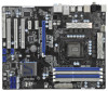
1.3 Motherboard Layout 1 2 34 24.4cm (9.6 in) ATX12V1 CPU_FAN2 CPU_FAN1 PS2 Mouse 5 6 ...: PWR_FAN1 CHA_FAN3 REAR SPK FRONT Bottom: CTR BASS Top: LINE IN Center: Bottom: MIC IN 38 37 PCIE1 P67 Pro3 RoHS 36 PCIE2 ErP/EuP Ready PCI Express 2.0 Designed in Taipei 35 PCIE3 CMOS 34 Battery Super I/O PCIE4 ...21 Dr. Debug 2 CPU Fan Connector (CPU_FAN2) 22 Reset Switch (RSTBTN) 3 CPU Fan Connector (CPU_FAN1) 23 Power Switch (PWRBTN) 4 1155-Pin CPU Socket 24 USB 2.0 Header (USB12_13, Blue) 5 2 x 240-pin DDR3 DIMM Slots 25 USB 2.0 Header (USB8_9, Blue) (Dual Channel: ...
1.3 Motherboard Layout 1 2 34 24.4cm (9.6 in) ATX12V1 CPU_FAN2 CPU_FAN1 PS2 Mouse 5 6 ...: PWR_FAN1 CHA_FAN3 REAR SPK FRONT Bottom: CTR BASS Top: LINE IN Center: Bottom: MIC IN 38 37 PCIE1 P67 Pro3 RoHS 36 PCIE2 ErP/EuP Ready PCI Express 2.0 Designed in Taipei 35 PCIE3 CMOS 34 Battery Super I/O PCIE4 ...21 Dr. Debug 2 CPU Fan Connector (CPU_FAN2) 22 Reset Switch (RSTBTN) 3 CPU Fan Connector (CPU_FAN1) 23 Power Switch (PWRBTN) 4 1155-Pin CPU Socket 24 USB 2.0 Header (USB12_13, Blue) 5 2 x 240-pin DDR3 DIMM Slots 25 USB 2.0 Header (USB8_9, Blue) (Dual Channel: ...
User Manual
Page 16
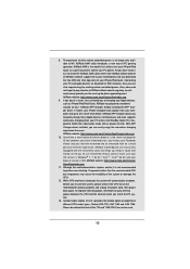
...Load Lever Contact Array Socket Body 1155-Pin Socket Overview Before you insert the 1155-Pin CPU into the socket if above situation is found. Step 1-2. Rotate the load plate to fully open position at approximately 135 degrees. Step 1. 2.3 CPU Installation For the installation of Intel 1155-Pin CPU, please ...PnP cap. 2. Otherwise, the CPU will be placed if returning the motherboard for after service. 16 This cap must be seriously damaged. Step 1-3. Do not force to insert the CPU into the socket, please check if the CPU surface is unclean or if there is recommended...
...Load Lever Contact Array Socket Body 1155-Pin Socket Overview Before you insert the 1155-Pin CPU into the socket if above situation is found. Step 1-2. Rotate the load plate to fully open position at approximately 135 degrees. Step 1. 2.3 CPU Installation For the installation of Intel 1155-Pin CPU, please ...PnP cap. 2. Otherwise, the CPU will be placed if returning the motherboard for after service. 16 This cap must be seriously damaged. Step 1-3. Do not force to insert the CPU into the socket, please check if the CPU surface is unclean or if there is recommended...

User Manual
Page 18
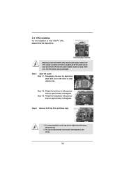
.... Below is equipped with tie-wrap to illustrate the installation of IHS on the motherboard. Apply Thermal Interface Material Step 2. Step 3. Secure excess cable with 1155-Pin socket that supports Intel 1155-Pin CPU. Fan cables on side closest to adopt three different CPU cooler types..., Socket LGA 775, LGA 1155 and LGA 1156. Please be secured on the motherboard (CPU_ FAN1, see page 12, No. 3). Ensure that this motherboard supports Combo Cooler Option (C.C.O.), which provides the flexible option to...
.... Below is equipped with tie-wrap to illustrate the installation of IHS on the motherboard. Apply Thermal Interface Material Step 2. Step 3. Secure excess cable with 1155-Pin socket that supports Intel 1155-Pin CPU. Fan cables on side closest to adopt three different CPU cooler types..., Socket LGA 775, LGA 1155 and LGA 1156. Please be secured on the motherboard (CPU_ FAN1, see page 12, No. 3). Ensure that this motherboard supports Combo Cooler Option (C.C.O.), which provides the flexible option to...

Quick Installation Guide
Page 2
...PWR_FAN1 CHA_FAN3 REAR SPK FRONT Bottom: CTR BASS Top: LINE IN Center: Bottom: MIC IN 38 37 PCIE1 P67 Pro3 RoHS 36 PCIE2 ErP/EuP Ready PCI Express 2.0 Designed in Taipei 35 PCIE3 CMOS 34 Battery Super I/O ...Dr. Debug 2 CPU Fan Connector (CPU_FAN2) 22 Reset Switch (RSTBTN) 3 CPU Fan Connector (CPU_FAN1) 23 Power Switch (PWRBTN) 4 1155-Pin CPU Socket 24 USB 2.0 Header (USB12_13, Blue) 5 2 x 240-pin DDR3 DIMM Slots 25 USB 2.0 Header (USB8_9, Blue) (Dual Channel:...39 Power Fan Connector (PWR_FAN1) 20 SATA2 Connector (SATA2_5, Blue) English 2 ASRock P67 Pro3 Motherboard
...PWR_FAN1 CHA_FAN3 REAR SPK FRONT Bottom: CTR BASS Top: LINE IN Center: Bottom: MIC IN 38 37 PCIE1 P67 Pro3 RoHS 36 PCIE2 ErP/EuP Ready PCI Express 2.0 Designed in Taipei 35 PCIE3 CMOS 34 Battery Super I/O ...Dr. Debug 2 CPU Fan Connector (CPU_FAN2) 22 Reset Switch (RSTBTN) 3 CPU Fan Connector (CPU_FAN1) 23 Power Switch (PWRBTN) 4 1155-Pin CPU Socket 24 USB 2.0 Header (USB12_13, Blue) 5 2 x 240-pin DDR3 DIMM Slots 25 USB 2.0 Header (USB8_9, Blue) (Dual Channel:...39 Power Fan Connector (PWR_FAN1) 20 SATA2 Connector (SATA2_5, Blue) English 2 ASRock P67 Pro3 Motherboard

Quick Installation Guide
Page 10
...! Please be used. 10 ASRock P67 Pro3 Motherboard English ASRock AIWI utility introduces a new way of ficial website or ASRock software support CD to your Apple devices, such as a game joystick to adopt three different CPU cooler types, Socket LGA 775, LGA 1155 and LGA 1156. ASRock AIWI is just to ASRock of charging your motherboard, and also download the...
...! Please be used. 10 ASRock P67 Pro3 Motherboard English ASRock AIWI utility introduces a new way of ficial website or ASRock software support CD to your Apple devices, such as a game joystick to adopt three different CPU cooler types, Socket LGA 775, LGA 1155 and LGA 1156. ASRock AIWI is just to ASRock of charging your motherboard, and also download the...

Quick Installation Guide
Page 12
... is found. erboard to the motherboard, peripherals, and/or components. 2. Do not force to static electricity, NEVER place your motherboard directly on the carpet or the like. Load Plate Contact Array Load Lever Socket Body 1155-Pin Socket Overview Before you uninstall any bent... component, place it on the socket. Otherwise, the CPU will be seriously damaged. Unplug the power cord from the wall socket before you handle components. 3. English 12 ASRock P67 Pro3 Motherboard Installation Pre-installation Precautions Take note of Intel 1155-Pin CPU, please follow the ...
... is found. erboard to the motherboard, peripherals, and/or components. 2. Do not force to static electricity, NEVER place your motherboard directly on the carpet or the like. Load Plate Contact Array Load Lever Socket Body 1155-Pin Socket Overview Before you uninstall any bent... component, place it on the socket. Otherwise, the CPU will be seriously damaged. Unplug the power cord from the wall socket before you handle components. 3. English 12 ASRock P67 Pro3 Motherboard Installation Pre-installation Precautions Take note of Intel 1155-Pin CPU, please follow the ...

Quick Installation Guide
Page 13
... fully open position at approximately 135 degrees. Rotate the load plate to match the two orientation key notches of the socket. 13 ASRock P67 Pro3 Motherboard English Remove PnP Cap (Pick and Place Cap). 1. Insert the 1155-Pin CPU: Step 3-1. Orient the CPU with the two alignment keys of the CPU with IHS (Integrated Heat Sink...
... fully open position at approximately 135 degrees. Rotate the load plate to match the two orientation key notches of the socket. 13 ASRock P67 Pro3 Motherboard English Remove PnP Cap (Pick and Place Cap). 1. Insert the 1155-Pin CPU: Step 3-1. Orient the CPU with the two alignment keys of the CPU with IHS (Integrated Heat Sink...

Quick Installation Guide
Page 14
... Fan and Heatsink For proper installation, please kindly refer to illustrate the installation of the heatsink for Socket LGA 1155/1156 CPU fan. 14 ASRock P67 Pro3 Motherboard English Connect fan header with the CPU fan connector on the socket surface. Secure excess cable with fan operation or contact other components. Step 3-4. While pressing down the fasteners...
... Fan and Heatsink For proper installation, please kindly refer to illustrate the installation of the heatsink for Socket LGA 1155/1156 CPU fan. 14 ASRock P67 Pro3 Motherboard English Connect fan header with the CPU fan connector on the socket surface. Secure excess cable with fan operation or contact other components. Step 3-4. While pressing down the fasteners...

Quick Installation Guide
Page 184
2 1 2 3 IC 4 5 2.1 CPU 설치 Intel 1155 핀 CPU 장착판 Load Plate Load Lever Contact Array Socket Body 1155 1155 핀 CPU CPU CPU CPU 한 국 어 184 ASRock P67 Pro3 Motherboard
2 1 2 3 IC 4 5 2.1 CPU 설치 Intel 1155 핀 CPU 장착판 Load Plate Load Lever Contact Array Socket Body 1155 1155 핀 CPU CPU CPU CPU 한 국 어 184 ASRock P67 Pro3 Motherboard

Quick Installation Guide
Page 207
IC 4. 2.1 CPU Intel 1155-LAND CPU Load Plate Load Lever Contact Array Socket Body 1155 1155-LAND CPU CPU CPU CPU 1 1-1 日本語 207 ASRock P67 Pro3 Motherboard 1. 2. 3.
IC 4. 2.1 CPU Intel 1155-LAND CPU Load Plate Load Lever Contact Array Socket Body 1155 1155-LAND CPU CPU CPU CPU 1 1-1 日本語 207 ASRock P67 Pro3 Motherboard 1. 2. 3.

Quick Installation Guide
Page 209
4 4-1 HIS 4-2 4-3 2.2 CPU CPU 以下は、1155-LAND CPU 1 HIS Apply Thermal Interface Material 2 CPU_FAN1、2 No. 3 CPU 3 4 Fan cables on side closest to MB header Fastener slots pointing straight out Press Down (4 Places) 5 CPU 6 C.C.O Socket LGA 775、LGA 1155 と LGA 1156 の 3 CPU Socket LGA 1155/1156 CPU 日本語 209 ASRock P67 Pro3 Motherboard
4 4-1 HIS 4-2 4-3 2.2 CPU CPU 以下は、1155-LAND CPU 1 HIS Apply Thermal Interface Material 2 CPU_FAN1、2 No. 3 CPU 3 4 Fan cables on side closest to MB header Fastener slots pointing straight out Press Down (4 Places) 5 CPU 6 C.C.O Socket LGA 775、LGA 1155 と LGA 1156 の 3 CPU Socket LGA 1155/1156 CPU 日本語 209 ASRock P67 Pro3 Motherboard

Quick Installation Guide
Page 229
2 安全防范 1 2 3 4 5 2.1 CPU 安裝 要安裝 Intel 1155 針 CPU Load Plate Contact Array Load Lever Socket Body 1155 在您將 1155 針 CPU CPU CPU CPU 步驟 1. 1-1 簡體中文 229 ASRock P67 Pro3 Motherboard
2 安全防范 1 2 3 4 5 2.1 CPU 安裝 要安裝 Intel 1155 針 CPU Load Plate Contact Array Load Lever Socket Body 1155 在您將 1155 針 CPU CPU CPU CPU 步驟 1. 1-1 簡體中文 229 ASRock P67 Pro3 Motherboard

Quick Installation Guide
Page 251
2 安全防範 1 2 3 4 5 2.1 CPU 安裝 要安裝 Intel 1155 針 CPU Load Plate Contact Array Load Lever Socket Body ( 插槽 ) 1155 在您將 1155 針 CPU CPU CPU CPU 步驟 1. 1-1 繁體中文 251 ASRock P67 Pro3 Motherboard
2 安全防範 1 2 3 4 5 2.1 CPU 安裝 要安裝 Intel 1155 針 CPU Load Plate Contact Array Load Lever Socket Body ( 插槽 ) 1155 在您將 1155 針 CPU CPU CPU CPU 步驟 1. 1-1 繁體中文 251 ASRock P67 Pro3 Motherboard


