RAID Installation Guide
Page 2
For SATA installation guide, please refer to SATA Hard Disks Installation 1.1 Serial ATA (SATA) Hard Disks Installation Intel P55 southbridge chipset supports Serial ATA (SATA) hard disks with RAID functions, including RAID 0, RAID 1, RAID 10, RAID 5, and Intel Matrix Storage. This ...section will guide you how to create RAID on this guide carefully according to the Intel southbridge chipset that your motherboard adopts. Please read the RAID configurations in the support CD. Guide to Serial ATA (SATA) Hard Disks Installation of "User...
For SATA installation guide, please refer to SATA Hard Disks Installation 1.1 Serial ATA (SATA) Hard Disks Installation Intel P55 southbridge chipset supports Serial ATA (SATA) hard disks with RAID functions, including RAID 0, RAID 1, RAID 10, RAID 5, and Intel Matrix Storage. This ...section will guide you how to create RAID on this guide carefully according to the Intel southbridge chipset that your motherboard adopts. Please read the RAID configurations in the support CD. Guide to Serial ATA (SATA) Hard Disks Installation of "User...
RAID Installation Guide
Page 3
... surviving drive as a single drive but at a sustained data transfer rate. For optimal performance, please install identical drives of RAID This motherboard adopts Intel southbridge chipset that integrates RAID controller supporting RAID 0 / RAID 1/ Intel Matrix Storage / RAID 10 / RAID 5 function with six independent Serial ATA (SATA) channels. RAID 1 (Data Mirroring) RAID...
... surviving drive as a single drive but at a sustained data transfer rate. For optimal performance, please install identical drives of RAID This motherboard adopts Intel southbridge chipset that integrates RAID controller supporting RAID 0 / RAID 1/ Intel Matrix Storage / RAID 10 / RAID 5 function with six independent Serial ATA (SATA) channels. RAID 1 (Data Mirroring) RAID...

User Manual
Page 4
... SETUP UTILITY 54 3.1 Introduction 54 3.1.1 BIOS Menu Bar 54 3.1.2 Navigation Keys 55 3.2 Main Screen 55 3.3 OC Tweaker Screen 56 3.4 Advanced Screen 59 3.4.1 CPU Configuration 60 3.4.2 Chipset Configuration 62 3.4.3 ACPI Configuration 63 3.4.4 IDE Configuration 64 3.4.5 PCIPnP Configuration 66 3.4.6 Floppy Configuration 67 3.4.7 Super IO Configuration 67 3.4.8 USB Configuration 68 3.5 Hardware Health Event Monitoring...
... SETUP UTILITY 54 3.1 Introduction 54 3.1.1 BIOS Menu Bar 54 3.1.2 Navigation Keys 55 3.2 Main Screen 55 3.3 OC Tweaker Screen 56 3.4 Advanced Screen 59 3.4.1 CPU Configuration 60 3.4.2 Chipset Configuration 62 3.4.3 ACPI Configuration 63 3.4.4 IDE Configuration 64 3.4.5 PCIPnP Configuration 66 3.4.6 Floppy Configuration 67 3.4.7 Super IO Configuration 67 3.4.8 USB Configuration 68 3.5 Hardware Health Event Monitoring...

User Manual
Page 6
1.2 Specifications Platform CPU Chipset Memory Expansion Slot Audio LAN Rear Panel I /O Panel - 1 x PS/2 Mouse Port - 1 x PS/2 Keyboard Port ... DDR3 2600+(OC)/2133(OC)/1866(OC)/1600/ 1333/1066 non-ECC, un-buffered memory - Supports Intel® Extreme Memory Profile (XMP) (see CAUTION 1) - Supports the Intel® CoreTM i7 and Intel® CoreTM i5 Processors in , 30.5 ...cm x 24.4 cm - Intel® P55 - Max. Supports NVIDIA® SLITM and Quad SLITM - 7.1 CH Windows® VistaTM Premium Level HD Audio with 110dB ...
1.2 Specifications Platform CPU Chipset Memory Expansion Slot Audio LAN Rear Panel I /O Panel - 1 x PS/2 Mouse Port - 1 x PS/2 Keyboard Port ... DDR3 2600+(OC)/2133(OC)/1866(OC)/1600/ 1333/1066 non-ECC, un-buffered memory - Supports Intel® Extreme Memory Profile (XMP) (see CAUTION 1) - Supports the Intel® CoreTM i7 and Intel® CoreTM i5 Processors in , 30.5 ...cm x 24.4 cm - Intel® P55 - Max. Supports NVIDIA® SLITM and Quad SLITM - 7.1 CH Windows® VistaTM Premium Level HD Audio with 110dB ...

User Manual
Page 10
...3 Two SLITM Graphics Card Support List (for Windows® XP / XP 64-bit / VistaTM / VistaTM 64-bit) Chipset Vendor NVIDIA Model Name GIGABYTE GV-NX85T256H * MSI NX8600GT-T2D256E Gigabyte GV-NX88T256H LEADTEK PX8800 GTX TDH Chaintech GES96GT-A1512P ASUS .../512M LEADTEK PX9800GTX LEADTEK PX9800 GTX+ MSI N250GTS-2D512-OC GIGABYTE GV-N26-896H-B LEADTEK GTX 275 Chipset Name Driver GeForce 8500 GT GeForce 8600 GT GeForce 8800 GT GeForce 8800 GTX GeForce 9600 GT GeForce ...card list for SLITM Mode, please visit our website for details. ASRock website: http://www.asrock.com/support/index.htm 10
...3 Two SLITM Graphics Card Support List (for Windows® XP / XP 64-bit / VistaTM / VistaTM 64-bit) Chipset Vendor NVIDIA Model Name GIGABYTE GV-NX85T256H * MSI NX8600GT-T2D256E Gigabyte GV-NX88T256H LEADTEK PX8800 GTX TDH Chaintech GES96GT-A1512P ASUS .../512M LEADTEK PX9800GTX LEADTEK PX9800 GTX+ MSI N250GTS-2D512-OC GIGABYTE GV-N26-896H-B LEADTEK GTX 275 Chipset Name Driver GeForce 8500 GT GeForce 8600 GT GeForce 8800 GT GeForce 8800 GTX GeForce 9600 GT GeForce ...card list for SLITM Mode, please visit our website for details. ASRock website: http://www.asrock.com/support/index.htm 10

User Manual
Page 11
... list for CrossFireXTM Mode, please visit our website for details. ASRock website: http://www.asrock.com/support/index.htm 1.5 Three CrossFireXTM Graphics Card Support List (for Windows® VistaTM / VistaTM 64-bit) Chipset Vendor ATI Model Name Powercolor AX4670 512MD3-P Gecube GC-HD485PG3-E3 Chipset Name RADEON 4670 RADEON 4850 Driver Catalyst 9.6 Catalyst 9.6 * For...
... list for CrossFireXTM Mode, please visit our website for details. ASRock website: http://www.asrock.com/support/index.htm 1.5 Three CrossFireXTM Graphics Card Support List (for Windows® VistaTM / VistaTM 64-bit) Chipset Vendor ATI Model Name Powercolor AX4670 512MD3-P Gecube GC-HD485PG3-E3 Chipset Name RADEON 4670 RADEON 4850 Driver Catalyst 9.6 Catalyst 9.6 * For...

User Manual
Page 12
...: SIDE SPK Center: REAR SPK Bottom: CTR BASS PWR_FAN1 CHA_FAN3 Top: LINE IN Center: FRONT Bottom: MIC IN 40 LAN PHY CPU_FAN1 P55 Extreme 39 PCIE1 38 PCI1 VIA VT6330 16Mb BIOS 37 CMOS CrossFireX Battery PCIE2 36 1394a Intel Super I/O PCIE3 PCI Express...16 17 1 PS2_USB_PWR1 Jumper 22 Dr. Debug (LED) 2 ATX 12V Power Connector (ATX12V1) 23 USB 2.0 Header (USB8_9, Blue) 3 1156-Pin CPU Socket 24 Intel P55 Chipset 4 Chassis Fan Connector (CHA_FAN3) 25 Front Panel IEEE 1394 Header 5 2 x 240-pin DDR3 DIMM Slots (FRONT_1394, Red) (Dual Channel: DDR3_A2, DDR3_B2, Blue) ...
...: SIDE SPK Center: REAR SPK Bottom: CTR BASS PWR_FAN1 CHA_FAN3 Top: LINE IN Center: FRONT Bottom: MIC IN 40 LAN PHY CPU_FAN1 P55 Extreme 39 PCIE1 38 PCI1 VIA VT6330 16Mb BIOS 37 CMOS CrossFireX Battery PCIE2 36 1394a Intel Super I/O PCIE3 PCI Express...16 17 1 PS2_USB_PWR1 Jumper 22 Dr. Debug (LED) 2 ATX 12V Power Connector (ATX12V1) 23 USB 2.0 Header (USB8_9, Blue) 3 1156-Pin CPU Socket 24 Intel P55 Chipset 4 Chassis Fan Connector (CHA_FAN3) 25 Front Panel IEEE 1394 Header 5 2 x 240-pin DDR3 DIMM Slots (FRONT_1394, Red) (Dual Channel: DDR3_A2, DDR3_B2, Blue) ...

User Manual
Page 33
...: Click the right-top "Folder" icon , choose "Disable front panel jack detection", and save the change by clicking "OK". B. D. Enter Advanced Settings, and then select Chipset Configuration. To activate the front mic. Front Panel Audio Header (9-pin HD_AUDIO1) (see p.12 No. 32) CD-L GND GND CD-R This connector allows you CD1...
...: Click the right-top "Folder" icon , choose "Disable front panel jack detection", and save the change by clicking "OK". B. D. Enter Advanced Settings, and then select Chipset Configuration. To activate the front mic. Front Panel Audio Header (9-pin HD_AUDIO1) (see p.12 No. 32) CD-L GND GND CD-R This connector allows you CD1...

User Manual
Page 38
... controller BAT test. Save power-on CPUID value in PMM. Disable CACHE before system memory is given to checkpoint E0. Do additional chipset initialization. Verify that flat mode is disabled. If BIOS recovery is done. Store the Uncompressed pointer for reading the Dr. Debug codes... checksum is forced. The Bootblock-Runtime interface module is moved to determine if BIOS recovery is tested. Check if waking up the chipset, memory and other components before memory detection. Execute full memory sizing module. Both key sequence and OEM specific method is checked to...
... controller BAT test. Save power-on CPUID value in PMM. Disable CACHE before system memory is given to checkpoint E0. Do additional chipset initialization. Verify that flat mode is disabled. If BIOS recovery is done. Store the Uncompressed pointer for reading the Dr. Debug codes... checksum is forced. The Bootblock-Runtime interface module is moved to determine if BIOS recovery is tested. Check if waking up the chipset, memory and other components before memory detection. Execute full memory sizing module. Both key sequence and OEM specific method is checked to...

User Manual
Page 39
... strap proccessor Early CPU Init Exit Initializes the 8042 compatible Key Board Controller. The BAT test is being done on KBC. Detects the presence of chipset registers. Also, update the Kernel Variables. Uncompress all the output devices. Early POST initialization of PS/2 mouse. If the CMOS checksum is OK. Do R/W test...
... strap proccessor Early CPU Init Exit Initializes the 8042 compatible Key Board Controller. The BAT test is being done on KBC. Detects the presence of chipset registers. Also, update the Kernel Variables. Uncompress all the output devices. Early POST initialization of PS/2 mouse. If the CMOS checksum is OK. Do R/W test...

User Manual
Page 40
...IPL detection. 78 Initializes IPL devices controlled by BIOS and option ROMs. 7A Initializes remaining option ROMs. 7C Generate and write contents of chipset registers. 40 Detect different devices (Parallel ports, serial ports, and coprocessor in CPU, etc.) successfully installed in the system and update ... . 52 Updates CMOS memory size from memory found in memory test. Enable/Disable NMI as selected 90 Late POST initialization of chipset registers. AA Uninstall POST INT1Ch vector and INT09h vector. Display total memory in the system. 3C Mid POST initialization of ESCD in...
...IPL detection. 78 Initializes IPL devices controlled by BIOS and option ROMs. 7A Initializes remaining option ROMs. 7C Generate and write contents of chipset registers. 40 Detect different devices (Parallel ports, serial ports, and coprocessor in CPU, etc.) successfully installed in the system and update ... . 52 Updates CMOS memory size from memory found in memory test. Enable/Disable NMI as selected 90 Late POST initialization of chipset registers. AA Uninstall POST INT1Ch vector and INT09h vector. Display total memory in the system. 3C Mid POST initialization of ESCD in...

User Manual
Page 43
... disks. It is not recommended to the motherboard's SATAII connector. 2.16 Serial ATA (SATA) / Serial ATAII (SATAII) Hard Disks Installation This motherboard adopts Intel® P55 chipset that supports Serial ATA (SATA) / Serial ATAII (SATAII) hard disks and RAID (RAID 0, RAID 1, RAID 10, RAID 5, and Intel Matrix Storage) functions. If you plan...
... disks. It is not recommended to the motherboard's SATAII connector. 2.16 Serial ATA (SATA) / Serial ATAII (SATAII) Hard Disks Installation This motherboard adopts Intel® P55 chipset that supports Serial ATA (SATA) / Serial ATAII (SATAII) hard disks and RAID (RAID 0, RAID 1, RAID 10, RAID 5, and Intel Matrix Storage) functions. If you plan...

User Manual
Page 44
... Functions for SATA / SATAII HDDs This motherboard supports Hot Plug and Hot Swap functions for SATA host controllers developed thru a joint industry effort. Intel® P55 chipset provides hardware support for Advanced Host controller Interface (AHCI), a new programming interface for SATA / SATAII in working condition.
... Functions for SATA / SATAII HDDs This motherboard supports Hot Plug and Hot Swap functions for SATA host controllers developed thru a joint industry effort. Intel® P55 chipset provides hardware support for Advanced Host controller Interface (AHCI), a new programming interface for SATA / SATAII in working condition.

User Manual
Page 45
...into system properly. Before you process the Hot Plug: 1. Make sure to reduce the risk of our motherboard is available on our website: www.asrock.com 2. Points of SATA / SATAII HDD Hot Plug feature carefully. Please make sure the SATA / SATAII driver is definitely not able to ...1. Please read below operation guide of attention, before you process the SATA / SATAII HDD Hot Plug, please check below instructions step by the chipset because of its limitation, the SATA / SATAII Hot Plug support information of HDD crash or data loss. 45 SATA power cable SATA 7-pin ...
...into system properly. Before you process the Hot Plug: 1. Make sure to reduce the risk of our motherboard is available on our website: www.asrock.com 2. Points of SATA / SATAII HDD Hot Plug feature carefully. Please make sure the SATA / SATAII driver is definitely not able to ...1. Please read below operation guide of attention, before you process the SATA / SATAII HDD Hot Plug, please check below instructions step by the chipset because of its limitation, the SATA / SATAII Hot Plug support information of HDD crash or data loss. 45 SATA power cable SATA 7-pin ...

User Manual
Page 59
... Settings Options for the following items: CPU Configuration, Chipset Configuration, ACPI Configuration, IDE Configuration, PCIPnP Configuration, Floppy Configuration, SuperIO Configuration, and USB Configuration. ASRock Instant Flash ASRock Instant Flash is [Auto]. This convenient BIOS update ... operating systems first like to [2.044V]. CPU Configuration Chipset Configuration ACPI Configuration Storage Configuration PCIPnP Configuration Floppy Configuration SuperIO Configuration USB Configuration BIOS Update Utility ASRock Instant Flash Select Screen Select Item Enter Go to select...
... Settings Options for the following items: CPU Configuration, Chipset Configuration, ACPI Configuration, IDE Configuration, PCIPnP Configuration, Floppy Configuration, SuperIO Configuration, and USB Configuration. ASRock Instant Flash ASRock Instant Flash is [Auto]. This convenient BIOS update ... operating systems first like to [2.044V]. CPU Configuration Chipset Configuration ACPI Configuration Storage Configuration PCIPnP Configuration Floppy Configuration SuperIO Configuration USB Configuration BIOS Update Utility ASRock Instant Flash Select Screen Select Item Enter Go to select...

User Manual
Page 60
... system with "No Execute (NX) Memory Protection" can utilize the additional hardware capabilities provided by malicious software to allow you execute ASRock Instant Flash utility, the utility will find this item appear to execute code. Hyper Threading Technology To enable this option is an ...enhancement to [Enabled], a VMM (Virtual Machine Architecture) can prevent data pages from the chipset. This option will be hidden if the installed CPU does not support Intel (R) Virtualization Technology. 12 file system. In the C1 power...
... system with "No Execute (NX) Memory Protection" can utilize the additional hardware capabilities provided by malicious software to allow you execute ASRock Instant Flash utility, the utility will find this item appear to execute code. Hyper Threading Technology To enable this option is an ...enhancement to [Enabled], a VMM (Virtual Machine Architecture) can prevent data pages from the chipset. This option will be hidden if the installed CPU does not support Intel (R) Virtualization Technology. 12 file system. In the C1 power...

User Manual
Page 61
... new power saving technology. is [Enabled]. Please set this function may need to set this technology, such as before. Migration of the chipset as Microsoft® Windows® XP or VistaTM. Active Processor Cores Use this function. The default value is achieved by making the power... Schemes" as "Portable/Laptop" to enable this item to select the number of both cores' requests, portraying a single CPU entity to the chipset power management hardware and flows. This item will be hidden if the current CPU does not support Intel (R) SpeedStep(tm) tech.. is [Enabled...
... new power saving technology. is [Enabled]. Please set this function may need to set this technology, such as before. Migration of the chipset as Microsoft® Windows® XP or VistaTM. Active Processor Cores Use this function. The default value is achieved by making the power... Schemes" as "Portable/Laptop" to enable this item to select the number of both cores' requests, portraying a single CPU entity to the chipset power management hardware and flows. This item will be hidden if the current CPU does not support Intel (R) SpeedStep(tm) tech.. is [Enabled...

User Manual
Page 62
... I/O). The default value is [PCI]. If you can also choose our Intelligent Energy Saver utility to enable this function. 3.4.2Chipset Configuration BIOS SETUP UTILITY Advanced Chipset Settings Memory Remap Feature Primary Graphics Adapter Onboard HD Audio Front Panel OnBoard Lan Onboard 1394 [Disabled] [PCI] [Auto] [Enabled] [Enabled] [Enabled] Intelligent Energy Saver...
... I/O). The default value is [PCI]. If you can also choose our Intelligent Energy Saver utility to enable this function. 3.4.2Chipset Configuration BIOS SETUP UTILITY Advanced Chipset Settings Memory Remap Feature Primary Graphics Adapter Onboard HD Audio Front Panel OnBoard Lan Onboard 1394 [Disabled] [PCI] [Auto] [Enabled] [Enabled] [Enabled] Intelligent Energy Saver...

User Manual
Page 67
... Help Load Defaults Save and Exit Exit v02.54 (C) Copyright 1985-2005, American Megatrends, Inc. 3.4.7Super IO Configuration BIOS SETUP UTILITY Advanced Configure Super IO Chipset OnBoard Floppy Controller Serial Port Address Infrared Port Address [Enabled] [3F8 / IRQ4] [Disabled] Allow BIOS to Enable or Disable Floppy Controller. +F1 F9 F10 ESC...
... Help Load Defaults Save and Exit Exit v02.54 (C) Copyright 1985-2005, American Megatrends, Inc. 3.4.7Super IO Configuration BIOS SETUP UTILITY Advanced Configure Super IO Chipset OnBoard Floppy Controller Serial Port Address Infrared Port Address [Enabled] [3F8 / IRQ4] [Disabled] Allow BIOS to Enable or Disable Floppy Controller. +F1 F9 F10 ESC...

Quick Installation Guide
Page 2
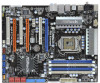
Motherboard Layout English 1 PS2_USB_PWR1 Jumper 22 Dr. Debug (LED) 2 ATX 12V Power Connector (ATX12V1) 23 USB 2.0 Header (USB8_9, Blue) 3 1156-Pin CPU Socket 24 Intel P55 Chipset 4 Chassis Fan Connector (CHA_FAN3) 25 Front Panel IEEE 1394 Header 5 2 x 240-pin DDR3 DIMM Slots (FRONT_1394, Red) (Dual Channel: DDR3_A2, DDR3_B2, Blue) 26 Chassis Fan ... Express 2.0 x16 Slot (PCIE1, Blue) 20 Infrared Module Header (IR1) 40 CPU Fan Connector (CPU_FAN1) 21 USB 2.0 Header (USB10_11, Blue) 41 Power Fan Connector (PWR_FAN1) 2 ASRock P55 Extreme Motherboard
Motherboard Layout English 1 PS2_USB_PWR1 Jumper 22 Dr. Debug (LED) 2 ATX 12V Power Connector (ATX12V1) 23 USB 2.0 Header (USB8_9, Blue) 3 1156-Pin CPU Socket 24 Intel P55 Chipset 4 Chassis Fan Connector (CHA_FAN3) 25 Front Panel IEEE 1394 Header 5 2 x 240-pin DDR3 DIMM Slots (FRONT_1394, Red) (Dual Channel: DDR3_A2, DDR3_B2, Blue) 26 Chassis Fan ... Express 2.0 x16 Slot (PCIE1, Blue) 20 Infrared Module Header (IR1) 40 CPU Fan Connector (CPU_FAN1) 21 USB 2.0 Header (USB10_11, Blue) 41 Power Fan Connector (PWR_FAN1) 2 ASRock P55 Extreme Motherboard

