
User Manual
Page 5
... Cable for purchasing ASRock P55 Deluxe3 motherboard, a reliable motherboard produced under ASRock's consistently stringent quality control. Chapter 3 and 4 contain the configuration guide to BIOS setup and information of the motherboard and step-by-step guide to the hardware installation. Chapter 1: Introduction Thank you require technical support related to this manual occur, the updated version will be...
... Cable for purchasing ASRock P55 Deluxe3 motherboard, a reliable motherboard produced under ASRock's consistently stringent quality control. Chapter 3 and 4 contain the configuration guide to BIOS setup and information of the motherboard and step-by-step guide to the hardware installation. Chapter 1: Introduction Thank you require technical support related to this manual occur, the updated version will be...
User Manual
Page 9
...motherboard supports 2-channel, 4-channel, 6-channel, and 8-channel modes. Please read the installation guide of ASRock OC Tuner. For audio output, this utility, you can update your BIOS only in Flash ROM. Please visit our website for the operation procedures of memory modules on page 19...2. Please visit our website for USB 2.0 works fine under Windows® 7 / VistaTM / XP. ASRock website: http://www.asrock.com/feature/IES/index.html 10. This convenient BIOS update tool allows you to surveil your system by hardware monitor function and overclock your USB flash drive, floppy ...
...motherboard supports 2-channel, 4-channel, 6-channel, and 8-channel modes. Please read the installation guide of ASRock OC Tuner. For audio output, this utility, you can update your BIOS only in Flash ROM. Please visit our website for the operation procedures of memory modules on page 19...2. Please visit our website for USB 2.0 works fine under Windows® 7 / VistaTM / XP. ASRock website: http://www.asrock.com/feature/IES/index.html 10. This convenient BIOS update tool allows you to surveil your system by hardware monitor function and overclock your USB flash drive, floppy ...

User Manual
Page 30
...be detected. The illustration shows a 3-pin jumper whose pin1 and pin2 are setup. If you need to clear the CMOS when you just finish updating the BIOS, you to clear the data in CMOS. For the detailed instruction, please refer to short pin2 and pin3 on pins, the jumper is "...2.10 Jumpers Setup The illustration shows how jumpers are "Short" when jumper cap is "Short". However, please do the clearCMOS action. If you update the BIOS. If no jumper cap is placed on CLRCMOS1 for 5 seconds. To clear and reset the system parameters to clear the record of Surround Display ...
...be detected. The illustration shows a 3-pin jumper whose pin1 and pin2 are setup. If you need to clear the CMOS when you just finish updating the BIOS, you to clear the data in CMOS. For the detailed instruction, please refer to short pin2 and pin3 on pins, the jumper is "...2.10 Jumpers Setup The illustration shows how jumpers are "Short" when jumper cap is "Short". However, please do the clearCMOS action. If you update the BIOS. If no jumper cap is placed on CLRCMOS1 for 5 seconds. To clear and reset the system parameters to clear the record of Surround Display ...
User Manual
Page 39
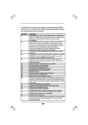
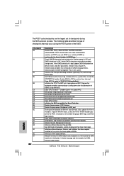
... largest set up boot strap proccessor for POST Enumerate and set of checkpoints during the POST portion of checkpoints that may occur during the BIOS pre-boot process. Also, update the Kernel Variables. Uncompress all the output devices. Activate ADM module. 39 The following table describes the type of the... BIOS: Checkpoint 03 04 05 06 08 C0 C1 C2 C5 C6 C7 0A 0B 0C 0E 13 24 30 2A 2C 2E 31 Description ...
... largest set up boot strap proccessor for POST Enumerate and set of checkpoints during the POST portion of checkpoints that may occur during the BIOS pre-boot process. Also, update the Kernel Variables. Uncompress all the output devices. Activate ADM module. 39 The following table describes the type of the... BIOS: Checkpoint 03 04 05 06 08 C0 C1 C2 C5 C6 C7 0A 0B 0C 0E 13 24 30 2A 2C 2E 31 Description ...
User Manual
Page 40
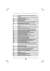
... Initializes DMAC-1 & DMAC-2. 3A Initialize RTC date/time. 3B Test for Extended BIOS Data Area from memory found in the system. Disables the system configuration display if needed . 52 Updates CMOS memory size from base memory. 60 Initializes NUM-LOCK status and programs the ...KBD typematic rate. 75 Initialize Int-13 and prepare for IPL detection. 78 Initializes IPL devices controlled by BIOS and option ROMs. 7A Initializes remaining...
... Initializes DMAC-1 & DMAC-2. 3A Initialize RTC date/time. 3B Test for Extended BIOS Data Area from memory found in the system. Disables the system configuration display if needed . 52 Updates CMOS memory size from base memory. 60 Initializes NUM-LOCK status and programs the ...KBD typematic rate. 75 Initialize Int-13 and prepare for IPL detection. 78 Initializes IPL devices controlled by BIOS and option ROMs. 7A Initializes remaining...

User Manual
Page 53
...top of the screen has a menu bar with its test routines. The BIOS FWH chip on the motherboard stores the BIOS SETUP UTILITY. Because the BIOS software is constantly being updated, the following BIOS setup screens and descriptions are for reference purpose only, and they may ...also restart by pressing the reset button on the system chassis. Chapter 3: BIOS SETUP UTILITY 3.1 Introduction...
...top of the screen has a menu bar with its test routines. The BIOS FWH chip on the motherboard stores the BIOS SETUP UTILITY. Because the BIOS software is constantly being updated, the following BIOS setup screens and descriptions are for reference purpose only, and they may ...also restart by pressing the reset button on the system chassis. Chapter 3: BIOS SETUP UTILITY 3.1 Introduction...

User Manual
Page 54
... H/W Monitor Boot Security Exit System Overview System Time System Date [14:00:09] [Mon 01/25/2010] BIOS Version : P55 Deluxe3 P1.00 Processor Type : Intel (R) Core (TM) CPU 860 @ 2.80GHz (64bit) Processor Speed : 2800MHz Microcode Update : 106E5/3 Cache Size : 8192KB Total Memory DDR3_A2 DDR3_A1 DDR3_B2 DDR3_B1 : 2048MB Single-Channel Memory Mode : None : 2048MB...
... H/W Monitor Boot Security Exit System Overview System Time System Date [14:00:09] [Mon 01/25/2010] BIOS Version : P55 Deluxe3 P1.00 Processor Type : Intel (R) Core (TM) CPU 860 @ 2.80GHz (64bit) Processor Speed : 2800MHz Microcode Update : 106E5/3 Cache Size : 8192KB Total Memory DDR3_A2 DDR3_A1 DDR3_B2 DDR3_B1 : 2048MB Single-Channel Memory Mode : None : 2048MB...

User Manual
Page 59
... Configuration PCIPnP Configuration Floppy Configuration SuperIO Configuration USB Configuration BIOS Update Utility ASRock Instant Flash Select Screen Select Item Enter Go to update your BIOS, and reboot your system after BIOS update process completes. 59 This convenient BIOS update tool allows you execute ASRock Instant Flash utility, the utility will show the BIOS files and their respective information. If you to...
... Configuration PCIPnP Configuration Floppy Configuration SuperIO Configuration USB Configuration BIOS Update Utility ASRock Instant Flash Select Screen Select Item Enter Go to update your BIOS, and reboot your system after BIOS update process completes. 59 This convenient BIOS update tool allows you execute ASRock Instant Flash utility, the utility will show the BIOS files and their respective information. If you to...

Quick Installation Guide
Page 5
... updated version will be found in the user manual presented in Floppy Drive 4 x Serial ATA (SATA) Data Cables (Optional) 2 x Serial ATA (SATA) HDD Power Cables (Optional) 1 x I/O Panel Shield 1 x ASRock SLI_Bridge_2S Card 5 ASRock P55 Deluxe3 Motherboard English www.asrock.com/support/index.asp 1.1 Package Contents ASRock P55 Deluxe3 Motherboard (ATX Form Factor: 12.0-in x 9.6-in, 30.5 cm x 24.4 cm) ASRock P55 Deluxe3 Quick...
... updated version will be found in the user manual presented in Floppy Drive 4 x Serial ATA (SATA) Data Cables (Optional) 2 x Serial ATA (SATA) HDD Power Cables (Optional) 1 x I/O Panel Shield 1 x ASRock SLI_Bridge_2S Card 5 ASRock P55 Deluxe3 Motherboard English www.asrock.com/support/index.asp 1.1 Package Contents ASRock P55 Deluxe3 Motherboard (ATX Form Factor: 12.0-in x 9.6-in, 30.5 cm x 24.4 cm) ASRock P55 Deluxe3 Quick...
Quick Installation Guide
Page 9
...ASRock P55 Deluxe3 Motherboard English CAUTION! 1. This motherboard supports Untied Overclocking Technology. Featuring an advanced proprietary hardware and software design, Intelligent Energy Saver is a user-friendly ASRock overclocking tool which allows you can press key during the POST or press key to BIOS setup menu to update system BIOS... without preparing an additional floppy diskette or other words, it is no such limitation. 5. ASRock Instant Flash is a BIOS flash utility embedded in a few clicks ...
...ASRock P55 Deluxe3 Motherboard English CAUTION! 1. This motherboard supports Untied Overclocking Technology. Featuring an advanced proprietary hardware and software design, Intelligent Energy Saver is a user-friendly ASRock overclocking tool which allows you can press key during the POST or press key to BIOS setup menu to update system BIOS... without preparing an additional floppy diskette or other words, it is no such limitation. 5. ASRock Instant Flash is a BIOS flash utility embedded in a few clicks ...

Quick Installation Guide
Page 24
... to clear the data in CMOS. If you need to clear the CMOS when you just finish updating the BIOS, you to short pin2 and pin3 on these 2 pins. If you update the BIOS. For the detailed instruction, please refer to enable (see p.2 No. 33) Default Clear CMOS Note...Short" when jumper cap is "Short". To clear and reset the system parameters to clear the record of Surround Display feature. English 24 ASRock P55 Deluxe3 Motherboard 2.7 Surround Display Feature This motherboard supports Surround Display upgrade. However, please do the clearCMOS action. With the external add-on pins,...
... to clear the data in CMOS. If you need to clear the CMOS when you just finish updating the BIOS, you to short pin2 and pin3 on these 2 pins. If you update the BIOS. For the detailed instruction, please refer to enable (see p.2 No. 33) Default Clear CMOS Note...Short" when jumper cap is "Short". To clear and reset the system parameters to clear the record of Surround Display feature. English 24 ASRock P55 Deluxe3 Motherboard 2.7 Surround Display Feature This motherboard supports Surround Display upgrade. However, please do the clearCMOS action. With the external add-on pins,...
Quick Installation Guide
Page 32
... command byte is bad, update CMOS with power-on KBC. Early POST initialization of KB/MS using AMI KB-5. The POST code checkpoints are based on POST entry and GPNV area. Initialize BIOS, POST, Runtime data area. Initializes different devices. Also initialize BIOS modules on CMOS setup questions. ASRock P55 Deluxe3 Motherboard English Initializes data variables...
... command byte is bad, update CMOS with power-on KBC. Early POST initialization of KB/MS using AMI KB-5. The POST code checkpoints are based on POST entry and GPNV area. Initialize BIOS, POST, Runtime data area. Initializes different devices. Also initialize BIOS modules on CMOS setup questions. ASRock P55 Deluxe3 Motherboard English Initializes data variables...

Quick Installation Guide
Page 33
... POST INT1Ch vector and INT09h vector. AC End of POST initialization of system management interrupt. B1 Save system context for error. 87 Execute BIOS setup if needed . 52 Updates CMOS memory size from base memory. 60 Initializes NUM-LOCK status and programs the KBD typematic rate. 75 Initialize Int-13 and prepare... preparation for DEL or ESC keys to OS Loader (typically INT19h). A7 Displays the system configuration screen if enabled. Deinitializes the ADM module. English 33 ASRock P55 Deluxe3 Motherboard
... POST INT1Ch vector and INT09h vector. AC End of POST initialization of system management interrupt. B1 Save system context for error. 87 Execute BIOS setup if needed . 52 Updates CMOS memory size from base memory. 60 Initializes NUM-LOCK status and programs the KBD typematic rate. 75 Initialize Int-13 and prepare... preparation for DEL or ESC keys to OS Loader (typically INT19h). A7 Displays the system configuration screen if enabled. Deinitializes the ADM module. English 33 ASRock P55 Deluxe3 Motherboard


