User Manual
Page 3
... 5 1.2 Specifications 6 1.3 Motherboard Layout 9 1.4 I/O Panel 10 2 Installation 11 2.1 Screw Holes 11 2.2 Pre-installation Precautions 11 2.3 CPU Installation 12 2.4 Installation of Heatsink and CPU fan 14 2.5 Installation of Memory Modules (DIMM 15 2.6 Expansion Slots (PCI and PCI Express Slots 16 2.7 Easy Multi Monitor Feature 17 2.8 Jumpers Setup 18 2.9 Onboard Headers and Connectors 19 2.10...
... 5 1.2 Specifications 6 1.3 Motherboard Layout 9 1.4 I/O Panel 10 2 Installation 11 2.1 Screw Holes 11 2.2 Pre-installation Precautions 11 2.3 CPU Installation 12 2.4 Installation of Heatsink and CPU fan 14 2.5 Installation of Memory Modules (DIMM 15 2.6 Expansion Slots (PCI and PCI Express Slots 16 2.7 Easy Multi Monitor Feature 17 2.8 Jumpers Setup 18 2.9 Onboard Headers and Connectors 19 2.10...

User Manual
Page 7
... affect your system stability, or even cause damage to the components and devices of your own risk and expense. Front panel audio connector - 3 x USB 2.0 headers (support 6 USB 2.0 ports) (see CAUTION 8) - Chassis Temperature Sensing - ASRock U-COP (see CAUTION 9) - CPU Frequency Stepless Control (see CAUTION 10) - CPU Quiet Fan - CD in the BIOS, applying Untied...
... affect your system stability, or even cause damage to the components and devices of your own risk and expense. Front panel audio connector - 3 x USB 2.0 headers (support 6 USB 2.0 ports) (see CAUTION 8) - Chassis Temperature Sensing - ASRock U-COP (see CAUTION 9) - CPU Frequency Stepless Control (see CAUTION 10) - CPU Quiet Fan - CD in the BIOS, applying Untied...

User Manual
Page 9
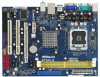
... 4 CPU Fan Connector (CPU_FAN1) 17 Floppy Connector (FLOPPY1) 5 2 x 240-pin DDR2 DIMM Slots 18 Front Panel Audio Header (DDRII_1, DDRII_2; Red) 25 USB 2.0 Header (USB6_7, Blue) 13 Secondary SATAII Connector (SATAII_2; Red) 21 PCI Express x16 Slot (PCIE2) 9 Chassis Fan ...Jumper (CLRCMOS1) 23 BIOS SPI Chip 11 Third SATAII Connector (SATAII_3; Red) 26 USB 2.0 Header (USB4_5, Blue) 14 System Panel Header (PANEL1, Orange) 27 ATX 12V Connector (ATX12V1) 9 Red) 24 USB 2.0 Header (USB8_9, Blue) 12 Fourth SATAII Connector (SATAII_4; Yellow) (HD_AUDIO1, Lime) 6 ATX Power...
... 4 CPU Fan Connector (CPU_FAN1) 17 Floppy Connector (FLOPPY1) 5 2 x 240-pin DDR2 DIMM Slots 18 Front Panel Audio Header (DDRII_1, DDRII_2; Red) 25 USB 2.0 Header (USB6_7, Blue) 13 Secondary SATAII Connector (SATAII_2; Red) 21 PCI Express x16 Slot (PCIE2) 9 Chassis Fan ...Jumper (CLRCMOS1) 23 BIOS SPI Chip 11 Third SATAII Connector (SATAII_3; Red) 26 USB 2.0 Header (USB4_5, Blue) 14 System Panel Header (PANEL1, Orange) 27 ATX 12V Connector (ATX12V1) 9 Red) 24 USB 2.0 Header (USB8_9, Blue) 12 Fourth SATAII Connector (SATAII_4; Yellow) (HD_AUDIO1, Lime) 6 ATX Power...

User Manual
Page 10
... and rear output devices playbacks two different audio streams simultaneously", and click "ok". Please select "Mixer ToolBox" , click "Enable playback multi-streaming", and click "ok". 1 . 4 I/O Panel 1 2 3 4 5 6 10 9 8 7 1 PS/2 Mouse Port (Green) 2 USB 2.0 Ports (USB23) 3 RJ-45 Port 4 Line In (Light Blue) 5 Line Out (... COM Port 10 PS/2 Keyboard Port (Purple) * To enable Multi-Streaming function, you need to connect a front panel audio cable to use front panel audio. Then reboot your computer, you are allowed to select "Realtek HDA Primary output" to use Rear Speaker and Front...
... and rear output devices playbacks two different audio streams simultaneously", and click "ok". Please select "Mixer ToolBox" , click "Enable playback multi-streaming", and click "ok". 1 . 4 I/O Panel 1 2 3 4 5 6 10 9 8 7 1 PS/2 Mouse Port (Green) 2 USB 2.0 Ports (USB23) 3 RJ-45 Port 4 Line In (Light Blue) 5 Line Out (... COM Port 10 PS/2 Keyboard Port (Purple) * To enable Multi-Streaming function, you need to connect a front panel audio cable to use front panel audio. Then reboot your computer, you are allowed to select "Realtek HDA Primary output" to use Rear Speaker and Front...

User Manual
Page 20
... it to receive stereo audio input from sound sources such as below: 20 If you to the front panel audio header as a CD-ROM, DVD-ROM, TV tuner card, or MPEG card. Print Port Header (25-pin LPT1) (see p.9 No. 16) AFD# ERROR# PINIT# SLIN# GND 1 SPD7 ... p.9 No. 19) CD1 CD-L GND GND CD-R This is an interface for print port cable that allows convenient connection and control of printer devices. Front Panel Audio Header (9-pin HD_AUDIO1) (see p.9 No. 24) USB_PWR P-5 P+5 GND DUMMY 1 GND P+4 P-4 USB_PWR USB_PWR P-7 P+7 GND DUMMY 1 GND P+6 P-6 USB_PWR USB_PWR P-9 P+9 GND DUMMY 1 GND P+8...
... it to receive stereo audio input from sound sources such as below: 20 If you to the front panel audio header as a CD-ROM, DVD-ROM, TV tuner card, or MPEG card. Print Port Header (25-pin LPT1) (see p.9 No. 16) AFD# ERROR# PINIT# SLIN# GND 1 SPD7 ... p.9 No. 19) CD1 CD-L GND GND CD-R This is an interface for print port cable that allows convenient connection and control of printer devices. Front Panel Audio Header (9-pin HD_AUDIO1) (see p.9 No. 24) USB_PWR P-5 P+5 GND DUMMY 1 GND P+4 P-4 USB_PWR USB_PWR P-7 P+7 GND DUMMY 1 GND P+6 P-6 USB_PWR USB_PWR P-9 P+9 GND DUMMY 1 GND P+8...

User Manual
Page 21
... [Enabled]. Enter BIOS Setup Utility. Please connect the chassis speaker to this connector and match the black wire to this header. System Panel Header (9-pin PANEL1) (see p.9 No. 14) Chassis Speaker Header (4-pin SPEAKER 1) (see p.9 No. 15) Chassis Fan Connector (3-pin CHA_FAN1) (see p.9 No. 4) GND 1...(see p.9 No. 9) PLED+ PLEDPWRBTN# GND 1 DUMMY RESET# GND HDLEDHDLED+ 1 SPEAKER DUMMY DUMMY +5V GND +12V CHA_FAN_SPEED This header accommodates several system front panel functions. If you plan to connect the 3-Pin CPU fan to the CPU fan connector on the lower right hand taskbar to Pin...
... [Enabled]. Enter BIOS Setup Utility. Please connect the chassis speaker to this connector and match the black wire to this header. System Panel Header (9-pin PANEL1) (see p.9 No. 14) Chassis Speaker Header (4-pin SPEAKER 1) (see p.9 No. 15) Chassis Fan Connector (3-pin CHA_FAN1) (see p.9 No. 4) GND 1...(see p.9 No. 9) PLED+ PLEDPWRBTN# GND 1 DUMMY RESET# GND HDLEDHDLED+ 1 SPEAKER DUMMY DUMMY +5V GND +12V CHA_FAN_SPEED This header accommodates several system front panel functions. If you plan to connect the 3-Pin CPU fan to the CPU fan connector on the lower right hand taskbar to Pin...

Quick Installation Guide
Page 2
...Purple) 3 NVIDIA GeForce 7100 / nForce 630i Chipset 16 Print Port Header (LPT1, Purple) 4 CPU Fan Connector (CPU_FAN1) 17 Floppy Connector (FLOPPY1) 5 2 x 240-pin DDR2 DIMM Slots 18 Front Panel Audio Header (DDRII_1, DDRII_2; Red) 21 PCI Express x16 Slot (PCIE2) ...Jumper (CLRCMOS1) 23 BIOS SPI Chip 11 Third SATAII Connector (SATAII_3; Red) 26 USB 2.0 Header (USB4_5, Blue) 14 System Panel Header (PANEL1, Orange) 27 ATX 12V Connector (ATX12V1) 2 ASRock N73PV-GS / N73PV-S Motherboard Yellow) (HD_AUDIO1, Lime) 6 ATX Power Connector (ATXPWR1) 19 Internal Audio Connector: CD1...
...Purple) 3 NVIDIA GeForce 7100 / nForce 630i Chipset 16 Print Port Header (LPT1, Purple) 4 CPU Fan Connector (CPU_FAN1) 17 Floppy Connector (FLOPPY1) 5 2 x 240-pin DDR2 DIMM Slots 18 Front Panel Audio Header (DDRII_1, DDRII_2; Red) 21 PCI Express x16 Slot (PCIE2) ...Jumper (CLRCMOS1) 23 BIOS SPI Chip 11 Third SATAII Connector (SATAII_3; Red) 26 USB 2.0 Header (USB4_5, Blue) 14 System Panel Header (PANEL1, Orange) 27 ATX 12V Connector (ATX12V1) 2 ASRock N73PV-GS / N73PV-S Motherboard Yellow) (HD_AUDIO1, Lime) 6 ATX Power Connector (ATXPWR1) 19 Internal Audio Connector: CD1...

Quick Installation Guide
Page 3
...panel audio header. For Windows® VistaTM: After restarting your system. Set "Speaker Configuration" to below steps for the software setting of Multi-Streaming. Please refer to "Quadraphonic" or "Stereo". Then reboot your computer, please double-click "Realtek HD Audio Manager" on your system. 3 ASRock N73PV-GS / N73PV...-S Motherboard English Click "Device advanced settings", choose "Make front and rear output devices playbacks two different audio streams simultaneously", and click "ok". I/O Panel 1 PS/2 Mouse Port (Green...
...panel audio header. For Windows® VistaTM: After restarting your system. Set "Speaker Configuration" to below steps for the software setting of Multi-Streaming. Please refer to "Quadraphonic" or "Stereo". Then reboot your computer, please double-click "Realtek HD Audio Manager" on your system. 3 ASRock N73PV-GS / N73PV...-S Motherboard English Click "Device advanced settings", choose "Make front and rear output devices playbacks two different audio streams simultaneously", and click "ok". I/O Panel 1 PS/2 Mouse Port (Green...

Quick Installation Guide
Page 6
- 1 x Print port header - CD in the BIOS, applying Untied Overclocking Technology, or using the thirdparty overclocking tools. CPU Frequency Stepless Control (see CAUTION 10) - ASRock U-COP (see CAUTION 9) - Supports "Plug and Play" - Supports Smart BIOS Support CD - Chassis Fan Tachometer - CPU Quiet Fan - It should be done at your system. English 6 ASRock N73PV-GS / N73PV-S Motherboard...
- 1 x Print port header - CD in the BIOS, applying Untied Overclocking Technology, or using the thirdparty overclocking tools. CPU Frequency Stepless Control (see CAUTION 10) - ASRock U-COP (see CAUTION 9) - Supports "Plug and Play" - Supports Smart BIOS Support CD - Chassis Fan Tachometer - CPU Quiet Fan - It should be done at your system. English 6 ASRock N73PV-GS / N73PV-S Motherboard...

Quick Installation Guide
Page 16
...to the front panel audio header as a CD-ROM, DVD-ROM, TV tuner card, or MPEG card. This connector allows you use AC'97 audio panel, please install it to receive stereo audio input from sound sources such as below: 16 ASRock N73PV-GS / N73PV-S Motherboard English High... Definition Audio supports Jack Sensing, but the panel wire on this motherboard. USB 2.0 Headers (9-pin US4_5) (see p.2 No. 26) (9-pin USB6_7) (see p.2 No. 25) (9-pin USB8_9) (...
...to the front panel audio header as a CD-ROM, DVD-ROM, TV tuner card, or MPEG card. This connector allows you use AC'97 audio panel, please install it to receive stereo audio input from sound sources such as below: 16 ASRock N73PV-GS / N73PV-S Motherboard English High... Definition Audio supports Jack Sensing, but the panel wire on this motherboard. USB 2.0 Headers (9-pin US4_5) (see p.2 No. 26) (9-pin USB6_7) (see p.2 No. 25) (9-pin USB8_9) (...

Quick Installation Guide
Page 17
...bit OS: Click the right-top "Folder" icon , choose "Disable front panel jack detection", and save the change by clicking "OK". Enter Windows system. Pin 1-3 Connected 3-Pin Fan Installation 17 ASRock N73PV-GS / N73PV-S Motherboard Connect Ground (GND) to OUT2_L. If you plan to connect the... 3-Pin CPU fan to the CPU fan connector on the lower right hand taskbar to MIC2_L. Connect Audio_R (RIN) to OUT2_R and Audio_L (LIN) to Ground (GND). System Panel Header (9-pin...
...bit OS: Click the right-top "Folder" icon , choose "Disable front panel jack detection", and save the change by clicking "OK". Enter Windows system. Pin 1-3 Connected 3-Pin Fan Installation 17 ASRock N73PV-GS / N73PV-S Motherboard Connect Ground (GND) to OUT2_L. If you plan to connect the... 3-Pin CPU fan to the CPU fan connector on the lower right hand taskbar to MIC2_L. Connect Audio_R (RIN) to OUT2_R and Audio_L (LIN) to Ground (GND). System Panel Header (9-pin...


