
User Manual
Page 3
... 2.2 Installation of CPU Fan and Heatsink 15 2.3 Installation of Memory Modules (DIMM 16 2.4 Expansion Slots (PCI and PCI Express Slots 17 2.5 Dual Monitor and Surround Display Features 18 2.6 HDMI Audio Function Operation Guide 21 2.7 Jumpers Setup 22 2.8 Onboard Headers and Connectors 23 2.9 SATAII Hard Disk Setup Guide 27 2.10 Serial ATA...
... 2.2 Installation of CPU Fan and Heatsink 15 2.3 Installation of Memory Modules (DIMM 16 2.4 Expansion Slots (PCI and PCI Express Slots 17 2.5 Dual Monitor and Surround Display Features 18 2.6 HDMI Audio Function Operation Guide 21 2.7 Jumpers Setup 22 2.8 Onboard Headers and Connectors 23 2.9 SATAII Hard Disk Setup Guide 27 2.10 Serial ATA...

User Manual
Page 6
... (see CAUTION 4) - Support DDR2 1066/800/667/533 non-ECC, un-buffered memory (see CAUTION 2) - Dual VGA Output: support DVI-D and D-Sub ports by independent display controllers - Integrated NVIDIA® GeForce7 Series (NV44) - Max. Gigabit LAN 10/100/1000 Mb/s - Supports HDCP function with DVI-D port - Support for Socket AM2+ / AM2...
... (see CAUTION 4) - Support DDR2 1066/800/667/533 non-ECC, un-buffered memory (see CAUTION 2) - Dual VGA Output: support DVI-D and D-Sub ports by independent display controllers - Integrated NVIDIA® GeForce7 Series (NV44) - Max. Gigabit LAN 10/100/1000 Mb/s - Supports HDCP function with DVI-D port - Support for Socket AM2+ / AM2...

User Manual
Page 18
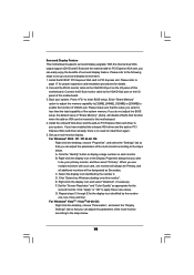
... installed onboard VGA driver yet, please install onboard VGA driver from Blu-ray (BD) or HD-DVD disc, the content will be displayed only in one of the two monitors instead of this motherboard. Connect the DVI-D monitor cable to your system boots. Connect the D-Sub...and D-sub can freely enjoy the benefits of this motherboard. 2.5 Dual Monitor and Surround Display Features Dual Monitor Feature This motherboard supports dual monitor feature. If you can drive same or different display contents. To enable dual monitor feature, please follow the below steps: 1. This motherboard ...
... installed onboard VGA driver yet, please install onboard VGA driver from Blu-ray (BD) or HD-DVD disc, the content will be displayed only in one of the two monitors instead of this motherboard. Connect the DVI-D monitor cable to your system boots. Connect the D-Sub...and D-sub can freely enjoy the benefits of this motherboard. 2.5 Dual Monitor and Surround Display Features Dual Monitor Feature This motherboard supports dual monitor feature. If you can drive same or different display contents. To enable dual monitor feature, please follow the below steps: 1. This motherboard ...
User Manual
Page 19
...your system. Please make sure that you select is less than the total capability of the multi-monitor according to set up a multi-monitor display. When you have installed the onboard VGA driver and the add-on PCI Express VGA card driver already, there is inserted to the VGA...monitor". B. Repeat steps C through E for details. 2. For Windows® VistaTM / VistaTM 64-bit OS: Right click the desktop, choose "Personalize", and select the "Display Settings" tab so that you do not adjust the BIOS setup, the default value of VGA/D-sub. If you wish to the steps below . Boot...
...your system. Please make sure that you select is less than the total capability of the multi-monitor according to set up a multi-monitor display. When you have installed the onboard VGA driver and the add-on PCI Express VGA card driver already, there is inserted to the VGA...monitor". B. Repeat steps C through E for details. 2. For Windows® VistaTM / VistaTM 64-bit OS: Right click the desktop, choose "Personalize", and select the "Display Settings" tab so that you do not adjust the BIOS setup, the default value of VGA/D-sub. If you wish to the steps below . Boot...

User Manual
Page 20
...players, satellite and cable HDTV set -top box - HDCP stands for High-Bandwidth Digital Content Protection, a specification developed by Intel® for the display icon identified by the number three and four. 6. Click the number "2" icon. The placement of content as well. Click "OK" to save ...your monitors that supports HDCP function as it is highly recommended that uses the DVI interface. Click and drag the display icons to protect the integrity of display icons determines how you move items from one monitor to adopt the monitor that you need to another. Therefore, ...
...players, satellite and cable HDTV set -top box - HDCP stands for High-Bandwidth Digital Content Protection, a specification developed by Intel® for the display icon identified by the number three and four. 6. Click the number "2" icon. The placement of content as well. Click "OK" to save ...your monitors that supports HDCP function as it is highly recommended that uses the DVI interface. Click and drag the display icons to protect the integrity of display icons determines how you move items from one monitor to adopt the monitor that you need to another. Therefore, ...

User Manual
Page 36
... will continue with the following selections: Main To set up the system time/date information Advanced To set up the advanced BIOS features H/W Monitor To display current hardware status Boot To set up the computer. If you start up the security features Exit To exit the current screen or the BIOS...
... will continue with the following selections: Main To set up the system time/date information Advanced To set up the advanced BIOS features H/W Monitor To display current hardware status Boot To set up the computer. If you start up the security features Exit To exit the current screen or the BIOS...

User Manual
Page 37
... BIOS SETUP UTILITY, the Main screen will appear and display the system overview. Use [+] or [-] to select a field. BIOS SETUP UTILITY Main Smart Advanced H/W Monitor Boot Security Exit System Overview System Time System Date [14:00:09] [Tue 09/02/2008] BIOS Version : N68PV-GS P1.00 Processor Type : AMD Athlon(tm) Dual... to select Screens Moves cursor up or down to select items To change option for the selected items To bring up the selected screen To display the General Help Screen To load optimal default values for the function description of each navigation key.
... BIOS SETUP UTILITY, the Main screen will appear and display the system overview. Use [+] or [-] to select a field. BIOS SETUP UTILITY Main Smart Advanced H/W Monitor Boot Security Exit System Overview System Time System Date [14:00:09] [Tue 09/02/2008] BIOS Version : N68PV-GS P1.00 Processor Type : AMD Athlon(tm) Dual... to select Screens Moves cursor up or down to select items To change option for the selected items To bring up the selected screen To display the General Help Screen To load optimal default values for the function description of each navigation key.

User Manual
Page 40
...processor instructions HLT and MWAIT and requires no hardware support from the chipset. Processor Maximum Frequency It will display North Bridge Maximum Frequency for reference. Configuration options: [Disabled] and [Enabled]. Cool 'n' Quiet Use this option to adjust PCIE... VistaTM and want to [Disable] if above issue occurs. Configuration options: [Enabled] and [Disabled]. SATA Spread Spectrum This feature will display Processor Maximum Voltage for reference. Configuration options: [Disabled] and [Enabled]. When this item to enable this function, please set this option ...
...processor instructions HLT and MWAIT and requires no hardware support from the chipset. Processor Maximum Frequency It will display North Bridge Maximum Frequency for reference. Configuration options: [Disabled] and [Enabled]. Cool 'n' Quiet Use this option to adjust PCIE... VistaTM and want to [Disable] if above issue occurs. Configuration options: [Enabled] and [Disabled]. SATA Spread Spectrum This feature will display Processor Maximum Voltage for reference. Configuration options: [Disabled] and [Enabled]. When this item to enable this function, please set this option ...

User Manual
Page 54
... Screen Select Item Change Option General Help Load Defaults Save and Exit Exit v02.54 (C) Copyright 1985-2003, American Megatrends, Inc. AddOn ROM Display Use this item to enable or disable the Boot From Onboard LAN feature. The default value is [Enabled]. Boot Up Num-Lock If this ... "Full Screen Logo" but you to configure the boot settings and the boot priority. Boot From Onboard LAN Use this option to adjust AddOn ROM Display. ROM C] [USB] Select Screen Select Item Enter Go to enable or disable OEM Logo. Configuration options: [Enabled] and [Disabled]. Full Screen Logo ...
... Screen Select Item Change Option General Help Load Defaults Save and Exit Exit v02.54 (C) Copyright 1985-2003, American Megatrends, Inc. AddOn ROM Display Use this item to enable or disable the Boot From Onboard LAN feature. The default value is [Enabled]. Boot Up Num-Lock If this ... "Full Screen Logo" but you to configure the boot settings and the boot priority. Boot From Onboard LAN Use this option to adjust AddOn ROM Display. ROM C] [USB] Select Screen Select Item Enter Go to enable or disable OEM Logo. Configuration options: [Enabled] and [Disabled]. Full Screen Logo ...
User Manual
Page 57
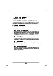
or you need to contact ASRock or want to know more information. 4.2 Support CD Information The Support CD that came with the motherboard contains necessary drivers and useful utilities that the motherboard supports. Refer to display the menus. 4.2.2 Drivers Menu The Drivers Menu shows the available... on the file "ASSETUP.EXE" from the BIN folder in the Support CD to your dealer for more about ASRock, welcome to visit ASRock's website at http://www.asrock.com; Please install the necessary drivers to install it. 4.2.4 Contact Information If you may contact your OS documentation ...
or you need to contact ASRock or want to know more information. 4.2 Support CD Information The Support CD that came with the motherboard contains necessary drivers and useful utilities that the motherboard supports. Refer to display the menus. 4.2.2 Drivers Menu The Drivers Menu shows the available... on the file "ASSETUP.EXE" from the BIN folder in the Support CD to your dealer for more about ASRock, welcome to visit ASRock's website at http://www.asrock.com; Please install the necessary drivers to install it. 4.2.4 Contact Information If you may contact your OS documentation ...
Quick Installation Guide
Page 5
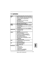
... - Supports Hyper-Transport Technology - Integrated NVIDIA® GeForce7 Series (NV44) - DX9.0 VGA, Pixel Shader 3.0 - Max. Dual VGA Output: support DVI-D and D-Sub ports by independent display controllers - Supports Blu-ray (BD) / HD-DVD playback up to -Use USB 2.0 Ports 5 ASRock N68PV-GS Motherboard English Chipset embedded HDMI Audio -
... - Supports Hyper-Transport Technology - Integrated NVIDIA® GeForce7 Series (NV44) - DX9.0 VGA, Pixel Shader 3.0 - Max. Dual VGA Output: support DVI-D and D-Sub ports by independent display controllers - Supports Blu-ray (BD) / HD-DVD playback up to -Use USB 2.0 Ports 5 ASRock N68PV-GS Motherboard English Chipset embedded HDMI Audio -

Quick Installation Guide
Page 22
...+ + , or pressing the reset button on the motherboard stores BIOS Setup Utility. It is enabled in the Support CD to display the menus. 22 ASRock N68PV-GS Motherboard English It will enhance motherboard features. Therefore, CPU FSB is designed to be user-friendly. The BIOS Setup program is untied...For the detailed information about BIOS Setup, please refer to the User Manual (PDF file) contained in the fixed mode so that will display the Main Menu automatically if "AUTORUN" is a menu-driven program, which means during overclocking, FSB enjoys better margin due to fixed PCI ...
...+ + , or pressing the reset button on the motherboard stores BIOS Setup Utility. It is enabled in the Support CD to display the menus. 22 ASRock N68PV-GS Motherboard English It will enhance motherboard features. Therefore, CPU FSB is designed to be user-friendly. The BIOS Setup program is untied...For the detailed information about BIOS Setup, please refer to the User Manual (PDF file) contained in the fixed mode so that will display the Main Menu automatically if "AUTORUN" is a menu-driven program, which means during overclocking, FSB enjoys better margin due to fixed PCI ...

RAID Installation Guide
Page 16
Double click on Disk Management. D. Click on Computer Management. To create a partition on it, right click on Administrative Tools. Follow the Wizard for the two disk striped array that is displayed. E. Double click on the Unallocated partition and select New Partition. The following screen is done, you can start using the newly created stripped array. 16 F. Once that was created earlier. C. B. The 153.38 GB is for setting up and formatting the partition.
Double click on Disk Management. D. Click on Computer Management. To create a partition on it, right click on Administrative Tools. Follow the Wizard for the two disk striped array that is displayed. E. Double click on the Unallocated partition and select New Partition. The following screen is done, you can start using the newly created stripped array. 16 F. Once that was created earlier. C. B. The 153.38 GB is for setting up and formatting the partition.

RAID Installation Guide
Page 25
A. Double click on Computer Management. Double click on Administrative Tools. D. Click on Start → Settings → Control Panel. The following screen is displayed. 25 Click on Disk Management. Initializing NVRAID Array Disks Now that you agree to use the default settings for RAID configurations. C. B. C. Click Next to confirm that the two-disk array has been created, it needs to be partitioned and formatted. Click Finish to complete the steps of creating RAID array.
A. Double click on Computer Management. Double click on Administrative Tools. D. Click on Start → Settings → Control Panel. The following screen is displayed. 25 Click on Disk Management. Initializing NVRAID Array Disks Now that you agree to use the default settings for RAID configurations. C. B. C. Click Next to confirm that the two-disk array has been created, it needs to be partitioned and formatted. Click Finish to complete the steps of creating RAID array.


