
User Manual
Page 4
... 36 3.1 Introduction 36 3.1.1 BIOS Menu Bar 36 3.1.2 Navigation Keys 37 3.2 Main Screen 37 3.3 Smart Screen 38 3.4 Advanced Screen 39 3.4.1 CPU Configuration 39 3.4.2 Chipset Configuration 44 3.4.3 ACPI Configuration 46 3.4.4 IDE ...
... 36 3.1 Introduction 36 3.1.1 BIOS Menu Bar 36 3.1.2 Navigation Keys 37 3.2 Main Screen 37 3.3 Smart Screen 38 3.4 Advanced Screen 39 3.4.1 CPU Configuration 39 3.4.2 Chipset Configuration 44 3.4.3 ACPI Configuration 46 3.4.4 IDE ...
User Manual
Page 5
... I/O Panel Shield 5 In this motherboard, please visit our website for purchasing ASRock N68PV-GS motherboard, a reliable motherboard produced under ASRock's consistently stringent quality control. Introduction Thank you require technical support related to quality and endurance. Chapter 3 and 4 contain the configuration guide to BIOS setup and information of the motherboard and step-by-step guide to...
... I/O Panel Shield 5 In this motherboard, please visit our website for purchasing ASRock N68PV-GS motherboard, a reliable motherboard produced under ASRock's consistently stringent quality control. Introduction Thank you require technical support related to quality and endurance. Chapter 3 and 4 contain the configuration guide to BIOS setup and information of the motherboard and step-by-step guide to...
User Manual
Page 7
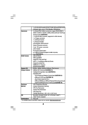
... "Plug and Play" - Drivers, Utilities, AntiVirus Software (Trial Version) Unique Feature - CPU Fan Tachometer - SMBIOS 2.3.1 Support - Supports Smart BIOS Support CD - ASRock OC Tuner (see CAUTION 12) - Chassis Fan Tachometer - - 1 x RJ-45 LAN Port with LED (ACT/LINK LED and SPEED LED... - FCC, CE * For detailed product information, please visit our website: http://www.asrock.com 7 HD Audio Jack: Line in header - ASRock U-COP (see CAUTION 10) BIOS Feature - 4Mb AMI BIOS - CPU/Chassis FAN connector - 24 pin ATX power connector - 4 pin 12V power...
... "Plug and Play" - Drivers, Utilities, AntiVirus Software (Trial Version) Unique Feature - CPU Fan Tachometer - SMBIOS 2.3.1 Support - Supports Smart BIOS Support CD - ASRock OC Tuner (see CAUTION 12) - Chassis Fan Tachometer - - 1 x RJ-45 LAN Port with LED (ACT/LINK LED and SPEED LED... - FCC, CE * For detailed product information, please visit our website: http://www.asrock.com 7 HD Audio Jack: Line in header - ASRock U-COP (see CAUTION 10) BIOS Feature - 4Mb AMI BIOS - CPU/Chassis FAN connector - 24 pin ATX power connector - 4 pin 12V power...
User Manual
Page 8
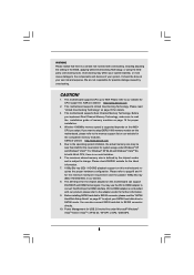
...4. Before you want to adopt DDR2 1066 memory module on this motherboard requires the proper hardware configuration. ASRock website http://www.asrock.com 5. ASRock website http://www.asrock.com 2. DVI to HDMI adapter is not bundled with our product, please refer to HDMI interface. You... for the reservation for the minimum hardware requirement and the passed 1080p Blu-ray (BD) / HD-DVD films in the BIOS, applying Untied Overclocking Technology, or using the thirdparty overclocking tools. This motherboard supports Untied Overclocking Technology. Please refer to our website...
...4. Before you want to adopt DDR2 1066 memory module on this motherboard requires the proper hardware configuration. ASRock website http://www.asrock.com 5. ASRock website http://www.asrock.com 2. DVI to HDMI adapter is not bundled with our product, please refer to HDMI interface. You... for the reservation for the minimum hardware requirement and the passed 1080p Blu-ray (BD) / HD-DVD films in the BIOS, applying Untied Overclocking Technology, or using the thirdparty overclocking tools. This motherboard supports Untied Overclocking Technology. Please refer to our website...

User Manual
Page 9
...Saver function, please enable Cool 'n' Quiet option in the BIOS setup in the BIOS setup, the memory performance will automatically shutdown. Before you install the PC system. 15. While CPU overheat is a user-friendly ASRock overclocking tool which allows you adopt. If you enable this... functions properly and unplug the power cord, then plug it is a revolutionary technology that delivers unparalleled power savings. ASRock website: http://www.asrock.com 13. Please visit our website for the operation procedures of Intelligent Energy Saver. Enabling this function for all CPU...
...Saver function, please enable Cool 'n' Quiet option in the BIOS setup in the BIOS setup, the memory performance will automatically shutdown. Before you install the PC system. 15. While CPU overheat is a user-friendly ASRock overclocking tool which allows you adopt. If you enable this... functions properly and unplug the power cord, then plug it is a revolutionary technology that delivers unparalleled power savings. ASRock website: http://www.asrock.com 13. Please visit our website for the operation procedures of Intelligent Energy Saver. Enabling this function for all CPU...

User Manual
Page 12
...: FRONT Bottom: MIC IN LAN PHY SATAII_1 (PORT 0) SATAII_2 (PORT 1) SATAII_3 (PORT 2) SATAII_4 (PORT 3) PCIE1 NVIDIA GeForce 7050 / nForce 630A MCP IDE1 PCIE2 N68PV-GS PCI1 RoHS RAID 4Mb BIOS CMOS BATTERY AUDIO CODEC CD1 1 HD_AUDIO1 FLOPPY1 20 19 PCI2 1 COM1 PANEL 1 PLED PWRBTN 1 HDLED RESET 1 USB4_5 1 USB6_7 CHA_FAN1 CLRCMOS1 1 SPEAKER1 1 18 17...
...: FRONT Bottom: MIC IN LAN PHY SATAII_1 (PORT 0) SATAII_2 (PORT 1) SATAII_3 (PORT 2) SATAII_4 (PORT 3) PCIE1 NVIDIA GeForce 7050 / nForce 630A MCP IDE1 PCIE2 N68PV-GS PCI1 RoHS RAID 4Mb BIOS CMOS BATTERY AUDIO CODEC CD1 1 HD_AUDIO1 FLOPPY1 20 19 PCI2 1 COM1 PANEL 1 PLED PWRBTN 1 HDLED RESET 1 USB4_5 1 USB6_7 CHA_FAN1 CLRCMOS1 1 SPEAKER1 1 18 17...
User Manual
Page 19
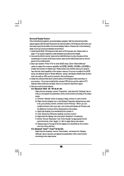
... internal dual VGA output support (DVI-D and D-Sub) and the external add-on each monitor. Install the NVIDIA® PCI Express VGA card to enter BIOS setup. Set up a surround display environment: 1. For Windows® 2000 / XP / XP 64-bit OS: Right click the desktop, choose "Properties", and select ...the "Settings" tab so that the value you do not adjust the BIOS setup, the default value of "Share Memory", [Auto], will be your card, one , two, three and four. C. Select the display icon identified by the...
... internal dual VGA output support (DVI-D and D-Sub) and the external add-on each monitor. Install the NVIDIA® PCI Express VGA card to enter BIOS setup. Set up a surround display environment: 1. For Windows® 2000 / XP / XP 64-bit OS: Right click the desktop, choose "Properties", and select ...the "Settings" tab so that the value you do not adjust the BIOS setup, the default value of "Share Memory", [Auto], will be your card, one , two, three and four. C. Select the display icon identified by the...
User Manual
Page 21
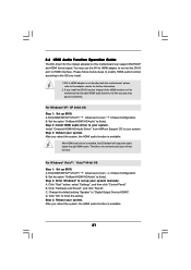
...to HDMI adapter is installed, the OS default will not function. For Windows® XP / XP 64-bit OS Step 1: Set up BIOS. B. Step 2: Install HDMI audio driver to the OS you install the DVI-D monitor instead of the HDMI monitor on this motherboard can support... adopted on this motherboard, please refer to HDMI interface. For Windows® VistaTM / VistaTM 64-bit OS Step 1: Set up BIOS. A. D. Install "Onboard HDMI HD Audio Driver" from ASRock Support CD to "Digital Output Device (HDMI)". 2.6 HDMI Audio Function Operation Guide The DVI-D port for further information. 2. If ...
...to HDMI adapter is installed, the OS default will not function. For Windows® XP / XP 64-bit OS Step 1: Set up BIOS. B. Step 2: Install HDMI audio driver to the OS you install the DVI-D monitor instead of the HDMI monitor on this motherboard can support... adopted on this motherboard, please refer to HDMI interface. For Windows® VistaTM / VistaTM 64-bit OS Step 1: Set up BIOS. A. D. Install "Onboard HDMI HD Audio Driver" from ASRock Support CD to "Digital Output Device (HDMI)". 2.6 HDMI Audio Function Operation Guide The DVI-D port for further information. 2. If ...

User Manual
Page 22
...Jumper Setting PS2_USB_PW1 1_2 2_3 Short pin2, pin3 to enable (see p.12, No. 14) 1_2 2_3 Default Clear CMOS Note: CLRCMOS1 allows you update the BIOS. To clear and reset the system parameters to short pin2 and pin3 on these 2 pins. When the jumper cap is placed on pins, the jumper ..., time, and system setup parameters. However, please do not clear the CMOS right after you to clear the CMOS when you just finish updating the BIOS, you do the clear-CMOS action. 22 Clear CMOS Jumper (CLRCMOS1) (see p.12, No. 1) +5V +5VSB +5VSB (standby) for 15 seconds, use a jumper cap ...
...Jumper Setting PS2_USB_PW1 1_2 2_3 Short pin2, pin3 to enable (see p.12, No. 14) 1_2 2_3 Default Clear CMOS Note: CLRCMOS1 allows you update the BIOS. To clear and reset the system parameters to short pin2 and pin3 on these 2 pins. When the jumper cap is placed on pins, the jumper ..., time, and system setup parameters. However, please do not clear the CMOS right after you to clear the CMOS when you just finish updating the BIOS, you do the clear-CMOS action. 22 Clear CMOS Jumper (CLRCMOS1) (see p.12, No. 1) +5V +5VSB +5VSB (standby) for 15 seconds, use a jumper cap ...

User Manual
Page 25
...+ 1 SPEAKER DUMMY DUMMY +5V GND +12V CHA_FAN_SPEED This header accommodates several system front panel functions. Click "Set Default Device" to the ground pin. 25 E. Enter BIOS Setup Utility. G. To activate the front mic. If you want to enter Realtek HD Audio Manager. For Windows® VistaTM / VistaTM 64-bit OS: Go...
...+ 1 SPEAKER DUMMY DUMMY +5V GND +12V CHA_FAN_SPEED This header accommodates several system front panel functions. Click "Set Default Device" to the ground pin. 25 E. Enter BIOS Setup Utility. G. To activate the front mic. If you want to enter Realtek HD Audio Manager. For Windows® VistaTM / VistaTM 64-bit OS: Go...
User Manual
Page 31
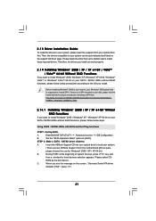
...http://www.microsoft.com/Windows2000/downloads/servicepacks/sp4/spdeploy. Please follow below steps. STEP 2: Make a SATA / SATAII driver diskette. Insert the ASRock Support CD into your optical drive to boot your system can work properly. 2.14 Installing Windows® 2000 / XP / XP 64-bit...on the screen, "Generate Serial ATA driver diskette [YN]?", press . 31 A. Enter BIOS SETUP UTILITY Advanced screen IDE Configuration. C. Then, the drivers compatible to your system. (There are two ASRock Support CD in your optical drive first. B. A. ROM as the boot device. When ...
...http://www.microsoft.com/Windows2000/downloads/servicepacks/sp4/spdeploy. Please follow below steps. STEP 2: Make a SATA / SATAII driver diskette. Insert the ASRock Support CD into your optical drive to boot your system can work properly. 2.14 Installing Windows® 2000 / XP / XP 64-bit...on the screen, "Generate Serial ATA driver diskette [YN]?", press . 31 A. Enter BIOS SETUP UTILITY Advanced screen IDE Configuration. C. Then, the drivers compatible to your system. (There are two ASRock Support CD in your optical drive first. B. A. ROM as the boot device. When ...

User Manual
Page 32
... to the mode you choose and the OS you can start to install Windows® 2000 / XP / XP 64-bit on your system. Enter BIOS SETUP UTILITY Advanced screen IDE Configuration. Set the "SATA Operation Mode" option to install a third-party AHCI driver. Generate RAID Driver diskette for WindowsXP64 ... 2: Install Windows® 2000 / XP / XP 64-bit OS on your SATA / SATAII HDDs without NCQ and Hot Plug functions STEP 1: Set Up BIOS. B. D. Select the driver to install according to the OS you want to continue Please insert a floppy diskette into the floppy diskette.
... to the mode you choose and the OS you can start to install Windows® 2000 / XP / XP 64-bit on your system. Enter BIOS SETUP UTILITY Advanced screen IDE Configuration. Set the "SATA Operation Mode" option to install a third-party AHCI driver. Generate RAID Driver diskette for WindowsXP64 ... 2: Install Windows® 2000 / XP / XP 64-bit OS on your SATA / SATAII HDDs without NCQ and Hot Plug functions STEP 1: Set Up BIOS. B. D. Select the driver to install according to the OS you want to continue Please insert a floppy diskette into the floppy diskette.

User Manual
Page 33
...the one for proper procedures of making a SP4 disk: http://www.microsoft.com/Windows2000/downloads/servicepacks/sp4/spdeploy. B. page, please insert the ASRock Support CD into the optical drive again to load the NVIDIA® AHCI drivers. Set the "SATA Operation Mode" option to [AHCI]. ...STEP 1: Set Up BIOS. B. NVIDIA® AHCI drivers are in the following path in our Support CD: (There are two ASRock Support CD in your Windows® 2000 optical disk is supposed to install Windows® ...
...the one for proper procedures of making a SP4 disk: http://www.microsoft.com/Windows2000/downloads/servicepacks/sp4/spdeploy. B. page, please insert the ASRock Support CD into the optical drive again to load the NVIDIA® AHCI drivers. Set the "SATA Operation Mode" option to [AHCI]. ...STEP 1: Set Up BIOS. B. NVIDIA® AHCI drivers are in the following path in our Support CD: (There are two ASRock Support CD in your Windows® 2000 optical disk is supposed to install Windows® ...

User Manual
Page 34
...2000 / Windows® XP / Windows® XP 64-bit on your SATA / SATAII HDDs with RAID functions, please follow below : A. ASRock website http://www.asrock.com 34 Set the "SATA Operation Mode" option to [IDE]. Select the drivers to install a third-party RAID driver. NVIDIA RAID Driver (...required) B. STEP 3: Set Up BIOS. Before you start to install Windows® 2000 / Windows® XP / Windows® XP 64-bit...
...2000 / Windows® XP / Windows® XP 64-bit on your SATA / SATAII HDDs with RAID functions, please follow below : A. ASRock website http://www.asrock.com 34 Set the "SATA Operation Mode" option to [IDE]. Select the drivers to install a third-party RAID driver. NVIDIA RAID Driver (...required) B. STEP 3: Set Up BIOS. Before you start to install Windows® 2000 / Windows® XP / Windows® XP 64-bit...
User Manual
Page 35
... the BIOS RAID installation guide part of BIOS setup to the warning on page 8 for Windows® VistaTM / VistaTM 64-bit.) .. \ I386 \ RAID_Vista (For Windows® VistaTM OS) .. \ AMD64\ RAID_Vista64 (For Windows® VistaTM 64-bit OS) After that FSB can operate under a more stable overclocking environment. page, please insert the ASRock Support...
... the BIOS RAID installation guide part of BIOS setup to the warning on page 8 for Windows® VistaTM / VistaTM 64-bit.) .. \ I386 \ RAID_Vista (For Windows® VistaTM OS) .. \ AMD64\ RAID_Vista64 (For Windows® VistaTM 64-bit OS) After that FSB can operate under a more stable overclocking environment. page, please insert the ASRock Support...

User Manual
Page 36
... to locate and load the Operating System Security To set up the computer. Please press during the Power-On-Self-Test (POST) to enter the BIOS SETUP UTILITY, otherwise, POST will continue with the following selections: Main To set up the system time/date information Advanced To set up the advanced... are for reference purpose only, and they may not exactly match what you see on the menu bar, and then press to configure your screen. 3.1.1 BIOS Menu Bar The top of the screen has a menu bar with its test routines. 3. The Flash Memory on . You may also restart by pressing the...
... to locate and load the Operating System Security To set up the computer. Please press during the Power-On-Self-Test (POST) to enter the BIOS SETUP UTILITY, otherwise, POST will continue with the following selections: Main To set up the system time/date information Advanced To set up the advanced... are for reference purpose only, and they may not exactly match what you see on the menu bar, and then press to configure your screen. 3.1.1 BIOS Menu Bar The top of the screen has a menu bar with its test routines. 3. The Flash Memory on . You may also restart by pressing the...

User Manual
Page 37
... Main Smart Advanced H/W Monitor Boot Security Exit System Overview System Time System Date [14:00:09] [Tue 09/02/2008] BIOS Version : N68PV-GS P1.00 Processor Type : AMD Athlon(tm) Dual Core Processor 4450e (64bit) Processor Speed : 2300MHz Microcode Update : 60FB2/0 L1 Cache Size : 256KB L2 Cache ... the function description of each navigation key. 3.1.2 Navigation Keys Please check the following table for all the settings To save changes and exit the BIOS SETUP UTILITY To jump to specify the system time. System Date [Day Month/Date/Year] Use this item to the Exit Screen or exit...
... Main Smart Advanced H/W Monitor Boot Security Exit System Overview System Time System Date [14:00:09] [Tue 09/02/2008] BIOS Version : N68PV-GS P1.00 Processor Type : AMD Athlon(tm) Dual Core Processor 4450e (64bit) Processor Speed : 2300MHz Microcode Update : 60FB2/0 L1 Cache Size : 256KB L2 Cache ... the function description of each navigation key. 3.1.2 Navigation Keys Please check the following table for all the settings To save changes and exit the BIOS SETUP UTILITY To jump to specify the system time. System Date [Day Month/Date/Year] Use this item to the Exit Screen or exit...

User Manual
Page 38
...all system configurations. Load Power Saving Setup Default Load power saving setup default. BIOS SETUP UTILITY Main Smart Advanced H/W Monitor Boot Security Exit Smart Settings Save Changes and Exit Load BIOS Defaults Load Performance Setup Default (IDE/SATA) Load Performance Setup AHCI Mode Load... default settings. F6 key can be used for this operation. F10 key can be used for all system configurations. Load BIOS Defaults Load BIOS default values for this operation. If system boot failure occurs after loading, please resume optimal default settings. Select Screen Select ...
...all system configurations. Load Power Saving Setup Default Load power saving setup default. BIOS SETUP UTILITY Main Smart Advanced H/W Monitor Boot Security Exit Smart Settings Save Changes and Exit Load BIOS Defaults Load Performance Setup Default (IDE/SATA) Load Performance Setup AHCI Mode Load... default settings. F6 key can be used for this operation. F10 key can be used for all system configurations. Load BIOS Defaults Load BIOS default values for this operation. If system boot failure occurs after loading, please resume optimal default settings. Select Screen Select ...
User Manual
Page 39
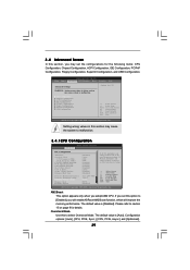
..., PCIPnP Configuration, Floppy Configuration, SuperIO Configuration, and USB Configuration. AM2 Boost This option appears only when you will enable ASRock AM2 Boost function, which will be set based on page 9 for CPU WARNING : Setting wrong values in below sections may...and voltage will improve the memory performance. Configuration options: [Auto], [CPU, PCIE, Sync.], [CPU, PCIE, Async.] and [Optimized]. 39 BIOS SETUP UTILITY Main Smart Advanced H/W Monitor Boot Security Exit Advanced Settings Options for details. The default value is [Disabled]. 3.4 Advanced Screen In this...
..., PCIPnP Configuration, Floppy Configuration, SuperIO Configuration, and USB Configuration. AM2 Boost This option appears only when you will enable ASRock AM2 Boost function, which will be set based on page 9 for CPU WARNING : Setting wrong values in below sections may...and voltage will improve the memory performance. Configuration options: [Auto], [CPU, PCIE, Sync.], [CPU, PCIE, Async.] and [Optimized]. 39 BIOS SETUP UTILITY Main Smart Advanced H/W Monitor Boot Security Exit Advanced Settings Options for details. The default value is [Disabled]. 3.4 Advanced Screen In this...

User Manual
Page 41
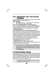
.... Processor Target Frequency This option appears only when you adopt Phenom CPU. North Bridge Target Frequency This option appears only when you adopt Phenom CPU. BIOS SETUP UTILITY Advanced CPU Configuration AM2 Boost Overclock Mode CPU Frequency (MHz) PCIE Frequency (MHz) CPU/LDT Spread Spectrum PCIE Spread Spectrum SATA Spread Spectrum...
.... Processor Target Frequency This option appears only when you adopt Phenom CPU. North Bridge Target Frequency This option appears only when you adopt Phenom CPU. BIOS SETUP UTILITY Advanced CPU Configuration AM2 Boost Overclock Mode CPU Frequency (MHz) PCIE Frequency (MHz) CPU/LDT Spread Spectrum PCIE Spread Spectrum SATA Spread Spectrum...


