User Manual
Page 3
... ...Motherboard Layout (N68-VGS3 UCC / N68-VS3 UCC) ...I/O Panel (N68-VGS3 UCC) ...I/O Panel (N68-VS3 UCC) ...5 6 11 12 13 14 15 15 16 17 18 19 20 24 25 25 26 28 28 28 29 30 30 31 31 32 38 39 40 41 43 45 46 2 . Contents 1 . BIOS S ETUP UTILITY ...30 SETUP 3.2 3.3 3.4 3 Installation ...14 Pre-installation Precautions ...2.1 CPU Installation ...2.2 Installation...
... ...Motherboard Layout (N68-VGS3 UCC / N68-VS3 UCC) ...I/O Panel (N68-VGS3 UCC) ...I/O Panel (N68-VS3 UCC) ...5 6 11 12 13 14 15 15 16 17 18 19 20 24 25 25 26 28 28 28 29 30 30 31 31 32 38 39 40 41 43 45 46 2 . Contents 1 . BIOS S ETUP UTILITY ...30 SETUP 3.2 3.3 3.4 3 Installation ...14 Pre-installation Precautions ...2.1 CPU Installation ...2.2 Installation...
User Manual
Page 5
.... You may find the latest VGA cards and CPU support lists on ASRock website without notice. www.asrock.com/support/index.asp 1.1 P ack age Contents ackage One ASRock N68-VGS3 UCC / N68-VS3 UCC Motherboard (Micro ATX Form Factor: 8.5-in x 7.0-in, 21.6 cm x 17.8 cm) One ASRock N68-VGS3 UCC / N68-VS3 UCC Quick Installation Guide One ASRock N68-VGS3 UCC / N68-VS3 UCC Support CD Two Serial ATA (SATA) Data...
.... You may find the latest VGA cards and CPU support lists on ASRock website without notice. www.asrock.com/support/index.asp 1.1 P ack age Contents ackage One ASRock N68-VGS3 UCC / N68-VS3 UCC Motherboard (Micro ATX Form Factor: 8.5-in x 7.0-in, 21.6 cm x 17.8 cm) One ASRock N68-VGS3 UCC / N68-VS3 UCC Quick Installation Guide One ASRock N68-VGS3 UCC / N68-VS3 UCC Support CD Two Serial ATA (SATA) Data...
User Manual
Page 6
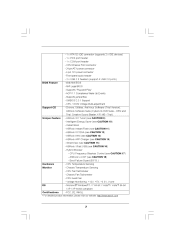
...; GeForce 7025 graphics - Max. Supports D-Sub with LED (ACT/LINK LED and SPEED LED) - Supports Six-Core CPU - NVIDIA® GeForce 7025 / nForce 630a - N68-VGS3 UCC Realtek Giga PHY RTL8211CL, speed 10/100/1000 Mb/s - Max. N68-VS3 UCC Realtek PHY RTL8201EL, speed 10/100 Mb/s - Dual Channel DDR3 Memory Technology (see CAUTION 2) - Support DDR3...
...; GeForce 7025 graphics - Max. Supports D-Sub with LED (ACT/LINK LED and SPEED LED) - Supports Six-Core CPU - NVIDIA® GeForce 7025 / nForce 630a - N68-VGS3 UCC Realtek Giga PHY RTL8211CL, speed 10/100/1000 Mb/s - Max. N68-VS3 UCC Realtek PHY RTL8201EL, speed 10/100 Mb/s - Dual Channel DDR3 Memory Technology (see CAUTION 2) - Support DDR3...
User Manual
Page 7
... Support CD Unique Feature Hardware Monitor OS Certifications - 1 x ATA133 IDE connector (supports 2 x IDE devices) - 1 x Print port header - 1 x COM port header - ASRock Instant Flash (see CAUTION 15) - CPU Quiet Fan - CPU Temperature Sensing - CPU/Chassis FAN connector - 24 pin ATX power connector - 4 pin 12V power connector - Hybrid Booster: - SmartView (see CAUTION 11) - FCC, CE, WHQL...
... Support CD Unique Feature Hardware Monitor OS Certifications - 1 x ATA133 IDE connector (supports 2 x IDE devices) - 1 x Print port header - 1 x COM port header - ASRock Instant Flash (see CAUTION 15) - CPU Quiet Fan - CPU Temperature Sensing - CPU/Chassis FAN connector - 24 pin ATX power connector - 4 pin 12V power connector - Hybrid Booster: - SmartView (see CAUTION 11) - FCC, CE, WHQL...
User Manual
Page 8
... BIOS, applying Untied Overclocking Technology, or using the thirdparty overclocking tools. ASRock website http://www.asrock.com UCC (Unlock CPU Core) feature simplifies AMD CPU activation. If you can enjoy the upgrade CPU performance with overclocking, including adjusting the setting in addition, not every AM3 CPU can also connect SATA hard disk to SATAII connector directly. 9. Please...
... BIOS, applying Untied Overclocking Technology, or using the thirdparty overclocking tools. ASRock website http://www.asrock.com UCC (Unlock CPU Core) feature simplifies AMD CPU activation. If you can enjoy the upgrade CPU performance with overclocking, including adjusting the setting in addition, not every AM3 CPU can also connect SATA hard disk to SATAII connector directly. 9. Please...
User Manual
Page 9
...first utility to turn your OC settings as a game joystick to improve efficiency when the CPU cores are idle. Also, please do not forget to pay attention to ASRock official website regularly, we will continuously provide you can press key during the POST or press...this utility, you have to your overclocking record under the operating system and simplifies the complicated recording process of PC gaming operation. ASRock Instant Flash is capable of Intelligent Energy Saver. The software name itself - To experience intuitive motion controlled games is a revolutionary ...
...first utility to turn your OC settings as a game joystick to improve efficiency when the CPU cores are idle. Also, please do not forget to pay attention to ASRock official website regularly, we will continuously provide you can press key during the POST or press...this utility, you have to your overclocking record under the operating system and simplifies the complicated recording process of PC gaming operation. ASRock Instant Flash is capable of Intelligent Energy Saver. The software name itself - To experience intuitive motion controlled games is a revolutionary ...
User Manual
Page 10
... this motherboard offers stepless control, it back again. While CPU overheat is not recommended to spray thermal grease between the CPU and the heatsink when you to 40% faster than ever. ASRock website: http://www.asrock.com/Feature/AppCharger/index.asp 15. ASRock website: http://www.asrock.com/Feature/SmartView/index.asp 16. SmartView, a new function...
... this motherboard offers stepless control, it back again. While CPU overheat is not recommended to spray thermal grease between the CPU and the heatsink when you to 40% faster than ever. ASRock website: http://www.asrock.com/Feature/AppCharger/index.asp 15. ASRock website: http://www.asrock.com/Feature/SmartView/index.asp 16. SmartView, a new function...
User Manual
Page 11
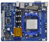
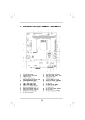
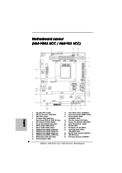
...x16 Slot (PCIE1) Front Panel Audio Header (HD_AUDIO1, Lime) ATX 12V Power Connector (ATX12V1) AM3 CPU Socket ATX Power Connector (ATXPWR1) 11 1.3 Motherboard L ayout (N68VGS3 UCC / N68VS3 UCC) Layout (N68-VGS3 N68-VS3 1 17.8cm (7.0-in) 2 3 Support 6-Core CPU 1 PS2_USB_PWR1 USB 2.0 T: USB2 B: USB3 21.6cm (8.5-in) 26 ATXPWR1 PS2 Keyboard PS2 Mouse ... 1 PLED PWRBTN 1 CLRCMOS1 SPEAKER1 21 1 1 1 HDLED RESET PCI1 1 LPT1 16 20 1 2 3 4 5 6 7 8 9 10 11 12 13 14 PS2_USB_PWR1 Jumper CPU Fan Connector (CPU_FAN1) USB_PWR2 Jumper 2 x 240-pin DDR3 DIMM Slots (Dual Channel: DDR3_A1, DDR3_B1;
...x16 Slot (PCIE1) Front Panel Audio Header (HD_AUDIO1, Lime) ATX 12V Power Connector (ATX12V1) AM3 CPU Socket ATX Power Connector (ATXPWR1) 11 1.3 Motherboard L ayout (N68VGS3 UCC / N68VS3 UCC) Layout (N68-VGS3 N68-VS3 1 17.8cm (7.0-in) 2 3 Support 6-Core CPU 1 PS2_USB_PWR1 USB 2.0 T: USB2 B: USB3 21.6cm (8.5-in) 26 ATXPWR1 PS2 Keyboard PS2 Mouse ... 1 PLED PWRBTN 1 CLRCMOS1 SPEAKER1 21 1 1 1 HDLED RESET PCI1 1 LPT1 16 20 1 2 3 4 5 6 7 8 9 10 11 12 13 14 PS2_USB_PWR1 Jumper CPU Fan Connector (CPU_FAN1) USB_PWR2 Jumper 2 x 240-pin DDR3 DIMM Slots (Dual Channel: DDR3_A1, DDR3_B1;
User Manual
Page 15
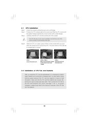
...you push down the socket lever to a 90 angle. Make sure that the CPU and the heatsink are securely fastened and in good contact with a small triangle. Step 3. The CPU fits only in place. Position the CPU directly above the socket such that it is locked. You also need to ... Push Down And Lock The Socket Lever 2.2 Installation of the CPU fan and the heatsink. 15 For proper installation, please kindly refer to dissipate heat. CPU Installation Unlock the socket by lifting the lever up to secure the CPU. When the CPU is necessary to install a larger heatsink and cooling fan to...
...you push down the socket lever to a 90 angle. Make sure that the CPU and the heatsink are securely fastened and in good contact with a small triangle. Step 3. The CPU fits only in place. Position the CPU directly above the socket such that it is locked. You also need to ... Push Down And Lock The Socket Lever 2.2 Installation of the CPU fan and the heatsink. 15 For proper installation, please kindly refer to dissipate heat. CPU Installation Unlock the socket by lifting the lever up to secure the CPU. When the CPU is necessary to install a larger heatsink and cooling fan to...
User Manual
Page 22
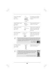
...Chassis Fan Connector (3-pin CHA_FAN1) (see p.11 No. 17) 1 SPEAKER DUMMY DUMMY +5V Please connect the chassis speaker to the ground pin. 1 2 3 4 CPU Fan Connector (4-pin CPU_FAN1) (see p.11 No. 16) 1 PLED+ PLEDPWRBTN# GND This header accommodates several system front panel functions. DUMMY RESET# GND HDLEDHDLED+ Chassis... (4-pin SPEAKER 1) (see p.11 No. 19) Please connect a chassis fan cable to this connector and match the black wire to the CPU fan connector on this motherboard, please connect it can work if you adopt a traditional 20-pin ATX power supply. If you plan to connect...
...Chassis Fan Connector (3-pin CHA_FAN1) (see p.11 No. 17) 1 SPEAKER DUMMY DUMMY +5V Please connect the chassis speaker to the ground pin. 1 2 3 4 CPU Fan Connector (4-pin CPU_FAN1) (see p.11 No. 16) 1 PLED+ PLEDPWRBTN# GND This header accommodates several system front panel functions. DUMMY RESET# GND HDLEDHDLED+ Chassis... (4-pin SPEAKER 1) (see p.11 No. 19) Please connect a chassis fan cable to this connector and match the black wire to the CPU fan connector on this motherboard, please connect it can work if you adopt a traditional 20-pin ATX power supply. If you plan to connect...
User Manual
Page 29
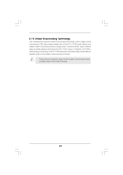
... PCI / PCIE buses are in the fixed mode so that FSB can operate under a more stable overclocking environment. Therefore, CPU FSB is untied during overclocking, FSB enjoys better margin due to [CPU, PCIE, Async.]. Please refer to the warning on page 8 for the possible overclocking risk before you enable Untied Overclocking function...
... PCI / PCIE buses are in the fixed mode so that FSB can operate under a more stable overclocking environment. Therefore, CPU FSB is untied during overclocking, FSB enjoys better margin due to [CPU, PCIE, Async.]. Please refer to the warning on page 8 for the possible overclocking risk before you enable Untied Overclocking function...
User Manual
Page 32
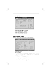
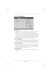
... Spread Spectrum SATA Spread Spectrum ASRock UCC CPU Active Core Control BIOS SETUP UTILITY Advanced H/W Monitor Boot Security Exit Overclocking may cause damage to select Overclock Mode. CPU Configuration Overclock Mode Use this to your own risk and expense. N68-VS3 UCC OC Tweaker BIOS SETUP UTILITY ...to specify the system time. Use [+] or [-] to adjust PCIE frequency. 32 The default value is [Auto]. CPU Frequency (MHz) Use this option to configure system Time. : N68-VS3 UCC P1.00 : AMD Athlon (tm) II X2 265 Processor (64bit) Processor Speed : 3300MHz Microcode Update : ...
... Spread Spectrum SATA Spread Spectrum ASRock UCC CPU Active Core Control BIOS SETUP UTILITY Advanced H/W Monitor Boot Security Exit Overclocking may cause damage to select Overclock Mode. CPU Configuration Overclock Mode Use this to your own risk and expense. N68-VS3 UCC OC Tweaker BIOS SETUP UTILITY ...to specify the system time. Use [+] or [-] to adjust PCIE frequency. 32 The default value is [Auto]. CPU Frequency (MHz) Use this option to configure system Time. : N68-VS3 UCC P1.00 : AMD Athlon (tm) II X2 265 Processor (64bit) Processor Speed : 3300MHz Microcode Update : ...
User Manual
Page 33
...by default. Multiplier/Voltage Change This item is set to the quadcore CPU, and some CPU's hidden core may adjust the value of the BIOS option "ASRock UCC", you can unlock the extra CPU core to keep the default value for reference. If it is [...Disabled]. SATA Spread Spectrum This feature will display Processor Maximum Voltage for system stability. 33 ASRock UCC ASRock UCC (Unlock CPU Core) feature simplifies AMD CPU activation. The configuration options depend on the CPU core you to [Enabled] as a simple switch of Processor Frequency and Processor Voltage. Configuration ...
...by default. Multiplier/Voltage Change This item is set to the quadcore CPU, and some CPU's hidden core may adjust the value of the BIOS option "ASRock UCC", you can unlock the extra CPU core to keep the default value for reference. If it is [...Disabled]. SATA Spread Spectrum This feature will display Processor Maximum Voltage for system stability. 33 ASRock UCC ASRock UCC (Unlock CPU Core) feature simplifies AMD CPU activation. The configuration options depend on the CPU core you to [Enabled] as a simple switch of Processor Frequency and Processor Voltage. Configuration ...
User Manual
Page 34
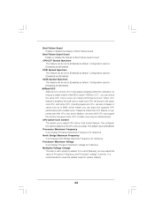
...recommended to adjust the value of this item. NB Frequency Multiplier For safety and system stability, it is [Auto]. 34 Main OC Tweaker CPU Configuration BIOS SETUP UTILITY Advanced H/W Monitor Boot Security Exit [Auto] [200] [100] [Enabled] [3] [Enabled] [Enabled] [Enabled] ...Voltage Change [x0.5 100 MHz] CPU Frequency Multiplier [0.6000 V] Processor Voltage Overclock Mode CPU Frequency (MHz) PCIE Frequency (MHz) Boot Failure Guard Boot Failure Guard Count CPU/LDT Spread Spectrum PCIE Spread Spectrum SATA Spread Spectrum ASRock UCC CPU Active Core Control Overclocking may cause damage...
...recommended to adjust the value of this item. NB Frequency Multiplier For safety and system stability, it is [Auto]. 34 Main OC Tweaker CPU Configuration BIOS SETUP UTILITY Advanced H/W Monitor Boot Security Exit [Auto] [200] [100] [Enabled] [3] [Enabled] [Enabled] [Enabled] ...Voltage Change [x0.5 100 MHz] CPU Frequency Multiplier [0.6000 V] Processor Voltage Overclock Mode CPU Frequency (MHz) PCIE Frequency (MHz) Boot Failure Guard Boot Failure Guard Count CPU/LDT Spread Spectrum PCIE Spread Spectrum SATA Spread Spectrum ASRock UCC CPU Active Core Control Overclocking may cause damage...
User Manual
Page 35
... node, or accross nodes, decreasing access contention. Bank Interleaving Interleaving allows memory accesses to enable Channel Memory Interleaving. Channel Interleaving This allows you adopt Phenom CPU. The default value is [Auto]. CAS Latency (CL) Use this to adjust the means of memory accessing. The default value is [Hash 2]. TWTR Use this...
... node, or accross nodes, decreasing access contention. Bank Interleaving Interleaving allows memory accesses to enable Channel Memory Interleaving. Channel Interleaving This allows you adopt Phenom CPU. The default value is [Auto]. CAS Latency (CL) Use this to adjust the means of memory accessing. The default value is [Hash 2]. TWTR Use this...
User Manual
Page 38
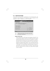
.... Setting wrong values in below sections may cause the system to malfunction. This convenient BIOS update tool allows you execute ASRock Instant Flash utility, the utility will show the BIOS files and their respective information. CPU Configuration Chipset Configuration ACPI Configuration Storage Configuration PCIPnP Configuration SuperIO Configuration USB Configuration BIOS Update Utility...
.... Setting wrong values in below sections may cause the system to malfunction. This convenient BIOS update tool allows you execute ASRock Instant Flash utility, the utility will show the BIOS files and their respective information. CPU Configuration Chipset Configuration ACPI Configuration Storage Configuration PCIPnP Configuration SuperIO Configuration USB Configuration BIOS Update Utility...
User Manual
Page 39
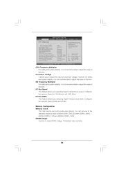
... Help Load Defaults Save and Exit Exit +F1 F9 F10 ESC v02.54 (C) Copyright 1985-2003, American Megatrends, Inc. 3.4.1 CPU Configuration BIOS SETUP UTILITY Advanced CPU Configuration Cool 'n' Quiet Secure Virtual Machine Enhanced Halt State (C1E) L3 Cache Allocation [Auto] [Enabled] [Disabled] [Auto]... Enabling this function may reduce CPU voltage and memory frequency, and lead to system stability or compatibility issue with some memory modules or power supplies. Please note that enabling this function may reduce CPU voltage and memory freq., and lead to system stability...
... Help Load Defaults Save and Exit Exit +F1 F9 F10 ESC v02.54 (C) Copyright 1985-2003, American Megatrends, Inc. 3.4.1 CPU Configuration BIOS SETUP UTILITY Advanced CPU Configuration Cool 'n' Quiet Secure Virtual Machine Enhanced Halt State (C1E) L3 Cache Allocation [Auto] [Enabled] [Disabled] [Auto]... Enabling this function may reduce CPU voltage and memory frequency, and lead to system stability or compatibility issue with some memory modules or power supplies. Please note that enabling this function may reduce CPU voltage and memory freq., and lead to system stability...
User Manual
Page 40
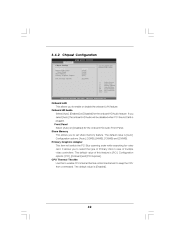
...[Enabled]. 40 Front Panel Select [Auto] or [Disabled] for the onboard HD Audio feature. The default value of multiple video controllers. CPU Thermal Throttle Use this feature is plugged. 3 . 4 . 2 Chipset Configuration BIOS SETUP UTILITY Advanced Chipset Settings Onboard LAN Onboard HD Audio... Front Panel Share Memory Primary Graphics Adapter CPU Thermal Throttle [Enabled] [Auto] [Auto] [Auto] [PCI] [Enabled] Select Screen Select Item Change Option General Help Load Defaults Save and...
...[Enabled]. 40 Front Panel Select [Auto] or [Disabled] for the onboard HD Audio feature. The default value of multiple video controllers. CPU Thermal Throttle Use this feature is plugged. 3 . 4 . 2 Chipset Configuration BIOS SETUP UTILITY Advanced Chipset Settings Onboard LAN Onboard HD Audio... Front Panel Share Memory Primary Graphics Adapter CPU Thermal Throttle [Enabled] [Auto] [Auto] [Auto] [PCI] [Enabled] Select Screen Select Item Change Option General Help Load Defaults Save and...
User Manual
Page 48
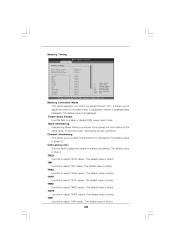
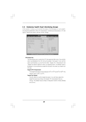
... the target fan speed. The default value is [Fast]. You can freely adjust the target fan speed according to control the CPU fan speed and fan noise. 3.5 Hardware Health Event Monitoring Screen In this section, it allows you to enable this function only... options: [Fast], [Middle] and [Slow]. 48 BIOS SETUP UTILITY Boot Advanced H/W Monitor Security Exit Main OC Tweaker Hardware Health Event Monitoring CPU Temperature M / B Temperature CPU Fan Speed Chassis Fan Speed Vcore + 3.30V + 5.00V + 12.00V CPU Quiet Fan : 37 C / 98 F : 27 C / 80 F : 4722 RPM : N/A : : : : 1.216V 3.248V...
... the target fan speed. The default value is [Fast]. You can freely adjust the target fan speed according to control the CPU fan speed and fan noise. 3.5 Hardware Health Event Monitoring Screen In this section, it allows you to enable this function only... options: [Fast], [Middle] and [Slow]. 48 BIOS SETUP UTILITY Boot Advanced H/W Monitor Security Exit Main OC Tweaker Hardware Health Event Monitoring CPU Temperature M / B Temperature CPU Fan Speed Chassis Fan Speed Vcore + 3.30V + 5.00V + 12.00V CPU Quiet Fan : 37 C / 98 F : 27 C / 80 F : 4722 RPM : N/A : : : : 1.216V 3.248V...
Quick Installation Guide
Page 2
Blue) 5 CPU Heatsink Retention Module 6 Primary IDE Connector (IDE1, Blue) 7 USB 2.0 Header (USB6_7, Blue) 8 USB 2.0 Header (USB4_5, Blue) 9 SATAII Connector (SATAII_2 (PORT 0.1)) 10 SATAII ...Express x16 Slot (PCIE1) 23 Front Panel Audio Header (HD_AUDIO1, Lime) 24 ATX 12V Power Connector (ATX12V1) 25 AM3 CPU Socket 26 ATX Power Connector (ATXPWR1) 2 ASRock N68-VGS3 UCC / N68-VS3 UCC Motherboard Motherboard Layout (N68-VGS3 UCC / N68-VS3 UCC) English 1 PS2_USB_PWR1 Jumper 2 CPU Fan Connector (CPU_FAN1) 3 USB_PWR2 Jumper 4 2 x 240-pin DDR3 DIMM Slots (Dual Channel: DDR3_A1, DDR3_B1;
Blue) 5 CPU Heatsink Retention Module 6 Primary IDE Connector (IDE1, Blue) 7 USB 2.0 Header (USB6_7, Blue) 8 USB 2.0 Header (USB4_5, Blue) 9 SATAII Connector (SATAII_2 (PORT 0.1)) 10 SATAII ...Express x16 Slot (PCIE1) 23 Front Panel Audio Header (HD_AUDIO1, Lime) 24 ATX 12V Power Connector (ATX12V1) 25 AM3 CPU Socket 26 ATX Power Connector (ATXPWR1) 2 ASRock N68-VGS3 UCC / N68-VS3 UCC Motherboard Motherboard Layout (N68-VGS3 UCC / N68-VS3 UCC) English 1 PS2_USB_PWR1 Jumper 2 CPU Fan Connector (CPU_FAN1) 3 USB_PWR2 Jumper 4 2 x 240-pin DDR3 DIMM Slots (Dual Channel: DDR3_A1, DDR3_B1;


