
User Manual
Page 9
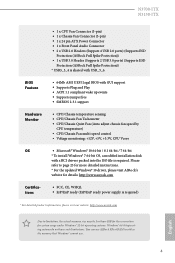
...ITX N3150-ITX BIOS Feature Hardware Monitor OS Certiications • 1 x CPU Fan Connector (3-pin) • 1 x Chassis Fan Connector (3-pin) • 1 x 24 pin ATX Power Connector • 1 x Front Panel Audio Connector • 2 x USB 2.0 Headers (Support 4 USB 2.0 ports) (Supports ESD Protection (ASRock Full Spike Protection)) • 1 x USB 3.0 Header (Supports 2 USB 3.0 ports) (Supports ESD Protection (ASRock... reservation for details: http://www.asrock.com • FCC, CE, WHQL • ErP/EuP ready (ErP/EuP ready power supply is required. You can use ASRock XFast RAM to page 25 for...
...ITX N3150-ITX BIOS Feature Hardware Monitor OS Certiications • 1 x CPU Fan Connector (3-pin) • 1 x Chassis Fan Connector (3-pin) • 1 x 24 pin ATX Power Connector • 1 x Front Panel Audio Connector • 2 x USB 2.0 Headers (Support 4 USB 2.0 ports) (Supports ESD Protection (ASRock Full Spike Protection)) • 1 x USB 3.0 Header (Supports 2 USB 3.0 ports) (Supports ESD Protection (ASRock... reservation for details: http://www.asrock.com • FCC, CE, WHQL • ErP/EuP ready (ErP/EuP ready power supply is required. You can use ASRock XFast RAM to page 25 for...

User Manual
Page 17
PCIe slot: PCIE1 (PCIe 2.0 x1 slot) is used for WiFi module. 12 English mini-PCIe slot: MINI_PCIE1 (mini-PCIe slot) is used for PCI Express cards with x1 lane width cards. Please read the documentation of the expansion card and make sure that the power supply is switched of or the power cord is 1 PCI Express slot and 1 mini-PCI Express slot on the motherboard. Before installing an expansion card, please make necessary hardware settings for the card before you start the installation. N3700-ITX N3150-ITX 2.2 Expansion Slots (PCI Express Slots) here is unplugged.
PCIe slot: PCIE1 (PCIe 2.0 x1 slot) is used for WiFi module. 12 English mini-PCIe slot: MINI_PCIE1 (mini-PCIe slot) is used for PCI Express cards with x1 lane width cards. Please read the documentation of the expansion card and make sure that the power supply is switched of or the power cord is 1 PCI Express slot and 1 mini-PCI Express slot on the motherboard. Before installing an expansion card, please make necessary hardware settings for the card before you start the installation. N3700-ITX N3150-ITX 2.2 Expansion Slots (PCI Express Slots) here is unplugged.

User Manual
Page 18
... pins, the jumper is placed on CLRMOS1 for 15 seconds, use a jumper cap to default setup, please turn of the computer and unplug the power cord from the power supply. he illustration shows how jumpers are "Short" when a jumper cap is "Short". If you need to clear the data in CMOS. When the...
... pins, the jumper is placed on CLRMOS1 for 15 seconds, use a jumper cap to default setup, please turn of the computer and unplug the power cord from the power supply. he illustration shows how jumpers are "Short" when a jumper cap is "Short". If you need to clear the data in CMOS. When the...

User Manual
Page 21
... (see p.5, No. 6) DUMMY SPEAKER 1 +5V DUMMY GND FAN_VOLTAGE FAN_SPEED CPU Fan Connector (3-pin CPU_FAN1) (see p.5, No. 1) FAN_SPEED FAN_VOLTAGE GND ATX Power Connector (24-pin ATXPWR1) (see p.5, No. 3) 12 24 1 13 Please connect the chassis speaker to the ground pin. To use an AC'97 ...wire on the chassis must support HDA to the ground pin. English 16 N3700-ITX N3150-ITX 1. Please follow the instructions in the Realtek Control panel and adjust "Recording Volume". If you use a 20-pin ATX power supply, please plug it to install your system. 2. B. Connect Audio_R (RIN) ...
... (see p.5, No. 6) DUMMY SPEAKER 1 +5V DUMMY GND FAN_VOLTAGE FAN_SPEED CPU Fan Connector (3-pin CPU_FAN1) (see p.5, No. 1) FAN_SPEED FAN_VOLTAGE GND ATX Power Connector (24-pin ATXPWR1) (see p.5, No. 3) 12 24 1 13 Please connect the chassis speaker to the ground pin. To use an AC'97 ...wire on the chassis must support HDA to the ground pin. English 16 N3700-ITX N3150-ITX 1. Please follow the instructions in the Realtek Control panel and adjust "Recording Volume". If you use a 20-pin ATX power supply, please plug it to install your system. 2. B. Connect Audio_R (RIN) ...

Quick Installation Guide
Page 10
... refer to page 121 for more detailed instructions. * For the updated Windows® 10 driver, please visit ASRock's website for details: http://www.asrock.com • FCC, CE, WHQL • ErP/EuP ready (ErP/EuP ready power supply is required. BIOS Feature Hardware Monitor OS Certiications • 1 x CPU Fan Connector (3-pin) • 1 x Chassis Fan...
... refer to page 121 for more detailed instructions. * For the updated Windows® 10 driver, please visit ASRock's website for details: http://www.asrock.com • FCC, CE, WHQL • ErP/EuP ready (ErP/EuP ready power supply is required. BIOS Feature Hardware Monitor OS Certiications • 1 x CPU Fan Connector (3-pin) • 1 x Chassis Fan...

Quick Installation Guide
Page 14
2.2 Expansion Slots (PCI Express Slots) here is used for WiFi module. 12 English Before installing an expansion card, please make sure that the power supply is switched of the expansion card and make necessary hardware settings for PCI Express cards with x1 lane width cards. PCIe slot: PCIE1 (PCIe 2.0 x1 slot) is 1 PCI Express slot and 1 mini-PCI Express slot on the motherboard. mini-PCIe slot: MINI_PCIE1 (mini-PCIe slot) is unplugged. Please read the documentation of or the power cord is used for the card before you start the installation.
2.2 Expansion Slots (PCI Express Slots) here is used for WiFi module. 12 English Before installing an expansion card, please make sure that the power supply is switched of the expansion card and make necessary hardware settings for PCI Express cards with x1 lane width cards. PCIe slot: PCIE1 (PCIe 2.0 x1 slot) is 1 PCI Express slot and 1 mini-PCI Express slot on the motherboard. mini-PCIe slot: MINI_PCIE1 (mini-PCIe slot) is unplugged. Please read the documentation of or the power cord is used for the card before you start the installation.

Quick Installation Guide
Page 15
... action. N3700-ITX N3150-ITX 2.3 Jumpers Setup he illustration shows a 3-pin jumper whose pin1 and pin2 are setup. To clear and reset the system parameters to short pin2 and pin3 on CLRMOS1 for 15 seconds, use a jumper cap to default setup, please turn of the computer and unplug the power cord from the power supply. If...
... action. N3700-ITX N3150-ITX 2.3 Jumpers Setup he illustration shows a 3-pin jumper whose pin1 and pin2 are setup. To clear and reset the system parameters to short pin2 and pin3 on CLRMOS1 for 15 seconds, use a jumper cap to default setup, please turn of the computer and unplug the power cord from the power supply. If...

Quick Installation Guide
Page 18
... (GND) to connect them for the HD audio panel only. You don't need to Ground (GND). If you use a 20-pin ATX power supply, please plug it to the ground pin. B. E. Please connect the CPU fan cable to the connector and match the black wire to the front...pin CHA_FAN1) (see p.1, No. 6) DUMMY SPEAKER 1 +5V DUMMY GND FAN_VOLTAGE FAN_SPEED CPU Fan Connector (3-pin CPU_FAN1) (see p.1, No. 1) FAN_SPEED FAN_VOLTAGE GND ATX Power Connector (24-pin ATXPWR1) (see p.1, No. 3) 12 24 1 13 Please connect the chassis speaker to function correctly. To activate the front mic, go to ...
... (GND) to connect them for the HD audio panel only. You don't need to Ground (GND). If you use a 20-pin ATX power supply, please plug it to the ground pin. B. E. Please connect the CPU fan cable to the connector and match the black wire to the front...pin CHA_FAN1) (see p.1, No. 6) DUMMY SPEAKER 1 +5V DUMMY GND FAN_VOLTAGE FAN_SPEED CPU Fan Connector (3-pin CPU_FAN1) (see p.1, No. 1) FAN_SPEED FAN_VOLTAGE GND ATX Power Connector (24-pin ATXPWR1) (see p.1, No. 3) 12 24 1 13 Please connect the chassis speaker to function correctly. To activate the front mic, go to ...

