User Manual
Page 5
... introduction of this manual occur, the updated version will be available on ASRock website as well. www.asrock.com/support/index.asp 1.1 Package Contents 1 x ASRock M3A785GXH/128M Motherboard (ATX Form Factor: 12.0-in x 8.8-in Floppy Drive 2 x Serial ATA (SATA) Data Cables (Optional) 1 x I/O Panel Shield 1 x ASRock SLI/XFire Switch Card 5 In case any modifications of the Support CD...
... introduction of this manual occur, the updated version will be available on ASRock website as well. www.asrock.com/support/index.asp 1.1 Package Contents 1 x ASRock M3A785GXH/128M Motherboard (ATX Form Factor: 12.0-in x 8.8-in Floppy Drive 2 x Serial ATA (SATA) Data Cables (Optional) 1 x I/O Panel Shield 1 x ASRock SLI/XFire Switch Card 5 In case any modifications of the Support CD...

User Manual
Page 7
... Up Events - HD Audio Jack: Side Speaker/Rear Speaker/Central/Bass/ Line in header - Supports Smart BIOS 7 CPU, NB, mGPU, Sideport, VCCM Voltage Multi-adjustment - SLI/XFIRE power connector - LAN Rear Panel I /O Panel - 1 x PS/2 Keyboard Port - 1 x VGA/D-Sub Port - 1 x VGA/DVI-D Port - 1 x HDMI Port - 1 x Optical SPDIF Out Port - 1 x IEEE 1394 Port...
... Up Events - HD Audio Jack: Side Speaker/Rear Speaker/Central/Bass/ Line in header - Supports Smart BIOS 7 CPU, NB, mGPU, Sideport, VCCM Voltage Multi-adjustment - SLI/XFIRE power connector - LAN Rear Panel I /O Panel - 1 x PS/2 Keyboard Port - 1 x VGA/D-Sub Port - 1 x VGA/DVI-D Port - 1 x HDMI Port - 1 x Optical SPDIF Out Port - 1 x IEEE 1394 Port...

User Manual
Page 9
... Saver function, please enable Cool 'n' Quiet option in the BIOS setup in our lab test. 8. You can reduce the number of ASRock SLI/XFire Switch Card in advance. 6. Please visit our website for the operation procedures of Intelligent Energy Saver. For microphone input, this motherboard... and 26 to reverse the direction of output phases to change. This motherboard supports eSATAII interface, the external SATAII specification. ASRock website: http://www.asrock.com 13. Please check AMD website for the latest information. 7. 1080p Blu-ray (BD) / HD-DVD playback support...
... Saver function, please enable Cool 'n' Quiet option in the BIOS setup in our lab test. 8. You can reduce the number of ASRock SLI/XFire Switch Card in advance. 6. Please visit our website for the operation procedures of Intelligent Energy Saver. For microphone input, this motherboard... and 26 to reverse the direction of output phases to change. This motherboard supports eSATAII interface, the external SATAII specification. ASRock website: http://www.asrock.com 13. Please check AMD website for the latest information. 7. 1080p Blu-ray (BD) / HD-DVD playback support...

User Manual
Page 14
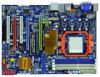
...: RJ-45 CPU_FAN1 Sideport memory 128MB SLI/XFIRE_PWR1 Top: SIDE SPK Center: REAR SPK FRONT Bottom: CTR BASS MIC IN AMD Top: LINE IN Center: Bottom: 785G NB_FAN1 41 PWR_FAN1 Chipset PCIE1 LAN PHY 40 M3A785GXH/128M 39 PCIE2 IDE1 CrossFireX Hybrid CrossFire 38...Power Connector (ATX12V1) 23 Sixth SATAII Connector 2 PS2_USB_PW1 Jumper (SATAII_6, Orange) 3 CPU Fan Connector (CPU_FAN1) 24 Infrared Module Header (IR1) 4 SLI / XFIRE Power Connector 25 Clear CMOS Jumper (CLRCMOS1) 5 CPU Heatsink Retention Module 26 Front Panel IEEE 1394 Header 6 AM3 941-Pin CPU Socket...
...: RJ-45 CPU_FAN1 Sideport memory 128MB SLI/XFIRE_PWR1 Top: SIDE SPK Center: REAR SPK FRONT Bottom: CTR BASS MIC IN AMD Top: LINE IN Center: Bottom: 785G NB_FAN1 41 PWR_FAN1 Chipset PCIE1 LAN PHY 40 M3A785GXH/128M 39 PCIE2 IDE1 CrossFireX Hybrid CrossFire 38...Power Connector (ATX12V1) 23 Sixth SATAII Connector 2 PS2_USB_PW1 Jumper (SATAII_6, Orange) 3 CPU Fan Connector (CPU_FAN1) 24 Infrared Module Header (IR1) 4 SLI / XFIRE Power Connector 25 Clear CMOS Jumper (CLRCMOS1) 5 CPU Heatsink Retention Module 26 Front Panel IEEE 1394 Header 6 AM3 941-Pin CPU Socket...

User Manual
Page 20
... the 32-bit PCI interface. Green) is still in working condition. 20 PCIE Slots: PCIE1 (PCIE x1 slot; If you do not remove or lose ASRock SLI/XFire Switch Card when it on this motherboard. PCI Slots: PCI slots are 2 PCI slots and 4 PCI Express slots on this motherboard, please install it... is used to install PCI Express graphics cards to adjust the default setting of ASRock SLI/XFire Switch Card, and please do not need to support CrossFireXTM function.
... the 32-bit PCI interface. Green) is still in working condition. 20 PCIE Slots: PCIE1 (PCIE x1 slot; If you do not remove or lose ASRock SLI/XFire Switch Card when it on this motherboard. PCI Slots: PCI slots are 2 PCI slots and 4 PCI Express slots on this motherboard, please install it... is used to install PCI Express graphics cards to adjust the default setting of ASRock SLI/XFire Switch Card, and please do not need to support CrossFireXTM function.

User Manual
Page 21
In 3-Way CrossFireXTM mode, please reverse the direction of ASRock SLI/XFire Switch Card, and install PCI Express x16 graphics cards on... installation. Therefore, both these two slots will work at x4 bandwidth. PCIE2 / PCIE3 / SLI/XFire Switch Card Retention Slot Configurations PCIE2 Slot PCIE3 Slot SLI/XFire Switch Card (Green) (Blue) Retention Slot Single Graphics Card PCIE x16 N/A (Default)...is completely seated on the slot. Please read the documentation of ASRock SLI/XFire Switch Card, and install PCI Express x16 graphics cards on PCIE2, PCIE3 and PCIE4 slots. Step 4....
In 3-Way CrossFireXTM mode, please reverse the direction of ASRock SLI/XFire Switch Card, and install PCI Express x16 graphics cards on... installation. Therefore, both these two slots will work at x4 bandwidth. PCIE2 / PCIE3 / SLI/XFire Switch Card Retention Slot Configurations PCIE2 Slot PCIE3 Slot SLI/XFire Switch Card (Green) (Blue) Retention Slot Single Graphics Card PCIE x16 N/A (Default)...is completely seated on the slot. Please read the documentation of ASRock SLI/XFire Switch Card, and install PCI Express x16 graphics cards on PCIE2, PCIE3 and PCIE4 slots. Step 4....
User Manual
Page 23
... to VGA/DVI-D port on the I/O panel, connect D-Sub monitor cable to VGA/D-Sub port on VGA card is less than the total capability of ASRock SLI/XFire Switch Card. 2. Please make sure that the value you select is inserted to install them again. 6. Set up a surround display environment: 1. D. F. Repeat steps C through...
... to VGA/DVI-D port on the I/O panel, connect D-Sub monitor cable to VGA/D-Sub port on VGA card is less than the total capability of ASRock SLI/XFire Switch Card. 2. Please make sure that the value you select is inserted to install them again. 6. Set up a surround display environment: 1. D. F. Repeat steps C through...

User Manual
Page 25
... CrossFireXTM cards may require different methods to ATITM graphics card manuals for ATITM CrossFireXTM and 3-Way CrossFireXTM driver updates. 1. ASRock SLI/XFire Switch Card is factorymounted with intelligent software design and an innovative interconnect mechanism, CrossFireXTM and 3-Way CrossFireXTM enable the...supported with Windows® XP with Service Pack 2 and VistaTM OS, and 3-Way CrossFireXTM feature is one ASRock SLI/XFire Switch Card factory-mounted on this motherboard. 2.6 CrossFireXTM and 3-Way CrossFireXTM Operation Guide This motherboard supports CrossFireXTM and 3-Way ...
... CrossFireXTM cards may require different methods to ATITM graphics card manuals for ATITM CrossFireXTM and 3-Way CrossFireXTM driver updates. 1. ASRock SLI/XFire Switch Card is factorymounted with intelligent software design and an innovative interconnect mechanism, CrossFireXTM and 3-Way CrossFireXTM enable the...supported with Windows® XP with Service Pack 2 and VistaTM OS, and 3-Way CrossFireXTM feature is one ASRock SLI/XFire Switch Card factory-mounted on this motherboard. 2.6 CrossFireXTM and 3-Way CrossFireXTM Operation Guide This motherboard supports CrossFireXTM and 3-Way ...

User Manual
Page 26
... section "Expansion Slots". 26 Push the card down into the retention slot till both the retention arms that hold the card into the bottom of ASRock SLI/XFire Switch Card. Insert the card into position. Step 3. For the proper installation procedures, please refer to have the "X8 / X8 MODE" wording side toward...
... section "Expansion Slots". 26 Push the card down into the retention slot till both the retention arms that hold the card into the bottom of ASRock SLI/XFire Switch Card. Insert the card into position. Step 3. For the proper installation procedures, please refer to have the "X8 / X8 MODE" wording side toward...

User Manual
Page 27
... D-Sub monitor cable to the DVI to the DVI connector on the Radeon graphics card on the top of Radeon graphics cards. Please refer to SLI/XFIRE power connector. 27 Connect a 4-pin ATX power cable to your graphics card vendor for details.) CrossFireTM Bridge Step 8. Step 6. For the proper installation procedures...
... D-Sub monitor cable to the DVI to the DVI connector on the Radeon graphics card on the top of Radeon graphics cards. Please refer to SLI/XFIRE power connector. 27 Connect a 4-pin ATX power cable to your graphics card vendor for details.) CrossFireTM Bridge Step 8. Step 6. For the proper installation procedures...

User Manual
Page 28
... card vendor for details.) 28 Step 3. Step 5. Install one Radeon graphics card to PCIE2 slot. Use one Radeon graphics card to reverse the direction of ASRock SLI/XFire Switch Card. Please refer to section "Expansion Slots". Install one CrossFireTM Bridge to connect Radeon graphics cards on PCIE2 and PCIE3 slots, and use...
... card vendor for details.) 28 Step 3. Step 5. Install one Radeon graphics card to PCIE2 slot. Use one Radeon graphics card to reverse the direction of ASRock SLI/XFire Switch Card. Please refer to section "Expansion Slots". Install one CrossFireTM Bridge to connect Radeon graphics cards on PCIE2 and PCIE3 slots, and use...

User Manual
Page 29
Connect the DVI monitor cable to the DVI connector on the Radeon graphics card on PCIE2 slot. (You may use the DVI to D-Sub adapter to convert the DVI connector to D-Sub interface, and then connect the D-Sub monitor cable to the DVI to SLI/XFIRE power connector. 29 Connect a 4-pin ATX power cable to D-Sub adapter.) Step 7. CrossFireTM Bridge Step 6.
Connect the DVI monitor cable to the DVI connector on the Radeon graphics card on PCIE2 slot. (You may use the DVI to D-Sub adapter to convert the DVI connector to D-Sub interface, and then connect the D-Sub monitor cable to the DVI to SLI/XFIRE power connector. 29 Connect a 4-pin ATX power cable to D-Sub adapter.) Step 7. CrossFireTM Bridge Step 6.

User Manual
Page 32
... be supported with combined output to your system. What does an ATITM Hybrid CrossFireXTM system include? For the future update of Hybrid CrossFireXTM Step 1. Keep ASRock SLI/XFire Switch Card at the default mode (x16). Install one compatible PCI Express graphics card to [Enabled]. Then set the option "Surround View" to PCIE2...
... be supported with combined output to your system. What does an ATITM Hybrid CrossFireXTM system include? For the future update of Hybrid CrossFireXTM Step 1. Keep ASRock SLI/XFire Switch Card at the default mode (x16). Install one compatible PCI Express graphics card to [Enabled]. Then set the option "Surround View" to PCIE2...

User Manual
Page 39
... 12V power supply. Though this motherboard provides 8-pin ATX 12V power connector, it with Pin 1 and Pin 5. 4 8 4-Pin ATX 12V Power Supply Installation 1 5 SLI/XFIRE Power Connector (4-pin SLI/XFIRE_PWR1) (see p.14 No. 35) RXTPAM_0 GND RXTPBM_0 +12V GND 1 +12V RXTPBP_0 GND RXTPAP_0 RRXD1 DDTR#1 DDSR#1 CCTS#1 1 RRI#1 RRTS#1 GND TTXD1 DDCD... IEEE 1394 Header (9-pin FRONT_1394) (see p.14 No. 26) Serial port Header (9-pin COM1) (see p.14 No.32) HDMI_SPDIF Header (3-pin HDMI_SPDIF1) (see p.14 No. 4) SLI/XFIRE_POWER1 It is one IEEE 1394 port.
... 12V power supply. Though this motherboard provides 8-pin ATX 12V power connector, it with Pin 1 and Pin 5. 4 8 4-Pin ATX 12V Power Supply Installation 1 5 SLI/XFIRE Power Connector (4-pin SLI/XFIRE_PWR1) (see p.14 No. 35) RXTPAM_0 GND RXTPBM_0 +12V GND 1 +12V RXTPBP_0 GND RXTPAP_0 RRXD1 DDTR#1 DDSR#1 CCTS#1 1 RRI#1 RRTS#1 GND TTXD1 DDCD... IEEE 1394 Header (9-pin FRONT_1394) (see p.14 No. 26) Serial port Header (9-pin COM1) (see p.14 No.32) HDMI_SPDIF Header (3-pin HDMI_SPDIF1) (see p.14 No. 4) SLI/XFIRE_POWER1 It is one IEEE 1394 port.

Quick Installation Guide
Page 2
...) (SPEAKER 1, Purple) 41 Power Fan Connector (PWR_FAN1) 22 Fifth SATAII Connector (SATAII_5, Red) 42 eSATAII Connector (eSATAII_TOP) 2 ASRock M3A785GXH/128M Motherboard White) 30 Chassis Fan Connector (CHA_FAN1) 9 ATX Power Connector (ATXPWR1) 31 Floppy Connector (FLOPPY1) 10 North Bridge Fan Connector...(ATX12V1) 23 Sixth SATAII Connector 2 PS2_USB_PW1 Jumper (SATAII_6, Orange) 3 CPU Fan Connector (CPU_FAN1) 24 Infrared Module Header (IR1) 4 SLI / XFIRE Power Connector 25 Clear CMOS Jumper (CLRCMOS1) 5 CPU Heatsink Retention Module 26 Front Panel IEEE 1394 Header 6 AM3 941-Pin...
...) (SPEAKER 1, Purple) 41 Power Fan Connector (PWR_FAN1) 22 Fifth SATAII Connector (SATAII_5, Red) 42 eSATAII Connector (eSATAII_TOP) 2 ASRock M3A785GXH/128M Motherboard White) 30 Chassis Fan Connector (CHA_FAN1) 9 ATX Power Connector (ATXPWR1) 31 Floppy Connector (FLOPPY1) 10 North Bridge Fan Connector...(ATX12V1) 23 Sixth SATAII Connector 2 PS2_USB_PW1 Jumper (SATAII_6, Orange) 3 CPU Fan Connector (CPU_FAN1) 24 Infrared Module Header (IR1) 4 SLI / XFIRE Power Connector 25 Clear CMOS Jumper (CLRCMOS1) 5 CPU Heatsink Retention Module 26 Front Panel IEEE 1394 Header 6 AM3 941-Pin...

Quick Installation Guide
Page 4
Introduction Thank you for a 3.5-in Floppy Drive 2 x Serial ATA (SATA) Data Cables (Optional) 1 x I/O Panel Shield 1 x ASRock SLI/XFire Switch Card 4 ASRock M3A785GXH/128M Motherboard English It delivers excellent performance with robust design conforming to ASRock's commitment to BIOS setup and information of the Support CD. Chapter 3 and 4 contain the configuration guide to quality and endurance. You may...
Introduction Thank you for a 3.5-in Floppy Drive 2 x Serial ATA (SATA) Data Cables (Optional) 1 x I/O Panel Shield 1 x ASRock SLI/XFire Switch Card 4 ASRock M3A785GXH/128M Motherboard English It delivers excellent performance with robust design conforming to ASRock's commitment to BIOS setup and information of the Support CD. Chapter 3 and 4 contain the configuration guide to quality and endurance. You may...

Quick Installation Guide
Page 6
Supports Smart BIOS 6 ASRock M3A785GXH/128M Motherboard Supports "Plug and Play" - CPU, NB, mGPU, Sideport, VCCM Voltage Multi-adjustment - PCIE x1 Gigabit LAN 10/100/1000 Mb/s - Supports Wake-On-LAN ... and SPEED LED) - Supports jumperfree - CPU/Chassis/NB/Power FAN connector - 24 pin ATX power connector - 8 pin 12V power connector - AMI Legal BIOS - SMBIOS 2.3.1 Support - SLI/XFIRE power connector - LAN - Realtek RTL8111DL - ACPI 1.1 Compliance Wake Up Events -
Supports Smart BIOS 6 ASRock M3A785GXH/128M Motherboard Supports "Plug and Play" - CPU, NB, mGPU, Sideport, VCCM Voltage Multi-adjustment - PCIE x1 Gigabit LAN 10/100/1000 Mb/s - Supports Wake-On-LAN ... and SPEED LED) - Supports jumperfree - CPU/Chassis/NB/Power FAN connector - 24 pin ATX power connector - 8 pin 12V power connector - AMI Legal BIOS - SMBIOS 2.3.1 Support - SLI/XFIRE power connector - LAN - Realtek RTL8111DL - ACPI 1.1 Compliance Wake Up Events -
Quick Installation Guide
Page 8
... disk drive to reverse the direction of "User Manual" in advance. 6. Please read the "SATAII Hard Disk Setup Guide" on page 42 of ASRock SLI/XFire Switch Card in the support CD to adjust your system by the chipset vendor and is a user-friendly... / VistaTM / XP 64-bit / XP SP1 or SP2. 12. It is subject to improve efficiency when the CPU cores are idle. ASRock website: http://www.asrock.com 8 ASRock M3A785GXH/128M Motherboard English Before installing SATAII hard disk to SATAII connector, please read "eSATAII Interface Introduction" on page 22 and 23 to SATAII mode...
... disk drive to reverse the direction of "User Manual" in advance. 6. Please read the "SATAII Hard Disk Setup Guide" on page 42 of ASRock SLI/XFire Switch Card in the support CD to adjust your system by the chipset vendor and is a user-friendly... / VistaTM / XP 64-bit / XP SP1 or SP2. 12. It is subject to improve efficiency when the CPU cores are idle. ASRock website: http://www.asrock.com 8 ASRock M3A785GXH/128M Motherboard English Before installing SATAII hard disk to SATAII connector, please read "eSATAII Interface Introduction" on page 22 and 23 to SATAII mode...

Quick Installation Guide
Page 17
If you do not need to adjust the default setting of ASRock SLI/XFire Switch Card, and please do not remove or lose ASRock SLI/XFire Switch Card when it on this motherboard, please install it is still in working condition. 17 ASRock M3A785GXH/128M Motherboard PCIE2 (PCIE x16 slot; Green) is used to install PCI Express graphics...
If you do not need to adjust the default setting of ASRock SLI/XFire Switch Card, and please do not remove or lose ASRock SLI/XFire Switch Card when it on this motherboard, please install it is still in working condition. 17 ASRock M3A785GXH/128M Motherboard PCIE2 (PCIE x16 slot; Green) is used to install PCI Express graphics...

Quick Installation Guide
Page 18
... Mode PCIE x8 PCIE x8 English Installing an expansion card Step 1. Step 5. Step 6. Step 2. Step 4. Replace the system cover. 18 ASRock M3A785GXH/128M Motherboard Therefore, PCIE2 and PCIE3 slots will work at x8 bandwidth while PCIE4 slot will work at x8 bandwidth. 3. Please read the documentation of... seated on PCIE2, PCIE3 and PCIE4 slots. Fasten the card to use . In 3-Way CrossFireXTM mode, please reverse the direction of ASRock SLI/XFire Switch Card, and install PCI Express x16 graphics cards on PCIE2 and PCIE3 slots. Remove the system unit cover (if your motherboard...
... Mode PCIE x8 PCIE x8 English Installing an expansion card Step 1. Step 5. Step 6. Step 2. Step 4. Replace the system cover. 18 ASRock M3A785GXH/128M Motherboard Therefore, PCIE2 and PCIE3 slots will work at x8 bandwidth while PCIE4 slot will work at x8 bandwidth. 3. Please read the documentation of... seated on PCIE2, PCIE3 and PCIE4 slots. Fasten the card to use . In 3-Way CrossFireXTM mode, please reverse the direction of ASRock SLI/XFire Switch Card, and install PCI Express x16 graphics cards on PCIE2 and PCIE3 slots. Remove the system unit cover (if your motherboard...