User Manual
Page 3
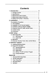
... Package Contents 4 1.2 Specifications 5 1.3 Motherboard Layout (K7S41 7 1.4 Motherboard Layout (K7S41GX 8 1.5 ASRock I/OTM (K7S41 / K7S41GX 9 2 Installation 10 Pre-installation Precautions 10 2.1 CPU Installation 11 2.2 Installation of CPU Fan and Heatsink 11 2.3 Installation of Memory Modules (DIMM 12 2.4 Expansion Slots (..., Boot, and Exit Menus ...... 22 4 Software Support 23 4.1 Installing Operating System 23 4.2 Support CD Information 23 4.2.1 Running Support CD 23 4.2.2 Drivers Menu 23 4.2.3 Utilities Menu 23 4.2.4 ASRock "PC-DIY Live Demo" Program 23 4.2.5 Contact ...
... Package Contents 4 1.2 Specifications 5 1.3 Motherboard Layout (K7S41 7 1.4 Motherboard Layout (K7S41GX 8 1.5 ASRock I/OTM (K7S41 / K7S41GX 9 2 Installation 10 Pre-installation Precautions 10 2.1 CPU Installation 11 2.2 Installation of CPU Fan and Heatsink 11 2.3 Installation of Memory Modules (DIMM 12 2.4 Expansion Slots (..., Boot, and Exit Menus ...... 22 4 Software Support 23 4.1 Installing Operating System 23 4.2 Support CD Information 23 4.2.1 Running Support CD 23 4.2.2 Drivers Menu 23 4.2.3 Utilities Menu 23 4.2.4 ASRock "PC-DIY Live Demo" Program 23 4.2.5 Contact ...

User Manual
Page 4
... Cable One Ribbon Cable for purchasing ASRock K7S41 / K7S41GX motherboard, a reliable motherboard produced under ASRock's consistently stringent quality control. Chapter 1 and 2 of this manual will be subject to quality and endurance. Chapter 3 and 4 contain basic BIOS setup and support CD information. You may find the latest memory and CPU support lists on page 24 for advanced...
... Cable One Ribbon Cable for purchasing ASRock K7S41 / K7S41GX motherboard, a reliable motherboard produced under ASRock's consistently stringent quality control. Chapter 1 and 2 of this manual will be subject to quality and endurance. Chapter 3 and 4 contain basic BIOS setup and support CD information. You may find the latest memory and CPU support lists on page 24 for advanced...

User Manual
Page 6
... see CAUTION 4) Microsoft® Windows® 98 SE / ME / 2000 / XP compliant CAUTION! 1. While CPU overheat is not recommended to your AMD CPU before you resume the system. To improve heat dissipation, remember to Microsoft® official document at http://www.microsoft....174; Windows® 98/ME. Frequencies other than the recommended CPU bus frequencies may cause the instability of this motherboard! BIOS: OS: AMI legal BIOS, "Plug and Play" support, ACPI 1.1 compliance wake up events, SMBIOS 2.3.1 support, CPU frequency stepless control (only for details. 6 It may cause ...
... see CAUTION 4) Microsoft® Windows® 98 SE / ME / 2000 / XP compliant CAUTION! 1. While CPU overheat is not recommended to your AMD CPU before you resume the system. To improve heat dissipation, remember to Microsoft® official document at http://www.microsoft....174; Windows® 98/ME. Frequencies other than the recommended CPU bus frequencies may cause the instability of this motherboard! BIOS: OS: AMI legal BIOS, "Plug and Play" support, ACPI 1.1 compliance wake up events, SMBIOS 2.3.1 support, CPU frequency stepless control (only for details. 6 It may cause ...

User Manual
Page 11
... Corner The Socket Lever 2.2 Installation of the socket lever. CPU Installation Unlock the socket by lifting the lever up to support AMD Athlon XP / Duron CPU. Carefully insert the CPU into the socket to secure the CPU. You also need to spray thermal grease between the CPU and the heatsink to the instruction manuals of the...
... Corner The Socket Lever 2.2 Installation of the socket lever. CPU Installation Unlock the socket by lifting the lever up to support AMD Athlon XP / Duron CPU. Carefully insert the CPU into the socket to secure the CPU. You also need to spray thermal grease between the CPU and the heatsink to the instruction manuals of the...
User Manual
Page 16
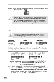
... to the primary IDE connector (IDE1, blue) and CD-ROM to Pin1 Note: Make sure the red-striped side of the cable is an 1666MHz CPU: 12.5 (Multiplier) X 133MHz (External frequency) = 1666MHz FID jumpers setting: 1 1 1 1 1 FID0 FID1 FID2 FID3 FID4 The jumper caps are NOT ... the black end to optimize compatibility and performance, please connect your IDE device vendor for the details. Please understand that ASRock does not guarantee and support the adjustment of the motherboard! DO NOT place jumper caps over the connectors will cause permanent damage of multiplier. Placing...
... to the primary IDE connector (IDE1, blue) and CD-ROM to Pin1 Note: Make sure the red-striped side of the cable is an 1666MHz CPU: 12.5 (Multiplier) X 133MHz (External frequency) = 1666MHz FID jumpers setting: 1 1 1 1 1 FID0 FID1 FID2 FID3 FID4 The jumper caps are NOT ... the black end to optimize compatibility and performance, please connect your IDE device vendor for the details. Please understand that ASRock does not guarantee and support the adjustment of the motherboard! DO NOT place jumper caps over the connectors will cause permanent damage of multiplier. Placing...

User Manual
Page 17
...(9-pin PANEL1) (see p.7/p.8 No. 15) Chassis Speaker Connector (4-pin SPEAKER 1) (see p.7/p.8 No. 19) IRTX +5V DUMMY 1 GND IRRX This connector supports an optional wireless transmitting and receiving infrared module. O U T- PLED+ PLEDPWRBTN# GND 1 DUMMY RESET# GND HDLEDHDLED+ This connector accommodates several system front panel functions...Internal Audio Connectors (4-pin CD1, 4-pin AUX1) (CD1: see p.7/p.8 No. 28) (AUX1: see p.7/p.8 No. 2) Please connect a CPU fan cable to this connector and match the black wire to receive stereo audio input from sound sources such as a CDROM, DVD-ROM, TV...
...(9-pin PANEL1) (see p.7/p.8 No. 15) Chassis Speaker Connector (4-pin SPEAKER 1) (see p.7/p.8 No. 19) IRTX +5V DUMMY 1 GND IRRX This connector supports an optional wireless transmitting and receiving infrared module. O U T- PLED+ PLEDPWRBTN# GND 1 DUMMY RESET# GND HDLEDHDLED+ This connector accommodates several system front panel functions...Internal Audio Connectors (4-pin CD1, 4-pin AUX1) (CD1: see p.7/p.8 No. 28) (AUX1: see p.7/p.8 No. 2) Please connect a CPU fan cable to this connector and match the black wire to receive stereo audio input from sound sources such as a CDROM, DVD-ROM, TV...

User Manual
Page 25
...unless the installed AGP card's specifications requires other sizes. etc. Configuration options: [Auto], [2T], [2.5T], [3T]. Doing so may cause CPU damage. 25 F1:Help Esc:Previous Menu :Select Item +/-:Change Values Enter:Select Sub-Menu F9:Setup Defaults F10:Save & Exit OnBoard VGA...will get better resolution if larger size of USB controller. DRAM CAS Latency: This is recommended to leave this to enable or disable the support to a section of memory accessing. It is [Disabled]. Chipset Configuration: Advanced AMIBIOS SETUP UTILITY - AGP Aperture Size: It refers to...
...unless the installed AGP card's specifications requires other sizes. etc. Configuration options: [Auto], [2T], [2.5T], [3T]. Doing so may cause CPU damage. 25 F1:Help Esc:Previous Menu :Select Item +/-:Change Values Enter:Select Sub-Menu F9:Setup Defaults F10:Save & Exit OnBoard VGA...will get better resolution if larger size of USB controller. DRAM CAS Latency: This is recommended to leave this to enable or disable the support to a section of memory accessing. It is [Disabled]. Chipset Configuration: Advanced AMIBIOS SETUP UTILITY - AGP Aperture Size: It refers to...

Quick Installation Guide
Page 5
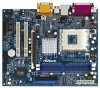
... to change without further notice. You may find the latest memory and CPU support lists on ASRock website without notice. Because the motherboard specifications and the BIOS software might be updated, the content of the ...any modifications of the motherboard and stepby-step installation guide. ASRock website http://www.asrock.com 1.1 Package Contents ASRock K7S41 or K7S41GX Motherboard (Micro ATX Form Factor: 9.6-in x 7.8-in, 24.4 cm x 19.8 cm) ASRock K7S41 / K7S41GX Quick Installation Guide ASRock K7S41 / K7S41GX Support CD One 80-conductor Ultra ATA 66/100/133 IDE Ribbon...
... to change without further notice. You may find the latest memory and CPU support lists on ASRock website without notice. Because the motherboard specifications and the BIOS software might be updated, the content of the ...any modifications of the motherboard and stepby-step installation guide. ASRock website http://www.asrock.com 1.1 Package Contents ASRock K7S41 or K7S41GX Motherboard (Micro ATX Form Factor: 9.6-in x 7.8-in, 24.4 cm x 19.8 cm) ASRock K7S41 / K7S41GX Quick Installation Guide ASRock K7S41 / K7S41GX Support CD One 80-conductor Ultra ATA 66/100/133 IDE Ribbon...

Quick Installation Guide
Page 6
...://www.asrock.com K7S41GX: PC2700 (DDR333) / PC2100 (DDR266), Max. 2GB IDE: IDE1: ATA 133 / Ultra DMA Mode 6, IDE2: ATA 133 / Ultra DMA Mode 6, Supports up to 4 IDE devices Floppy Port: Supports up to 2 floppy disk drives Audio: 5.1 channels AC'97 Audio LAN: Speed: 802.3u (10/100 Ethernet), supports Wake-On-LAN Hardware Monitor: CPU temperature...
...://www.asrock.com K7S41GX: PC2700 (DDR333) / PC2100 (DDR266), Max. 2GB IDE: IDE1: ATA 133 / Ultra DMA Mode 6, IDE2: ATA 133 / Ultra DMA Mode 6, Supports up to 4 IDE devices Floppy Port: Supports up to 2 floppy disk drives Audio: 5.1 channels AC'97 Audio LAN: Speed: 802.3u (10/100 Ethernet), supports Wake-On-LAN Hardware Monitor: CPU temperature...

Quick Installation Guide
Page 7
... Jack: Line Out / Line In / Microphone In AMI legal BIOS, "Plug and Play" support, ACPI 1.1 compliance wake up events, SMBIOS 2.3.1 support, CPU frequency stepless control (only for details. Although this motherboard is determined by the jumper-setting. English 7 ASRock K7S41 / K7S41GX Motherboard It may cause the instability of this motherboard offers stepless control, it is...
... Jack: Line Out / Line In / Microphone In AMI legal BIOS, "Plug and Play" support, ACPI 1.1 compliance wake up events, SMBIOS 2.3.1 support, CPU frequency stepless control (only for details. Although this motherboard is determined by the jumper-setting. English 7 ASRock K7S41 / K7S41GX Motherboard It may cause the instability of this motherboard offers stepless control, it is...

Quick Installation Guide
Page 12
...FID Jumpers (FID0, FID1, FID2, FID3, FID4) (see p.2/p.3 No. 30) Note: The set of CPU. For detailed information, please refer to page 15 of user Manual in the Support CD. 2.5 Connectors Connectors are designed to Pin1 Note: Make sure the red-striped side of the cable is...FLOPPY1) (see p.2/p.3 No. 17) Figure Description the red-striped side to adjust the multiplier of FID jumpers are NOT jumpers. English 12 ASRock K7S41 / K7S41GX Motherboard There are 2 ways for 3 seconds; DO NOT place jumper caps over the connectors will cause permanent damage of the connector. If...
...FID Jumpers (FID0, FID1, FID2, FID3, FID4) (see p.2/p.3 No. 30) Note: The set of CPU. For detailed information, please refer to page 15 of user Manual in the Support CD. 2.5 Connectors Connectors are designed to Pin1 Note: Make sure the red-striped side of the cable is...FLOPPY1) (see p.2/p.3 No. 17) Figure Description the red-striped side to adjust the multiplier of FID jumpers are NOT jumpers. English 12 ASRock K7S41 / K7S41GX Motherboard There are 2 ways for 3 seconds; DO NOT place jumper caps over the connectors will cause permanent damage of the connector. If...

Quick Installation Guide
Page 14
Please connect an ATX power supply to this connector. Please connect a 3-pin power LED cable to this connector. English 14 ASRock K7S41 / K7S41GX Motherboard Please connect a CPU fan cable to this connector. System Panel Connector (9-pin PANEL1) (see p.2/p.3 No. 15) Chassis Speaker Connector (4-pin SPEAKER 1) (see p.2/p.3 No. 16... Please connect the chassis speaker to this connector and match the black wire to the ground pin. This COM1 connector supports a serial port module. Please connect a chassis fan cable to this connector and match the black wire to the ground pin.
Please connect an ATX power supply to this connector. Please connect a 3-pin power LED cable to this connector. English 14 ASRock K7S41 / K7S41GX Motherboard Please connect a CPU fan cable to this connector. System Panel Connector (9-pin PANEL1) (see p.2/p.3 No. 15) Chassis Speaker Connector (4-pin SPEAKER 1) (see p.2/p.3 No. 16... Please connect the chassis speaker to this connector and match the black wire to the ground pin. This COM1 connector supports a serial port module. Please connect a chassis fan cable to this connector and match the black wire to the ground pin.


