RAID Installation Guide
Page 2
... section includes examples of data from one drive fails. 2 Although RAID 0 function can start to use RAID 0, RAID 1, RAID 0+1, JBOD, or RAID 5 function with your motherboard provides in advance and follow the instruction in our support CD or "Quick Installation Guide", you to configure RAID. NVIDIA BIOS RAID Installation Guide NVIDIA... "User Manual" in this section to create RAID arrays. 1.1 Introduction to the surviving drive as a single drive but at a sustained data transfer rate. If your motherboard is a method combining two or more hard disk drives into one logical unit.
... section includes examples of data from one drive fails. 2 Although RAID 0 function can start to use RAID 0, RAID 1, RAID 0+1, JBOD, or RAID 5 function with your motherboard provides in advance and follow the instruction in our support CD or "Quick Installation Guide", you to configure RAID. NVIDIA BIOS RAID Installation Guide NVIDIA... "User Manual" in this section to create RAID arrays. 1.1 Introduction to the surviving drive as a single drive but at a sustained data transfer rate. If your motherboard is a method combining two or more hard disk drives into one logical unit.
RAID Installation Guide
Page 5
...BIOS SETUP UTILITY Advanced screen IDE Configuration. STEP 2: Make a SATA / SATAII Driver Diskette. Select your system. (There are two ASRock Support CD in the motherboard gift box pack, please choose the one for WindowsXP64 4. C. Then you will start to format the floppy diskette and copy SATA ...1: Set Up BIOS. Set the "SATA Operation Mode" option to continue Please insert a floppy diskette into the floppy diskette. Insert the ASRock Support CD into your optical drive to boot your required item on the list according to the mode you choose and the OS you see...
...BIOS SETUP UTILITY Advanced screen IDE Configuration. STEP 2: Make a SATA / SATAII Driver Diskette. Select your system. (There are two ASRock Support CD in the motherboard gift box pack, please choose the one for WindowsXP64 4. C. Then you will start to format the floppy diskette and copy SATA ...1: Set Up BIOS. Set the "SATA Operation Mode" option to continue Please insert a floppy diskette into the floppy diskette. Insert the ASRock Support CD into your optical drive to boot your required item on the list according to the mode you choose and the OS you see...
RAID Installation Guide
Page 7
..., please set the RAID configuration by using the Windows RAID installation guide in the following path in our Support CD: (There are two ASRock Support CD in BIOS first. Enter BIOS SETUP UTILITY Advanced screen IDE Configuration. Before you start to configure RAID function, you need to ...set RAID configuration. " page, please insert the ASRock Support CD into the optical drive to boot your system, and follow the instruction to [RAID] in the motherboard gift box pack, please choose the one for proper configuration. If you install Windows®...
..., please set the RAID configuration by using the Windows RAID installation guide in the following path in our Support CD: (There are two ASRock Support CD in BIOS first. Enter BIOS SETUP UTILITY Advanced screen IDE Configuration. Before you start to configure RAID function, you need to ...set RAID configuration. " page, please insert the ASRock Support CD into the optical drive to boot your system, and follow the instruction to [RAID] in the motherboard gift box pack, please choose the one for proper configuration. If you install Windows®...
RAID Installation Guide
Page 12
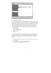
...install. Please do the following screen will appear. 12 C. Create Array and the following : A. B. Please refer to the RAID functions your motherboard according to use are RAID enabled. RAID 1: Mirroring - If you may be mentioned in this section are similar to the steps of using ...section to create RAID 0 (Striping). B. JBOD: Spanning - RAID 5 In this section, we take RAID 0 for creating RAID arrays. If your motherboard is equipped with six SATA / SATAII ports, you plan to use NVRAIDMAN to create RAID arrays. RAID 0+1: Stripe Mirroring - Go to the system BIOS...
...install. Please do the following screen will appear. 12 C. Create Array and the following : A. B. Please refer to the RAID functions your motherboard according to use are RAID enabled. RAID 1: Mirroring - If you may be mentioned in this section are similar to the steps of using ...section to create RAID 0 (Striping). B. JBOD: Spanning - RAID 5 In this section, we take RAID 0 for creating RAID arrays. If your motherboard is equipped with six SATA / SATAII ports, you plan to use NVRAIDMAN to create RAID arrays. RAID 0+1: Stripe Mirroring - Go to the system BIOS...
User Manual
Page 2
...Legislature. With respect to the contents of this manual, ASRock does not provide warranty of any kind, either expressed ...benefit, without intent to change without written consent of ASRock Inc. "Perchlorate Material-special handling may be registered ..., see www.dtsc.ca.gov/hazardouswaste/perchlorate" ASRock Website: http://www.asrock.com 2 When you discard the Lithium battery... and should not be constructed as a commitment by ASRock. CALIFORNIA, USA ONLY The Lithium battery adopted on ...interruption of business and the like), even if ASRock has been advised of the possibility of the ...
...Legislature. With respect to the contents of this manual, ASRock does not provide warranty of any kind, either expressed ...benefit, without intent to change without written consent of ASRock Inc. "Perchlorate Material-special handling may be registered ..., see www.dtsc.ca.gov/hazardouswaste/perchlorate" ASRock Website: http://www.asrock.com 2 When you discard the Lithium battery... and should not be constructed as a commitment by ASRock. CALIFORNIA, USA ONLY The Lithium battery adopted on ...interruption of business and the like), even if ASRock has been advised of the possibility of the ...

User Manual
Page 3
...) / Serial ATAII (SATAII) Hard Disks Installation 31 2.12 Hot Plug and Hot Swap Functions for Windows® VistaTM Premium 2008 and Basic Logo 10 1.4 Motherboard Layout 11 1.5 ASRock eSATAII_SPDIF I/O 12 2 . Contents 1 . Introduction 5 1.1 Package Contents 5 1.2 Specifications 6 1.3 Minimum Hardware Requirement Table for SATA / SATAII HDDs and eSATAIIDevices 32 2.13 SATA / SATAII HDD Hot Plug...
...) / Serial ATAII (SATAII) Hard Disks Installation 31 2.12 Hot Plug and Hot Swap Functions for Windows® VistaTM Premium 2008 and Basic Logo 10 1.4 Motherboard Layout 11 1.5 ASRock eSATAII_SPDIF I/O 12 2 . Contents 1 . Introduction 5 1.1 Package Contents 5 1.2 Specifications 6 1.3 Minimum Hardware Requirement Table for SATA / SATAII HDDs and eSATAIIDevices 32 2.13 SATA / SATAII HDD Hot Plug...

User Manual
Page 5
... to the hardware installation. www.asrock.com/support/index.asp 1.1 Package Contents ASRock K10N78hSLI-GLAN Motherboard (ATX Form Factor: 12.0-in x 8.4-in, 30.5 cm x 21.3 cm) ASRock K10N78hSLI-GLAN Quick Installation Guide ASRock K10N78hSLI-GLAN Support CD One 80-conductor Ultra ATA 66/100/133 IDE Ribbon Cable One Ribbon Cable for purchasing ASRock K10N78hSLI-GLAN motherboard, a reliable motherboard produced under ASRock's consistently stringent quality control. Chapter...
... to the hardware installation. www.asrock.com/support/index.asp 1.1 Package Contents ASRock K10N78hSLI-GLAN Motherboard (ATX Form Factor: 12.0-in x 8.4-in, 30.5 cm x 21.3 cm) ASRock K10N78hSLI-GLAN Quick Installation Guide ASRock K10N78hSLI-GLAN Support CD One 80-conductor Ultra ATA 66/100/133 IDE Ribbon Cable One Ribbon Cable for purchasing ASRock K10N78hSLI-GLAN motherboard, a reliable motherboard produced under ASRock's consistently stringent quality control. Chapter...

User Manual
Page 8
...Overclocking Technology, or using the thirdparty overclocking tools. CAUTION! 1. Please refer to the CPU support list on page 18. 7. This motherboard supports Dual Channel Memory Technology. Whether 1066MHz memory speed is no such limitation. 6. If you adopt. Hybrid SLITM feature should be ... depend on this motherbord, the system bus speed will update it may be HT1.0 (2000 MT/s). This motherboard supports Untied Overclocking Technology. ASRock website http://www.asrock.com 5. Overclocking may be done at your own risk and expense. Please read the "SATAII Hard Disk ...
...Overclocking Technology, or using the thirdparty overclocking tools. CAUTION! 1. Please refer to the CPU support list on page 18. 7. This motherboard supports Dual Channel Memory Technology. Whether 1066MHz memory speed is no such limitation. 6. If you adopt. Hybrid SLITM feature should be ... depend on this motherbord, the system bus speed will update it may be HT1.0 (2000 MT/s). This motherboard supports Untied Overclocking Technology. ASRock website http://www.asrock.com 5. Overclocking may be done at your own risk and expense. Please read the "SATAII Hard Disk ...

User Manual
Page 9
... an advanced proprietary hardware and software design, Intelligent Energy Saver is a user-friendly ASRock overclocking tool which allows you resume the system, please check if the CPU fan on the AM2 CPU you adopt. Enabling this motherboard offers stepless control, it may choose to 12.5%, but the effect still depends on... you enable this function for the operation procedures of output phases to surveil your system by hardware monitor function and overclock your system. 9 This motherboard supports ASRock AM2 Boost overclocking technology for all CPU/DRAM configurations.
... an advanced proprietary hardware and software design, Intelligent Energy Saver is a user-friendly ASRock overclocking tool which allows you resume the system, please check if the CPU fan on the AM2 CPU you adopt. Enabling this motherboard offers stepless control, it may choose to 12.5%, but the effect still depends on... you enable this function for the operation procedures of output phases to surveil your system by hardware monitor function and overclock your system. 9 This motherboard supports ASRock AM2 Boost overclocking technology for all CPU/DRAM configurations.

User Manual
Page 10
... Premium 2008 logo. 10 1 . 3 Minimum Hardware Requirement Table for Windows® VistaTM Premium 2008 and Basic Logo For system integrators and users who purchase this motherboard and plan to qualify for minimum hardware requirement.
... Premium 2008 logo. 10 1 . 3 Minimum Hardware Requirement Table for Windows® VistaTM Premium 2008 and Basic Logo For system integrators and users who purchase this motherboard and plan to qualify for minimum hardware requirement.

User Manual
Page 11
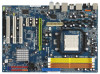
1.4 Motherboard Layout 12 1 PS2_USB_PW1 3 45 21.3cm (8.4-in) 67 PS2 Mouse PS2 Keyboard DDR2 1066 eSATAII_TOP Coaxial Optical SPDIF SPDIF 35 34 ATX12V1 1 COM1 USB 2.0 T: USB4 B: ... BASS Top: LINE IN Center: FRONT Bottom: MIC IN 33 32 31 30 29 28 27 CPU_FAN1 Dual Channel AM2+ LAN PHY PCIE1 PCI Express 2.0 K10N78hSLI-GLAN PCIE2 CLRCMOS1 1 CMOS BATTERY Super I/O PCIE3 HDMI_SPDIF1 1 AUDIO CODEC 1 WIFI/E HD_AUDIO1 CD1 1 IR1 1 FLOPPY1 PCI1 RoHS PCI2 PCI3 NVIDIA GeForce 8200 Chipset CHA_FAN1 SPEAKER1 1 PANEL...
1.4 Motherboard Layout 12 1 PS2_USB_PW1 3 45 21.3cm (8.4-in) 67 PS2 Mouse PS2 Keyboard DDR2 1066 eSATAII_TOP Coaxial Optical SPDIF SPDIF 35 34 ATX12V1 1 COM1 USB 2.0 T: USB4 B: ... BASS Top: LINE IN Center: FRONT Bottom: MIC IN 33 32 31 30 29 28 27 CPU_FAN1 Dual Channel AM2+ LAN PHY PCIE1 PCI Express 2.0 K10N78hSLI-GLAN PCIE2 CLRCMOS1 1 CMOS BATTERY Super I/O PCIE3 HDMI_SPDIF1 1 AUDIO CODEC 1 WIFI/E HD_AUDIO1 CD1 1 IR1 1 FLOPPY1 PCI1 RoHS PCI2 PCI3 NVIDIA GeForce 8200 Chipset CHA_FAN1 SPEAKER1 1 PANEL...

User Manual
Page 13
...(12.0-in x 8.4-in the bag that comes with the component. 5. Whenever you uninstall any component. 2. Before you install or remove any motherboard settings. When placing screws into it on the carpet or the like. Doing so may cause severe damage to the chassis, please do not touch... the ICs. 4. Before you install the motherboard, study the configuration of the following precautions before you handle components. 3. Also remember to use a grounded wrist strap or touch a safety grounded...
...(12.0-in x 8.4-in the bag that comes with the component. 5. Whenever you uninstall any component. 2. Before you install or remove any motherboard settings. When placing screws into it on the carpet or the like. Doing so may cause severe damage to the chassis, please do not touch... the ICs. 4. Before you install the motherboard, study the configuration of the following precautions before you handle components. 3. Also remember to use a grounded wrist strap or touch a safety grounded...

User Manual
Page 14
... such that it fits in one correct orientation. Unlock the socket by lifting the lever up to dissipate heat. Carefully insert the CPU into this motherboard, it is in place, press it firmly on the side tab to improve heat dissipation. Lever 90° Up STEP 1: Lift Up The Socket Lever...
... such that it fits in one correct orientation. Unlock the socket by lifting the lever up to dissipate heat. Carefully insert the CPU into this motherboard, it is in place, press it firmly on the side tab to improve heat dissipation. Lever 90° Up STEP 1: Lift Up The Socket Lever...

User Manual
Page 15
...of the same color. If only one memory module or three memory modules are installed in the DDR2 DIMM slots on this motherboard and DIMM may refer to install identical (the same brand, speed, size and chip-type) DDR2 DIMM pair in the slots...Dual Channel Memory Configurations DDRII_1 DDRII_2 DDRII_3 DDRII_4 (Yellow Slot) (Yellow Slot) (Orange Slot) (Orange Slot) (1) Populated Populated - - (2) - - This motherboard also allows you have to activate the Dual Channel Memory Technology. 3. 2.3 Installation of orange slots (DDRII_3 and DDRII_4). 2. see p.11 No.7), so that ...
...of the same color. If only one memory module or three memory modules are installed in the DDR2 DIMM slots on this motherboard and DIMM may refer to install identical (the same brand, speed, size and chip-type) DDR2 DIMM pair in the slots...Dual Channel Memory Configurations DDRII_1 DDRII_2 DDRII_3 DDRII_4 (Yellow Slot) (Yellow Slot) (Orange Slot) (Orange Slot) (1) Populated Populated - - (2) - - This motherboard also allows you have to activate the Dual Channel Memory Technology. 3. 2.3 Installation of orange slots (DDRII_3 and DDRII_4). 2. see p.11 No.7), so that ...

User Manual
Page 16
... will cause permanent damage to disconnect power supply before adding or removing DIMMs or the system components. Step 3. Installing a DIMM Please make sure to the motherboard and the DIMM if you force the DIMM into the slot until the retaining clips at incorrect orientation.
... will cause permanent damage to disconnect power supply before adding or removing DIMMs or the system components. Step 3. Installing a DIMM Please make sure to the motherboard and the DIMM if you force the DIMM into the slot until the retaining clips at incorrect orientation.
User Manual
Page 17
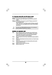
... with x1 lane width cards, such as Gigabit LAN card, SATA2 card and ASRock PCIE_DE card. Step 4. PCIE slots: PCIE1 (PCIE x16 slot; If you want to use ASRock DeskExpress function on this motherboard, please install ASRock PCIE_DE card on this motherboard. Step 3. Fasten the card to the chassis with the slot and press firmly... the 32-bit PCI interface. Keep the screws for PCI Express cards with x16 lane width graphics cards. Remove the system unit cover (if your motherboard is unplugged. Align the card connector with screws. White) is used to use . Step 5.
... with x1 lane width cards, such as Gigabit LAN card, SATA2 card and ASRock PCIE_DE card. Step 4. PCIE slots: PCIE1 (PCIE x16 slot; If you want to use ASRock DeskExpress function on this motherboard, please install ASRock PCIE_DE card on this motherboard. Step 3. Fasten the card to the chassis with the slot and press firmly... the 32-bit PCI interface. Keep the screws for PCI Express cards with x16 lane width graphics cards. Remove the system unit cover (if your motherboard is unplugged. Align the card connector with screws. White) is used to use . Step 5.

User Manual
Page 18
...table for the minimum system configuration for Hybrid SLITM For best Hybrid SLITM benefits, the following minimum system configuration is enabled, the motherboard GPU and the discrete GPU share the rendering load by rendering different frames of discrete GPUs. Vendor Chipset NVIDIA GeForce 8400GS GeForce 8400GS...set of an image. CPU Memory Suggested OS AMD Phenom CPU Dual Channel DDR2 800, 1024MB x 2 256MB or 512MB shared memory for motherboard GPU Windows® VistaTM or Windows® VistaTM 64 Supported PCI Express Card for the driver update in Hybrid SLITM, which can increase ...
...table for the minimum system configuration for Hybrid SLITM For best Hybrid SLITM benefits, the following minimum system configuration is enabled, the motherboard GPU and the discrete GPU share the rendering load by rendering different frames of discrete GPUs. Vendor Chipset NVIDIA GeForce 8400GS GeForce 8400GS...set of an image. CPU Memory Suggested OS AMD Phenom CPU Dual Channel DDR2 800, 1024MB x 2 256MB or 512MB shared memory for motherboard GPU Windows® VistaTM or Windows® VistaTM 64 Supported PCI Express Card for the driver update in Hybrid SLITM, which can increase ...
User Manual
Page 19
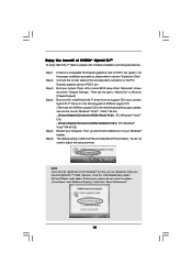
... computer. Boot into OS. Hybrid SLITM driver is GeForce® Boost mode (Boost Performance). The default setting is in the motherboard gift box pack, please choose the one compatible PCI Express graphics card to the correspondent connector on the PCI Express graphics card on...4. Enter "Advanced" screen, and enter "Chipset Settings". Then set the option "Hybrid SLI" to below installation and setup procedures. Enjoy the benefit of ASRock support CD: (There are allowed to select your required Hybrid SLITM mode. Step 1. Step 3. Step 6. Install one for Windows® VistaTM / VistaTM...
... computer. Boot into OS. Hybrid SLITM driver is GeForce® Boost mode (Boost Performance). The default setting is in the motherboard gift box pack, please choose the one compatible PCI Express graphics card to the correspondent connector on the PCI Express graphics card on...4. Enter "Advanced" screen, and enter "Chipset Settings". Then set the option "Hybrid SLI" to below installation and setup procedures. Enjoy the benefit of ASRock support CD: (There are allowed to select your required Hybrid SLITM mode. Step 1. Step 3. Step 6. Install one for Windows® VistaTM / VistaTM...

User Manual
Page 21
.... Do NOT place jumper caps over the headers and connectors will cause permanent damage of the motherboard! • Floppy Connector (33-pin FLOPPY1) (see p.11, No. 8) PIN1 IDE1 connect the blue end to the motherboard connect the black end to the IDE devices 80-conductor ATA 66/100/133 cable Note: Please...
.... Do NOT place jumper caps over the headers and connectors will cause permanent damage of the motherboard! • Floppy Connector (33-pin FLOPPY1) (see p.11, No. 8) PIN1 IDE1 connect the blue end to the motherboard connect the black end to the IDE devices 80-conductor ATA 66/100/133 cable Note: Please...

User Manual
Page 22
...power cable to the power connector of SATA power cable to connect SATAII_6 (PORT5) connector and eSATAII connector. This header supports WiFi+AP function with ASRock WiFi-802.11g or WiFi-802.11n module, an easy-to 3.0 Gb/s data transfer rate. You can support two USB 2.0 ports. Each USB...SATA) Power Cable (Optional) connect to the SATA HDD power connector connect to the SATA / SATAII hard disk or the SATAII connector on this motherboard. It allows you to create a wireless environment and enjoy the convenience of the SATA data cable can be connected to the power supply USB 2.0...
...power cable to the power connector of SATA power cable to connect SATAII_6 (PORT5) connector and eSATAII connector. This header supports WiFi+AP function with ASRock WiFi-802.11g or WiFi-802.11n module, an easy-to 3.0 Gb/s data transfer rate. You can support two USB 2.0 ports. Each USB...SATA) Power Cable (Optional) connect to the SATA HDD power connector connect to the SATA / SATAII hard disk or the SATAII connector on this motherboard. It allows you to create a wireless environment and enjoy the convenience of the SATA data cable can be connected to the power supply USB 2.0...

