
User Manual
Page 3
Contents 1 Introduction 5 1.1 Package Contents 5 1.2 Specifications 6 1.3 Motherboard Layout 12 1.4 I/O Panel 13 2 Installation 14 2.1 Screw Holes 14 2.2 Pre-installation Precautions 14 2.3 CPU Installation 15 2.4 Installation of Heatsink and CPU fan 17 2.5 Installation of Memory Modules (DIMM 18 2.6 Expansion Slots (PCI Express Slots 19 2.7 Dual Monitor and Surround Display Features 20 2.8 Jumpers Setup 23...
Contents 1 Introduction 5 1.1 Package Contents 5 1.2 Specifications 6 1.3 Motherboard Layout 12 1.4 I/O Panel 13 2 Installation 14 2.1 Screw Holes 14 2.2 Pre-installation Precautions 14 2.3 CPU Installation 15 2.4 Installation of Heatsink and CPU fan 17 2.5 Installation of Memory Modules (DIMM 18 2.6 Expansion Slots (PCI Express Slots 19 2.7 Dual Monitor and Surround Display Features 20 2.8 Jumpers Setup 23...

User Manual
Page 4
3 UEFI SETUP UTILITY 33 3.1 Introduction 33 3.1.1 UEFI Menu Bar 33 3.1.2 Navigation Keys 34 3.2 Main Screen 34 3.3 OC Tweaker Screen 35 3.4 Advanced Screen 40 3.4.1 CPU Configuration 41 3.4.2 North Bridge Configuration 42 3.4.3 South Bridge Configuration 43 3.4.4 Storage Configuration 44 3.4.5 Intel(R) Rapid Start Technology ...
3 UEFI SETUP UTILITY 33 3.1 Introduction 33 3.1.1 UEFI Menu Bar 33 3.1.2 Navigation Keys 34 3.2 Main Screen 34 3.3 OC Tweaker Screen 35 3.4 Advanced Screen 40 3.4.1 CPU Configuration 41 3.4.2 North Bridge Configuration 42 3.4.3 South Bridge Configuration 43 3.4.4 Storage Configuration 44 3.4.5 Intel(R) Rapid Start Technology ...
User Manual
Page 5
... further notice. www.asrock.com/support/index.asp 1.1 Package Contents ASRock H71M-DG3 Motherboard (Micro ATX Form Factor: 8.9-in x 6.8-in, 22.6 cm x 17.3 cm) ASRock H71M-DG3 Quick Installation Guide ASRock H71M-DG3 Support CD 2 x Serial ATA (SATA) Data Cables (Optional) 1 x I/O Panel Shield ASRock Reminds You... You may find the latest VGA cards and CPU support lists on ASRock website without notice.
... further notice. www.asrock.com/support/index.asp 1.1 Package Contents ASRock H71M-DG3 Motherboard (Micro ATX Form Factor: 8.9-in x 6.8-in, 22.6 cm x 17.3 cm) ASRock H71M-DG3 Quick Installation Guide ASRock H71M-DG3 Support CD 2 x Serial ATA (SATA) Data Cables (Optional) 1 x I/O Panel Shield ASRock Reminds You... You may find the latest VGA cards and CPU support lists on ASRock website without notice.

User Manual
Page 6
...3D, Intel® Clear Video HD Technology, Intel® HD Graphics 2000/3000, Intel® Advanced Vector Extensions (AVX) with Intel® Ivy Bridge CPU. Micro ATX Form Factor: 8.9-in x 6.8-in LGA1155 Package - Supports Hyper-Threading Technology (see CAUTION 3) - Supports Intel® HD Graphics Built-in... Visuals and the VGA outputs can be supported only with Intel® Ivy Bridge CPU - Max. Supports 3rd and 2nd Generation Intel® CoreTM i7 / i5 / i3 in , 22.6 cm x 17.3 cm - Supports Intel®...
...3D, Intel® Clear Video HD Technology, Intel® HD Graphics 2000/3000, Intel® Advanced Vector Extensions (AVX) with Intel® Ivy Bridge CPU. Micro ATX Form Factor: 8.9-in x 6.8-in LGA1155 Package - Supports Hyper-Threading Technology (see CAUTION 3) - Supports Intel® HD Graphics Built-in... Visuals and the VGA outputs can be supported only with Intel® Ivy Bridge CPU - Max. Supports 3rd and 2nd Generation Intel® CoreTM i7 / i5 / i3 in , 22.6 cm x 17.3 cm - Supports Intel®...

User Manual
Page 7
.../Power FAN connector - 24 pin ATX power connector - 4 pin 12V power connector - ACPI 1.1 Compliance Wake Up Events - IGPU, DRAM, PCH, CPU PLL, VTT, VCCSA Voltage Multi-adjustment 7 PCIE x1 Gigabit LAN 10/100/1000 Mb/s - HD Audio Jack: Line in/Front Speaker/Microphone - 4 x SATA2 3.0 Gb/s connectors, ...
.../Power FAN connector - 24 pin ATX power connector - 4 pin 12V power connector - ACPI 1.1 Compliance Wake Up Events - IGPU, DRAM, PCH, CPU PLL, VTT, VCCSA Voltage Multi-adjustment 7 PCIE x1 Gigabit LAN 10/100/1000 Mb/s - HD Audio Jack: Line in/Front Speaker/Microphone - 4 x SATA2 3.0 Gb/s connectors, ...

User Manual
Page 8
... Quiet Fan (Allow Chassis Fan Speed Auto-Adjust by overclocking. 8 We are not responsible for possible damage caused by CPU Temperature) - OEM Unique Feature - Hybrid Booster: - ASRock U-COP (see CAUTION 7) - Chassis Temperature Sensing - CPU/Chassis Fan Multi-Speed Control - Overclocking may affect your system stability, or even cause damage to the components and...
... Quiet Fan (Allow Chassis Fan Speed Auto-Adjust by overclocking. 8 We are not responsible for possible damage caused by CPU Temperature) - OEM Unique Feature - Hybrid Booster: - ASRock U-COP (see CAUTION 7) - Chassis Temperature Sensing - CPU/Chassis Fan Multi-Speed Control - Overclocking may affect your system stability, or even cause damage to the components and...

User Manual
Page 9
...reservation for the operation procedures of "Hyper Threading Technology", please check page 40. 2. Please check Intel® website for optimal system performance. ASRock Instant Flash is including Hardware Monitor, Fan Control, Overclocking, OC DNA and IES. With this tool and save your OC settings as a ...profile and share with 64-bit CPU, there is subject to access ASRock Instant Flash. ASRock Extreme Tuning Utility (AXTU) is an all-in a few clicks without entering operating systems first like MS-DOS...
...reservation for the operation procedures of "Hyper Threading Technology", please check page 40. 2. Please check Intel® website for optimal system performance. ASRock Instant Flash is including Hardware Monitor, Fan Control, Overclocking, OC DNA and IES. With this tool and save your OC settings as a ...profile and share with 64-bit CPU, there is subject to access ASRock Instant Flash. ASRock Extreme Tuning Utility (AXTU) is an all-in a few clicks without entering operating systems first like MS-DOS...

User Manual
Page 10
..., it also boosts the speed of internet browser, is that not all the 775 and 1156 CPU Fan can lower the latency in order to 40% faster than before. And it can be used . 10 ASRock APP Charger. Simply installing the APP Charger driver, it back again. SmartView, a new function ... which data streams you can easily recognize which includes below benefits. Real-Time Analysis of ASRock XFast RAM is the smart start page for IE that cannot be used under Windows® OS 32-bit CPU. Another advantage of Your Data: With the status window, you can easily enjoy the ...
..., it also boosts the speed of internet browser, is that not all the 775 and 1156 CPU Fan can lower the latency in order to 40% faster than before. And it can be used . 10 ASRock APP Charger. Simply installing the APP Charger driver, it back again. SmartView, a new function ... which data streams you can easily recognize which includes below benefits. Real-Time Analysis of ASRock XFast RAM is the smart start page for IE that cannot be used under Windows® OS 32-bit CPU. Another advantage of Your Data: With the status window, you can easily enjoy the ...

User Manual
Page 12
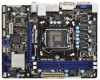
... 1 CHA_FAN1 8 COM1 USB6_7 PLED PWRBTN 1 1 1 HDLED RESET PANEL1 SATA2_2 SATA2_0 19 18 17 16 15 14 13 12 11 10 9 1 1155-Pin CPU Socket 2 ATX 12V Power Connector (ATX12V1) 3 CPU Fan Connector (CPU_FAN1) 4 ATX Power Connector (ATXPWR1) 5 2 x 240-pin DDR3 DIMM Slots (Dual Channel: DDR3_A1, DDR3_B1, Blue) 6 Intel H61 Chipset 7 32Mb SPI...
... 1 CHA_FAN1 8 COM1 USB6_7 PLED PWRBTN 1 1 1 HDLED RESET PANEL1 SATA2_2 SATA2_0 19 18 17 16 15 14 13 12 11 10 9 1 1155-Pin CPU Socket 2 ATX 12V Power Connector (ATX12V1) 3 CPU Fan Connector (CPU_FAN1) 4 ATX Power Connector (ATXPWR1) 5 2 x 240-pin DDR3 DIMM Slots (Dual Channel: DDR3_A1, DDR3_B1, Blue) 6 Intel H61 Chipset 7 32Mb SPI...

User Manual
Page 15
... cap. 2. This cap must be seriously damaged. Load Plate Load Lever Contact Array Socket Body 1155-Pin Socket Overview Before you insert the 1155-Pin CPU into the socket if above situation is recommended to use the cap tab to clear retention tab. Otherwise, the... CPU will be placed if returning the motherboard for after service. 15 Step 1-2. Rotate the load plate to fully open position at approximately 135 degrees. Step 1. ...
... cap. 2. This cap must be seriously damaged. Load Plate Load Lever Contact Array Socket Body 1155-Pin Socket Overview Before you insert the 1155-Pin CPU into the socket if above situation is recommended to use the cap tab to clear retention tab. Otherwise, the... CPU will be placed if returning the motherboard for after service. 15 Step 1-2. Rotate the load plate to fully open position at approximately 135 degrees. Step 1. ...

User Manual
Page 16
orientation key notch alignment key Pin1 Pin1 orientation key notch 1155-Pin CPU alignment key 1155-Pin Socket For proper inserting, please ensure to the orient keys. Step 4. Step 4-2. Insert the 1155-Pin CPU: Step 3-1. Step 3-3. black line Step 3-2. Locate Pin1 and the two orientation key notches.... the load plate onto the IHS. Hold the CPU by using a purely vertical motion. Verify that the CPU is marked with black line. While pressing down lightly on load plate, engage the load lever. 16 Carefully place the CPU into the socket by the edge where is within...
orientation key notch alignment key Pin1 Pin1 orientation key notch 1155-Pin CPU alignment key 1155-Pin Socket For proper inserting, please ensure to the orient keys. Step 4. Step 4-2. Insert the 1155-Pin CPU: Step 3-1. Step 3-3. black line Step 3-2. Locate Pin1 and the two orientation key notches.... the load plate onto the IHS. Hold the CPU by using a purely vertical motion. Verify that the CPU is marked with black line. While pressing down lightly on load plate, engage the load lever. 16 Carefully place the CPU into the socket by the edge where is within...

User Manual
Page 17
Ensure that this motherboard supports Combo Cooler Option (C.C.O.), which provides the flexible option to adopt three different CPU cooler types, Socket LGA 775, LGA 1155 and LGA 1156. Step 1. Apply Thermal Interface Material Step 2. Step 6. Please be secured on the ... on side closest to MB header Fastener slots pointing straight out Press Down (4 Places) If you need to spray thermal interface material between the CPU and the heatsink to dissipate heat. Step 4. Before you installed the heatsink, you press down on the motherboard. Ensure fan cables are for...
Ensure that this motherboard supports Combo Cooler Option (C.C.O.), which provides the flexible option to adopt three different CPU cooler types, Socket LGA 775, LGA 1155 and LGA 1156. Step 1. Apply Thermal Interface Material Step 2. Step 6. Please be secured on the ... on side closest to MB header Fastener slots pointing straight out Press Down (4 Places) If you need to spray thermal interface material between the CPU and the heatsink to dissipate heat. Step 4. Before you installed the heatsink, you press down on the motherboard. Ensure fan cables are for...

User Manual
Page 19
... facing the slot that the power supply is switched off or the power cord is already installed in Gen 3 speed, please install an Ivy Bridge CPU. 2.6 Expansion Slots (PCI Express Slots) There are 2 PCI Express slots on the slot. Only PCIE1 slot supports Gen 3 speed. Keep the ...screws for the card before you install a Sandy Bridge CPU, the PCI Express will run the PCI Express in a chassis). Replace the system cover. 19 Step 5. PCIE slots: PCIE1 (PCIE 3.0 x16 slot; Step ...
... facing the slot that the power supply is switched off or the power cord is already installed in Gen 3 speed, please install an Ivy Bridge CPU. 2.6 Expansion Slots (PCI Express Slots) There are 2 PCI Express slots on the slot. Only PCIE1 slot supports Gen 3 speed. Keep the ...screws for the card before you install a Sandy Bridge CPU, the PCI Express will run the PCI Express in a chassis). Replace the system cover. 19 Step 5. PCIE slots: PCIE1 (PCIE 3.0 x16 slot; Step ...

User Manual
Page 26
...1-3 Connected 3-Pin Fan Installation ATX Power Connector (24-pin ATXPWR1) (see p.12 No. 3) 4 3 2 1 GND +12V CPU_FAN_SPEED FAN_SPEED_CONTROL Please connect the CPU fan cable to the connector and match the black wire to Pin 1-3. When connecting your chassis front panel module to this header, make sure the... are matched correctly. A front panel module mainly consists of power switch, reset switch, power LED, hard drive activity LED, speaker and etc. CPU Fan Connectors (4-pin CPU_FAN1) (see p.12 No. 4) 12 24 Please connect an ATX power supply to this connector. 1 13 26 If ...
...1-3 Connected 3-Pin Fan Installation ATX Power Connector (24-pin ATXPWR1) (see p.12 No. 3) 4 3 2 1 GND +12V CPU_FAN_SPEED FAN_SPEED_CONTROL Please connect the CPU fan cable to the connector and match the black wire to Pin 1-3. When connecting your chassis front panel module to this header, make sure the... are matched correctly. A front panel module mainly consists of power switch, reset switch, power LED, hard drive activity LED, speaker and etc. CPU Fan Connectors (4-pin CPU_FAN1) (see p.12 No. 4) 12 24 Please connect an ATX power supply to this connector. 1 13 26 If ...

User Manual
Page 35
...Tweaker Screen In the OC Tweaker screen, you install Windows® VistaTM / 7 and want to enable this function, please set this function may reduce CPU voltage and lead to enable or disable Intel Turbo Boost Mode Technology. Processors can set up overclocking features. The default value is [Auto]. Turbo Boost... item to configure long duration power limit in specific conditions. The default value is Intel's new power saving technology. CPU Configuration CPU Turbo Ratio Use this item to [Disabled] if above issues occur. This item will be hidden if the current...
...Tweaker Screen In the OC Tweaker screen, you install Windows® VistaTM / 7 and want to enable this function, please set this function may reduce CPU voltage and lead to enable or disable Intel Turbo Boost Mode Technology. Processors can set up overclocking features. The default value is [Auto]. Turbo Boost... item to configure long duration power limit in specific conditions. The default value is Intel's new power saving technology. CPU Configuration CPU Turbo Ratio Use this item to [Disabled] if above issues occur. This item will be hidden if the current...

User Manual
Page 38
... voltage offset. Voltage Configuration Power Saving Mode Use this to your own requirements. 38 User Defaults In this to select CPU PLL Voltage. The default value is [Auto]. The default value is [Disabled]. The default value is [Auto]. VTT Voltage Use this option, you are ...allowed to load and save three user defaults according to enable or disable Power Saving Mode. CPU PLL Voltage Use this to select IGPU voltage offset. DRAM Voltage Use this to select VTT Voltage. IGPU Voltage Offset Use this to select PCH...
... voltage offset. Voltage Configuration Power Saving Mode Use this to your own requirements. 38 User Defaults In this to select CPU PLL Voltage. The default value is [Auto]. The default value is [Disabled]. The default value is [Auto]. VTT Voltage Use this option, you are ...allowed to load and save three user defaults according to enable or disable Power Saving Mode. CPU PLL Voltage Use this to select IGPU voltage offset. DRAM Voltage Use this to select VTT Voltage. IGPU Voltage Offset Use this to select PCH...

User Manual
Page 39
... your USB flash drive, floppy disk or hard drive and launch this section may set the configurations for the following items: CPU Configuration, North Bridge Configuration, South Bridge Configuration, Storage Configuration, Intel(R) Rapid Start Technology, Intel(R) Smart Connect Technology...
... your USB flash drive, floppy disk or hard drive and launch this section may set the configurations for the following items: CPU Configuration, North Bridge Configuration, South Bridge Configuration, Storage Configuration, Intel(R) Rapid Start Technology, Intel(R) Smart Connect Technology...

User Manual
Page 40
...system with an Intel processor that supports Hyper-Threading technology and an operating system that includes optimization for this to enable or disable CPU C3 (ACPI C2) report to OS. No-Execute Memory Protection No-Execution (NX) Memory Protection Technology is supported through the ...native processor instructions HLT and MWAIT and requires no hardware support from overheating. CPU C3 State Support Use this technology, such as Microsoft® Windows® XP / VistaTM / 7 is required. Set to [Enabled]...
...system with an Intel processor that supports Hyper-Threading technology and an operating system that includes optimization for this to enable or disable CPU C3 (ACPI C2) report to OS. No-Execute Memory Protection No-Execution (NX) Memory Protection Technology is supported through the ...native processor instructions HLT and MWAIT and requires no hardware support from overheating. CPU C3 State Support Use this technology, such as Microsoft® Windows® XP / VistaTM / 7 is required. Set to [Enabled]...

User Manual
Page 41
...a VMM (Virtual Machine Architecture) can prevent data pages from being used by Vanderpool Technology. This option will be hidden if the installed CPU does not support Intel Virtualization Technology. Adjacent Cache Line Prefetch Use this item to execute codes. This option will be hidden if the current... CPU does not support No-Excute Memory Protection. Hardware Prefetcher Use this item to the IA-32 Intel Architecture. to turn on /off...
...a VMM (Virtual Machine Architecture) can prevent data pages from being used by Vanderpool Technology. This option will be hidden if the installed CPU does not support Intel Virtualization Technology. Adjacent Cache Line Prefetch Use this item to execute codes. This option will be hidden if the current... CPU does not support No-Excute Memory Protection. Hardware Prefetcher Use this item to the IA-32 Intel Architecture. to turn on /off...

User Manual
Page 50
... On] and [Automatic Mode]. The default value is [Enabled]. 50 CPU Fan Setting This allows you to monitor the status of the hardware on your system, including the parameters of the CPU temperature, motherboard temperature, CPU fan speed, chassis fan speed, and the critical voltage. 3.5 Hardware... Health Event Monitoring Screen In this to set CPU fan's speed. The default value is [Full On]. Over Temperature...
... On] and [Automatic Mode]. The default value is [Enabled]. 50 CPU Fan Setting This allows you to monitor the status of the hardware on your system, including the parameters of the CPU temperature, motherboard temperature, CPU fan speed, chassis fan speed, and the critical voltage. 3.5 Hardware... Health Event Monitoring Screen In this to set CPU fan's speed. The default value is [Full On]. Over Temperature...


