
Intel Rapid Storage Guide
Page 16
... create a floppy disk with a screen asking you need to use the F6 installation method to install a RAID Note driver on your system, you can use a USB floppy drive or create a slipstream version of Windows XP* setup (during operating system installation. Note If you see a prompt that says, Press F6 if you...
... create a floppy disk with a screen asking you need to use the F6 installation method to install a RAID Note driver on your system, you can use a USB floppy drive or create a slipstream version of Windows XP* setup (during operating system installation. Note If you see a prompt that says, Press F6 if you...
User Manual
Page 4
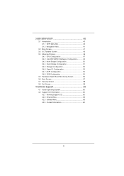
...figuration 50 3.4.4 South Bridge Configuration 51 3.4.5 Storage Configuration 52 3.4.6 Super IO Configuration 53 3.4.7 ACPI Configuration 54 3.4.8 USB Configuration 55 3.5 Hardware Health Event Monitoring Screen 56 3.6 Boot Screen 57 3.7 Security Screen 58 3.8 Exit Screen 59 4 Software Support 60 4.1 Install Operating System...
...figuration 50 3.4.4 South Bridge Configuration 51 3.4.5 Storage Configuration 52 3.4.6 Super IO Configuration 53 3.4.7 ACPI Configuration 54 3.4.8 USB Configuration 55 3.5 Hardware Health Event Monitoring Screen 56 3.6 Boot Screen 57 3.7 Security Screen 58 3.8 Exit Screen 59 4 Software Support 60 4.1 Install Operating System...
User Manual
Page 7
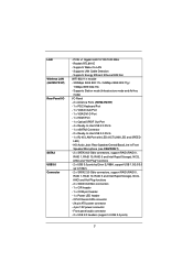
... - Realtek RTL8111E - CPU/Chassis FAN connector - 24 pin ATX power connector - 4 pin 12V power connector - Front panel audio connector - 2 x USB 2.0 headers (support 4 USB 2.0 ports) 7 LAN Wireless LAN (H67M-ITX/HT) Rear Panel I /O Panel - 2 x Antenna Ports (H67M-ITX/HT) - 1 x PS/2 Keyboard Port - 1 x VGA/D-Sub Port - 1 x VGA/DVI-D Port - 1 x HDMI Port - 1 x Optical SPDIF Out Port - 4 x Ready-to-Use...
... - Realtek RTL8111E - CPU/Chassis FAN connector - 24 pin ATX power connector - 4 pin 12V power connector - Front panel audio connector - 2 x USB 2.0 headers (support 4 USB 2.0 ports) 7 LAN Wireless LAN (H67M-ITX/HT) Rear Panel I /O Panel - 2 x Antenna Ports (H67M-ITX/HT) - 1 x PS/2 Keyboard Port - 1 x VGA/D-Sub Port - 1 x VGA/DVI-D Port - 1 x HDMI Port - 1 x Optical SPDIF Out Port - 4 x Ready-to-Use...
User Manual
Page 8
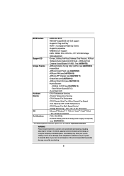
...VCCSA Voltage Multi-adjustment Support CD - ASRock Instant Flash (see CAUTION 13) - ASRock XFast USB (see CAUTION 9) - Boot Failure Guard (B.F.G.) - CPU/Chassis Fan Tachometer - SMBIOS 2.3.1 Support - OEM and Trial; ASRock AIWI (see CAUTION 12) - CPU/... Wake Up Events - Supports jumperfree - Drivers, Utilities, AntiVirus Software (Trial Version), ASRock Software Suite (CyberLink DVD Suite - Creative Sound Blaster X-Fi MB - Trial (H67M-ITX)) Unique Feature - CPU Temperature Sensing Monitor - Chassis Temperature Sensing - CPU/Chassis Fan...
...VCCSA Voltage Multi-adjustment Support CD - ASRock Instant Flash (see CAUTION 13) - ASRock XFast USB (see CAUTION 9) - Boot Failure Guard (B.F.G.) - CPU/Chassis Fan Tachometer - SMBIOS 2.3.1 Support - OEM and Trial; ASRock AIWI (see CAUTION 12) - CPU/... Wake Up Events - Supports jumperfree - Drivers, Utilities, AntiVirus Software (Trial Version), ASRock Software Suite (CyberLink DVD Suite - Creative Sound Blaster X-Fi MB - Trial (H67M-ITX)) Unique Feature - CPU Temperature Sensing Monitor - Chassis Temperature Sensing - CPU/Chassis Fan...
User Manual
Page 10
... mode (S4) or power off (S5). All you can update your iPhone charged much quickly from App store to access ASRock Instant Flash. ASRock APP Charger allows you to quickly charge many Apple devices simultaneously and even supports continuous charging when your iPhone/iPod touch. Just... motion controlled games. If you to control your browser version is no longer only available at Wii. ASRock motherboards are exclusively equipped with the SmartView utility that the USB flash drive or hard drive must use SmartView feature, please make sure your OS version is ...
... mode (S4) or power off (S5). All you can update your iPhone charged much quickly from App store to access ASRock Instant Flash. ASRock APP Charger allows you to quickly charge many Apple devices simultaneously and even supports continuous charging when your iPhone/iPod touch. Just... motion controlled games. If you to control your browser version is no longer only available at Wii. ASRock motherboards are exclusively equipped with the SmartView utility that the USB flash drive or hard drive must use SmartView feature, please make sure your OS version is ...

User Manual
Page 11
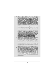
... higher than 50% under 1.00W in off mode condition. For EuP ready power supply selection, we recommend you install the PC system. 15. ASRock XFast USB can boost USB storage device performance. To improve heat dissipation, remember to Intel's suggestion, the EuP ready power supply must meet EuP standard, an EuP ready motherboard...
... higher than 50% under 1.00W in off mode condition. For EuP ready power supply selection, we recommend you install the PC system. 15. ASRock XFast USB can boost USB storage device performance. To improve heat dissipation, remember to Intel's suggestion, the EuP ready power supply must meet EuP standard, an EuP ready motherboard...
User Manual
Page 12
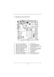
1.3 Motherboard Layout (H67M-ITX/HT) 12 3 4 56 7 8 9 10 11 12 17.0cm (6.7 in) PLED PWRBTN 1 HDLED RESET SATA_0 (port 0) SATA_3 (port 5) 1 1 1 USB6_7 USB8_9 AT X P W R 1 1 SPEAKER1 13 PS2 Keyboard USB 2.0 T: USB0 B: USB1 PANEL1 PLED1 1 CHA_FAN1 SATA_1 (port 1) SATA_2 (port 4) CIR1 MINI_PCIE1 24 23 CPU_FAN1 ...pin module) 17.0cm (6.7 in) 22 HDMI1 ESATA1 21 USB 2.0 T: USB2 B: USB3 CMOS Battery Top: CTR BASS Center: REAR SPK Bottom: Optical SPDIF USB 3.0 T: USB4 Top: B: USB5 RJ-45 HD_AUDIO1 1 ATX12V1 AUDIO CODEC H67M-ITX/HT PCIE1 16 17 Top: LINE IN Center: FRONT ...
1.3 Motherboard Layout (H67M-ITX/HT) 12 3 4 56 7 8 9 10 11 12 17.0cm (6.7 in) PLED PWRBTN 1 HDLED RESET SATA_0 (port 0) SATA_3 (port 5) 1 1 1 USB6_7 USB8_9 AT X P W R 1 1 SPEAKER1 13 PS2 Keyboard USB 2.0 T: USB0 B: USB1 PANEL1 PLED1 1 CHA_FAN1 SATA_1 (port 1) SATA_2 (port 4) CIR1 MINI_PCIE1 24 23 CPU_FAN1 ...pin module) 17.0cm (6.7 in) 22 HDMI1 ESATA1 21 USB 2.0 T: USB2 B: USB3 CMOS Battery Top: CTR BASS Center: REAR SPK Bottom: Optical SPDIF USB 3.0 T: USB4 Top: B: USB5 RJ-45 HD_AUDIO1 1 ATX12V1 AUDIO CODEC H67M-ITX/HT PCIE1 16 17 Top: LINE IN Center: FRONT ...
User Manual
Page 13
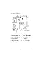
1.4 Motherboard Layout (H67M-ITX) 12 3 4 56 7 8 9 10 11 12 17.0cm (6.7 in) PLED PWRBTN 1 HDLED RESET SATA_0 (port 0) SATA_3 (port 5) 1 1 1 USB6_7 USB8_9 AT X P W R 1 1 SPEAKER1 PS2 Keyboard 22 21 USB 2.0 T: USB0 B: USB1 PANEL1 PLED1 1 CHA_FAN1 SATA_1 (port 1) CPU_FAN1 64Mb BIOS SATA_2 (port 4) Intel CIR1 ...pin module) 17.0cm (6.7 in) 20 HDMI1 ESATA1 19 USB 2.0 T: USB2 B: USB3 CMOS Battery Top: CTR BASS Center: REAR SPK Bottom: Optical SPDIF USB 3.0 T: USB4 Top: B: USB5 RJ-45 HD_AUDIO1 1 ATX12V1 AUDIO CODEC H67M-ITX PCIE1 14 15 Top: LINE IN Center: FRONT Bottom:...
1.4 Motherboard Layout (H67M-ITX) 12 3 4 56 7 8 9 10 11 12 17.0cm (6.7 in) PLED PWRBTN 1 HDLED RESET SATA_0 (port 0) SATA_3 (port 5) 1 1 1 USB6_7 USB8_9 AT X P W R 1 1 SPEAKER1 PS2 Keyboard 22 21 USB 2.0 T: USB0 B: USB1 PANEL1 PLED1 1 CHA_FAN1 SATA_1 (port 1) CPU_FAN1 64Mb BIOS SATA_2 (port 4) Intel CIR1 ...pin module) 17.0cm (6.7 in) 20 HDMI1 ESATA1 19 USB 2.0 T: USB2 B: USB3 CMOS Battery Top: CTR BASS Center: REAR SPK Bottom: Optical SPDIF USB 3.0 T: USB4 Top: B: USB5 RJ-45 HD_AUDIO1 1 ATX12V1 AUDIO CODEC H67M-ITX PCIE1 14 15 Top: LINE IN Center: FRONT Bottom:...

User Manual
Page 14
1.5 I/O Panel (H67M-ITX/HT) 1 2 34 58 69 7 10 16 15 14 13 12 11 1 USB 2.0 Ports (USB01) 2 VGA/D-Sub Port 3 USB 2.0 Ports (USB23) * 4 LAN RJ-45 Port 5 Central / Bass (Orange) 6 Rear Speaker (Black) 7 Optical SPDIF Out Port 8 Line In (Light Blue) ** 9 Front Speaker (Lime) 10 Microphone (Pink) 11 USB 3.0 Ports (USB45) 12 eSATA2 (port 3) Port 13...
1.5 I/O Panel (H67M-ITX/HT) 1 2 34 58 69 7 10 16 15 14 13 12 11 1 USB 2.0 Ports (USB01) 2 VGA/D-Sub Port 3 USB 2.0 Ports (USB23) * 4 LAN RJ-45 Port 5 Central / Bass (Orange) 6 Rear Speaker (Black) 7 Optical SPDIF Out Port 8 Line In (Light Blue) ** 9 Front Speaker (Lime) 10 Microphone (Pink) 11 USB 3.0 Ports (USB45) 12 eSATA2 (port 3) Port 13...

User Manual
Page 15
1.6 I/O Panel (H67M-ITX) 1 2 34 58 69 7 10 15 14 1 USB 2.0 Ports (USB01) 2 VGA/D-Sub Port 3 USB 2.0 Ports (USB23) * 4 LAN RJ-45 Port 5 Central / Bass (Orange) 6 Rear Speaker (Black) 7 Optical SPDIF Out Port 8 Line In (Light Blue) 13 12 11 ** 9 Front Speaker (Lime) 10 Microphone (Pink) 11 USB 3.0 Ports (USB45) 12 eSATA2 (port 3) Port 13 VGA/HDMI...
1.6 I/O Panel (H67M-ITX) 1 2 34 58 69 7 10 15 14 1 USB 2.0 Ports (USB01) 2 VGA/D-Sub Port 3 USB 2.0 Ports (USB23) * 4 LAN RJ-45 Port 5 Central / Bass (Orange) 6 Rear Speaker (Black) 7 Optical SPDIF Out Port 8 Line In (Light Blue) 13 12 11 ** 9 Front Speaker (Lime) 10 Microphone (Pink) 11 USB 3.0 Ports (USB45) 12 eSATA2 (port 3) Port 13 VGA/HDMI...

User Manual
Page 28
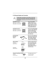
...23 45 GND IRTX IRRX ATX+5VSB 3. When the CIR function is enabled, the other front USB port. * Only one of the chassis on this motherboard. Connect the front USB cable to the front USB port. Please install it on the rear panel. Please make sure the wire assignments and the ...pin assignments are matched correctly. Install the Remote Receiver to the USB 2.0 header (as below procedure for front USB only. The Remote Receiver is able to the USB 2.0 header (USB8_9, see page 12/13, No. 9), which is compatible with a 4-pin CIR header (CIR1...
...23 45 GND IRTX IRRX ATX+5VSB 3. When the CIR function is enabled, the other front USB port. * Only one of the chassis on this motherboard. Connect the front USB cable to the front USB port. Please install it on the rear panel. Please make sure the wire assignments and the ...pin assignments are matched correctly. Install the Remote Receiver to the USB 2.0 header (as below procedure for front USB only. The Remote Receiver is able to the USB 2.0 header (USB8_9, see page 12/13, No. 9), which is compatible with a 4-pin CIR header (CIR1...
User Manual
Page 30
... P-9 P+9 GND DUMMY 1 GND P+8 P-8 USB_PWR Consumer Infrared Module Header (4-pin CIR1) (see p.12/13 No. 9) 1 GND IRTX IRRX ATX+5VSB Besides four default USB 2.0 ports on the I/O panel, there are NOT jumpers. Serial ATA3 Connectors (SATA_0 (port 0): see p.12/13, No. 3) (SATA_1 (port 1): see p.12/13... current SATAII interface allows up to 3.0 Gb/s data transfer rate. 2.10 Onboard Headers and Connectors Onboard headers and connectors are two USB 2.0 headers on this motherboard. The current SATA3 interface allows up to 6.0 Gb/s data transfer rate. Either end of the motherboard!...
... P-9 P+9 GND DUMMY 1 GND P+8 P-8 USB_PWR Consumer Infrared Module Header (4-pin CIR1) (see p.12/13 No. 9) 1 GND IRTX IRRX ATX+5VSB Besides four default USB 2.0 ports on the I/O panel, there are NOT jumpers. Serial ATA3 Connectors (SATA_0 (port 0): see p.12/13, No. 3) (SATA_1 (port 1): see p.12/13... current SATAII interface allows up to 3.0 Gb/s data transfer rate. 2.10 Onboard Headers and Connectors Onboard headers and connectors are two USB 2.0 headers on this motherboard. The current SATA3 interface allows up to 6.0 Gb/s data transfer rate. Either end of the motherboard!...

User Manual
Page 46
... system UEFI without preparing an additional floppy diskette or other complicated flash utility. ASRock Instant Flash ASRock Instant Flash is a UEFI flash utility embedded in Flash ROM. Please be noted that the USB flash drive or hard drive must use FAT32/16/12 file system. Select ...the proper UEFI file to update your UEFI, and reboot your UEFI only in this section, you execute ASRock Instant Flash utility, the utility will show...
... system UEFI without preparing an additional floppy diskette or other complicated flash utility. ASRock Instant Flash ASRock Instant Flash is a UEFI flash utility embedded in Flash ROM. Please be noted that the USB flash drive or hard drive must use FAT32/16/12 file system. Select ...the proper UEFI file to update your UEFI, and reboot your UEFI only in this section, you execute ASRock Instant Flash utility, the utility will show...

User Manual
Page 55
...setup when [Disabled] is recommended to select [Disabled] to enter OS. [UEFI Setup Only] - USB 3.0 Controller Use this option to enable or disable legacy support for USB 3.0 devices. Enables support for the details of these four options: [Enabled] - The default value is... [Enabled]. If you have USB compatibility issue, it is selected. Legacy USB 3.0 Support Use this item to enable or disable the use of USB 3.0 controller. There are connected. [Disabled] - Enables legacy support if USB devices are four configuration options: [Enabled], [...
...setup when [Disabled] is recommended to select [Disabled] to enter OS. [UEFI Setup Only] - USB 3.0 Controller Use this option to enable or disable legacy support for USB 3.0 devices. Enables support for the details of these four options: [Enabled] - The default value is... [Enabled]. If you have USB compatibility issue, it is selected. Legacy USB 3.0 Support Use this item to enable or disable the use of USB 3.0 controller. There are connected. [Disabled] - Enables legacy support if USB devices are four configuration options: [Enabled], [...
Quick Installation Guide
Page 2
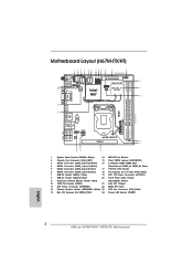
... (SATA_2 (port 4), Blue) 17 1155-Pin CPU Socket 6 SATA2 Connector (SATA_3 (port 5), Blue) 18 PCI Express 2.0 x16 Slot (PCIE1, Blue) 7 USB 2.0 Header (USB6_7, Blue) 19 ATX 12V Power Connector (ATX12V1) 8 USB 2.0 Header (USB8_9, Blue) 20 Front Panel Audio Header 9 Consumer Infrared Module Header (CIR1) (HD_AUDIO1, White) 10 COM Port Header (COM1) 21... SPI Flash 12 Chassis Speaker Header (SPEAKER 1, White) 23 CPU Fan Connector (CPU_FAN1) 13 Mini PCI Express Slot (MINI_PCIE1) 24 Power LED Header (PLED1) English 2 ASRock H67M-ITX/HT / H67M-ITX Motherboard
... (SATA_2 (port 4), Blue) 17 1155-Pin CPU Socket 6 SATA2 Connector (SATA_3 (port 5), Blue) 18 PCI Express 2.0 x16 Slot (PCIE1, Blue) 7 USB 2.0 Header (USB6_7, Blue) 19 ATX 12V Power Connector (ATX12V1) 8 USB 2.0 Header (USB8_9, Blue) 20 Front Panel Audio Header 9 Consumer Infrared Module Header (CIR1) (HD_AUDIO1, White) 10 COM Port Header (COM1) 21... SPI Flash 12 Chassis Speaker Header (SPEAKER 1, White) 23 CPU Fan Connector (CPU_FAN1) 13 Mini PCI Express Slot (MINI_PCIE1) 24 Power LED Header (PLED1) English 2 ASRock H67M-ITX/HT / H67M-ITX Motherboard

Quick Installation Guide
Page 3
...) 17.0cm (6.7 in) 20 HDMI1 ESATA1 19 USB 2.0 T: USB2 B: USB3 CMOS Battery Top: CTR BASS Center: REAR SPK Bottom: Optical SPDIF USB 3.0 T: USB4 Top: B: USB5 RJ-45 HD_AUDIO1 1 ATX12V1 AUDIO CODEC H67M-ITX PCIE1 14 15 Top: LINE IN Center: FRONT ...USB 2.0 Header (USB8_9, Blue) (HD_AUDIO1, White) 9 Consumer Infrared Module Header (CIR1) 19 Intel H67 Chipset 10 COM Port Header (COM1) 20 64Mb SPI Flash 11 ATX Power Connector (ATXPWR1) 21 CPU Fan Connector (CPU_FAN1) 12 Chassis Speaker Header (SPEAKER 1, White) 22 Power LED Header (PLED1) English 3 ASRock H67M-ITX/HT / H67M-ITX...
...) 17.0cm (6.7 in) 20 HDMI1 ESATA1 19 USB 2.0 T: USB2 B: USB3 CMOS Battery Top: CTR BASS Center: REAR SPK Bottom: Optical SPDIF USB 3.0 T: USB4 Top: B: USB5 RJ-45 HD_AUDIO1 1 ATX12V1 AUDIO CODEC H67M-ITX PCIE1 14 15 Top: LINE IN Center: FRONT ...USB 2.0 Header (USB8_9, Blue) (HD_AUDIO1, White) 9 Consumer Infrared Module Header (CIR1) 19 Intel H67 Chipset 10 COM Port Header (COM1) 20 64Mb SPI Flash 11 ATX Power Connector (ATXPWR1) 21 CPU Fan Connector (CPU_FAN1) 12 Chassis Speaker Header (SPEAKER 1, White) 22 Power LED Header (PLED1) English 3 ASRock H67M-ITX/HT / H67M-ITX...

Quick Installation Guide
Page 4
...) * 4 LAN RJ-45 Port 5 Central / Bass (Orange) 6 Rear Speaker (Black) 7 Optical SPDIF Out Port 8 Line In (Light Blue) ** 9 Front Speaker (Lime) 10 Microphone (Pink) 11 USB 3.0 Ports (USB45) 12 eSATA2 (port 3) Port 13 VGA/HDMI Port 14 VGA/DVI-D Port 15 PS/2 Keyboard Port (Purple) 16 Antenna Ports * There are allowed... "Realtek HDA Primary output" to use Rear Speaker, Central/Bass, and Front Speaker, or select "Realtek HDA Audio 2nd output" to use front panel audio. 4 ASRock H67M-ITX/HT / H67M-ITX Motherboard English
...) * 4 LAN RJ-45 Port 5 Central / Bass (Orange) 6 Rear Speaker (Black) 7 Optical SPDIF Out Port 8 Line In (Light Blue) ** 9 Front Speaker (Lime) 10 Microphone (Pink) 11 USB 3.0 Ports (USB45) 12 eSATA2 (port 3) Port 13 VGA/HDMI Port 14 VGA/DVI-D Port 15 PS/2 Keyboard Port (Purple) 16 Antenna Ports * There are allowed... "Realtek HDA Primary output" to use Rear Speaker, Central/Bass, and Front Speaker, or select "Realtek HDA Audio 2nd output" to use front panel audio. 4 ASRock H67M-ITX/HT / H67M-ITX Motherboard English

Quick Installation Guide
Page 5
...port LED indications. Please select "Mixer ToolBox" , click "Enable playback multi-streaming", and click "ok". I/O Panel (H67M-ITX) 1 2 34 58 69 7 10 15 14 1 USB 2.0 Ports (USB01) 2 VGA/D-Sub Port 3 USB 2.0 Ports (USB23) * 4 LAN RJ-45 Port 5 Central / Bass (Orange) 6 Rear Speaker (Black) 7 ... 1Gbps connection LAN Port ** If you will find "Mixer" tool on your computer, you use front panel audio. 5 ASRock H67M-ITX/HT / H67M-ITX Motherboard English TABLE for Audio Output Connection Audio Output Channels Front Speaker Rear Speaker Central / Bass Line In or (No. 9) (No...
...port LED indications. Please select "Mixer ToolBox" , click "Enable playback multi-streaming", and click "ok". I/O Panel (H67M-ITX) 1 2 34 58 69 7 10 15 14 1 USB 2.0 Ports (USB01) 2 VGA/D-Sub Port 3 USB 2.0 Ports (USB23) * 4 LAN RJ-45 Port 5 Central / Bass (Orange) 6 Rear Speaker (Black) 7 ... 1Gbps connection LAN Port ** If you will find "Mixer" tool on your computer, you use front panel audio. 5 ASRock H67M-ITX/HT / H67M-ITX Motherboard English TABLE for Audio Output Connection Audio Output Channels Front Speaker Rear Speaker Central / Bass Line In or (No. 9) (No...

Quick Installation Guide
Page 11
Front panel audio connector - 2 x USB 2.0 headers (support 4 USB 2.0 ports) English 11 ASRock H67M-ITX/HT / H67M-ITX Motherboard Realtek RTL8111E - Supports Wake-On-LAN - HD Audio Jack: Rear Speaker/Central/Bass/Line in/Front Speaker/Microphone (see CAUTION 7) - 2 x SATA3 6.0 Gb/s connectors, support ...
Front panel audio connector - 2 x USB 2.0 headers (support 4 USB 2.0 ports) English 11 ASRock H67M-ITX/HT / H67M-ITX Motherboard Realtek RTL8111E - Supports Wake-On-LAN - HD Audio Jack: Rear Speaker/Central/Bass/Line in/Front Speaker/Microphone (see CAUTION 7) - 2 x SATA3 6.0 Gb/s connectors, support ...

Quick Installation Guide
Page 12
Supports "Plug and Play" - Trial (H67M-ITX)) Unique Feature - ASRock XFast USB (see CAUTION 10) - Good Night LED Hardware - CPU Temperature Sensing Monitor - CPU/Chassis Quiet Fan (Allow Chassis Fan Speed Auto-Adjust by... Tuning Utility (AXTU) (see CAUTION 14) - BIOS Feature - 64Mb AMI BIOS - OEM and Trial; ASRock APP Charger (see CAUTION 12) - SmartView (see CAUTION 11) - English 12 ASRock H67M-ITX/HT / H67M-ITX Motherboard AMI UEFI Legal BIOS with overclocking, including adjusting the setting in the BIOS, applying Untied Overclocking Technology, or...
Supports "Plug and Play" - Trial (H67M-ITX)) Unique Feature - ASRock XFast USB (see CAUTION 10) - Good Night LED Hardware - CPU Temperature Sensing Monitor - CPU/Chassis Quiet Fan (Allow Chassis Fan Speed Auto-Adjust by... Tuning Utility (AXTU) (see CAUTION 14) - BIOS Feature - 64Mb AMI BIOS - OEM and Trial; ASRock APP Charger (see CAUTION 12) - SmartView (see CAUTION 11) - English 12 ASRock H67M-ITX/HT / H67M-ITX Motherboard AMI UEFI Legal BIOS with overclocking, including adjusting the setting in the BIOS, applying Untied Overclocking Technology, or...


