
User Manual
Page 1
H61MV-ITX User Manual Version 1.0 Published November 2012 Copyright©2012 ASRock INC. All rights reserved. 1
H61MV-ITX User Manual Version 1.0 Published November 2012 Copyright©2012 ASRock INC. All rights reserved. 1

User Manual
Page 2
...to the owners' benefit, without intent to change without written consent of merchantability or fitness for a particular purpose. ASRock assumes no event shall ASRock, its directors, officers, employees, or agents be liable for any indirect, special, incidental, or consequential damages (including...this device must accept any interference received, including interference that may apply, see www.dtsc.ca.gov/hazardouswaste/perchlorate" ASRock Website: http://www.asrock.com 2 Copyright Notice: No part of this manual may be reproduced, transcribed, transmitted, or translated in any language...
...to the owners' benefit, without intent to change without written consent of merchantability or fitness for a particular purpose. ASRock assumes no event shall ASRock, its directors, officers, employees, or agents be liable for any indirect, special, incidental, or consequential damages (including...this device must accept any interference received, including interference that may apply, see www.dtsc.ca.gov/hazardouswaste/perchlorate" ASRock Website: http://www.asrock.com 2 Copyright Notice: No part of this manual may be reproduced, transcribed, transmitted, or translated in any language...

User Manual
Page 3
...Heatsink and CPU fan 19 2.5 Installation of Memory Modules (DIMM 20 2.6 Expansion Slot (PCI Express Slot 21 2.7 Dual Monitor and Surround Display Features 22 2.8 ASRock Smart Remote Installation Guide 25 2.9 Jumpers Setup 27 2.10 Onboard Headers and Connectors 28 2.11 Serial ATA (SATA) / Serial ATA2 (SATA2) Hard Disks ...XP 64-bit Without RAID Functions 35 2.15.2 Installing Windows® 8 / 8 64-bit / 7 / 7 64-bit / VistaTM / VistaTM 64-bit Without RAID Functions. 36 2.16 ASRock XFast 555 37 2.16.1 ASRock XFast RAM 38 2.16.2 ASRock XFast LAN 41 2.16.3 ASRock XFast USB 45 3
...Heatsink and CPU fan 19 2.5 Installation of Memory Modules (DIMM 20 2.6 Expansion Slot (PCI Express Slot 21 2.7 Dual Monitor and Surround Display Features 22 2.8 ASRock Smart Remote Installation Guide 25 2.9 Jumpers Setup 27 2.10 Onboard Headers and Connectors 28 2.11 Serial ATA (SATA) / Serial ATA2 (SATA2) Hard Disks ...XP 64-bit Without RAID Functions 35 2.15.2 Installing Windows® 8 / 8 64-bit / 7 / 7 64-bit / VistaTM / VistaTM 64-bit Without RAID Functions. 36 2.16 ASRock XFast 555 37 2.16.1 ASRock XFast RAM 38 2.16.2 ASRock XFast LAN 41 2.16.3 ASRock XFast USB 45 3

User Manual
Page 4
3 UEFI SETUP UTILITY 47 3.1 Introduction 47 3.1.1 UEFI Menu Bar 47 3.1.2 Navigation Keys 48 3.2 Main Screen 48 3.3 OC Tweaker Screen 49 3.4 Advanced Screen 53 3.4.1 CPU Configuration 54 3.4.2 North Bridge Configuration 56 3.4.3 South Bridge Configuration 57 3.4.4 Storage Configuration 58 3.4.5 Intel(R) Rapid Start Technology 59 3.4.6 Intel(R) Smart Connect Technology 60 3.4.7 ACPI Configuration 61 3.4.8 USB Configuration 62 3.5 Tool 63 3.6 Hardware Health Event Monitoring Screen 65 3.7 Boot Screen 66 3.8 Security Screen 68 3.9 Exit Screen 69 4 Software Support 70 4.1 ...
3 UEFI SETUP UTILITY 47 3.1 Introduction 47 3.1.1 UEFI Menu Bar 47 3.1.2 Navigation Keys 48 3.2 Main Screen 48 3.3 OC Tweaker Screen 49 3.4 Advanced Screen 53 3.4.1 CPU Configuration 54 3.4.2 North Bridge Configuration 56 3.4.3 South Bridge Configuration 57 3.4.4 Storage Configuration 58 3.4.5 Intel(R) Rapid Start Technology 59 3.4.6 Intel(R) Smart Connect Technology 60 3.4.7 ACPI Configuration 61 3.4.8 USB Configuration 62 3.5 Tool 63 3.6 Hardware Health Event Monitoring Screen 65 3.7 Boot Screen 66 3.8 Security Screen 68 3.9 Exit Screen 69 4 Software Support 70 4.1 ...
User Manual
Page 5
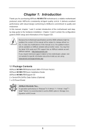
... installation. It delivers excellent performance with robust design conforming to ASRock's commitment to change without further notice. www.asrock.com/support/index.asp 1.1 Package Contents ASRock H61MV-ITX Motherboard (Mini-ITX Form Factor) ASRock H61MV-ITX Quick Installation Guide ASRock H61MV-ITX Support CD 2 x Serial ATA (SATA) Data Cables (Optional) 1 x I/O Panel Shield ASRock Reminds You... Because the motherboard specifications and the BIOS software...
... installation. It delivers excellent performance with robust design conforming to ASRock's commitment to change without further notice. www.asrock.com/support/index.asp 1.1 Package Contents ASRock H61MV-ITX Motherboard (Mini-ITX Form Factor) ASRock H61MV-ITX Quick Installation Guide ASRock H61MV-ITX Support CD 2 x Serial ATA (SATA) Data Cables (Optional) 1 x I/O Panel Shield ASRock Reminds You... Because the motherboard specifications and the BIOS software...

User Manual
Page 6
... slot (PCIE1 @ x16 mode) * PCIE 3.0 is only supported with Intel® Sandy Bridge CPU. - Supports Intel® HD Graphics Built-in LGA1155 Package - Max. Mini-ITX Form Factor -
... slot (PCIE1 @ x16 mode) * PCIE 3.0 is only supported with Intel® Sandy Bridge CPU. - Supports Intel® HD Graphics Built-in LGA1155 Package - Max. Mini-ITX Form Factor -

User Manual
Page 7
resolution up to 1920x1200 @ 60Hz - HD Audio Jack: Line in / Front Speaker / Microphone - 4 x SATA2 3.0 Gb/s connectors, support NCQ, AHCI and Hot Plug functions - 1 x CIR header - 1 x HDMI_SPDIF header - 1 x Chassis Intrusion header - 1 x CPU Fan connectors (4-pin) - 1 x Chassis Fan connector (3-pin) - 24 pin ATX power connector - 4 pin 12V power connector - Supports "Plug and Play" - resolution up to -Use USB 2.0 Ports - 1 x RJ-45 LAN Port with LED (ACT/LINK LED and SPEED LED) - Supports Auto Lip Sync, xvYCC and HBR (High Bit Rate Audio) with HDMI port - Supports HDCP function ...
resolution up to 1920x1200 @ 60Hz - HD Audio Jack: Line in / Front Speaker / Microphone - 4 x SATA2 3.0 Gb/s connectors, support NCQ, AHCI and Hot Plug functions - 1 x CIR header - 1 x HDMI_SPDIF header - 1 x Chassis Intrusion header - 1 x CPU Fan connectors (4-pin) - 1 x Chassis Fan connector (3-pin) - 24 pin ATX power connector - 4 pin 12V power connector - Supports "Plug and Play" - resolution up to -Use USB 2.0 Ports - 1 x RJ-45 LAN Port with LED (ACT/LINK LED and SPEED LED) - Supports Auto Lip Sync, xvYCC and HBR (High Bit Rate Audio) with HDMI port - Supports HDCP function ...

User Manual
Page 8
... by overclocking. 8 FCC, CE, WHQL - ErP/EuP Ready (ErP/EuP ready power supply is required) * For detailed product information, please visit our website: http://www.asrock.com WARNING Please realize that there is a certain risk involved with overclocking, including adjusting the setting in the BIOS, applying Untied Overclocking Technology, or using...
... by overclocking. 8 FCC, CE, WHQL - ErP/EuP Ready (ErP/EuP ready power supply is required) * For detailed product information, please visit our website: http://www.asrock.com WARNING Please realize that there is a certain risk involved with overclocking, including adjusting the setting in the BIOS, applying Untied Overclocking Technology, or using...

User Manual
Page 9
HBR is supported under Windows® 8 64-bit / 8 / 7 64-bit / 7. CAUTION! 1. xvYCC is no such limitation. Due to utilize the memory that Windows® cannot use. 2. For Windows® OS with 64bit CPU, there is only supported under Windows® 8 64-bit / 8 / 7 64-bit / 7 / VistaTM 64-bit / VistaTM. 9 You can use ASRock XFast RAM to the operating system limitation, the actual memory size may be less than 4GB for the reservation for system usage under Windows® 8 / 7 / VistaTM / XP.
HBR is supported under Windows® 8 64-bit / 8 / 7 64-bit / 7. CAUTION! 1. xvYCC is no such limitation. Due to utilize the memory that Windows® cannot use. 2. For Windows® OS with 64bit CPU, there is only supported under Windows® 8 64-bit / 8 / 7 64-bit / 7 / VistaTM 64-bit / VistaTM. 9 You can use ASRock XFast RAM to the operating system limitation, the actual memory size may be less than 4GB for the reservation for system usage under Windows® 8 / 7 / VistaTM / XP.

User Manual
Page 10
... preparing an additional floppy diskette or other complicated flash utility. In Hardware Monitor, it shows the major readings of your system. ASRock Instant Boot ASRock Instant Boot allows you to turn on your PC in just a few seconds, provides a much more efficient way to save ... features which includes Hardware Monitor, Fan Control and XFast RAM. Just launch this utility, you to adjust. 1.3 Unique Features ASRock Extreme Tuning Utility (AXTU) ASRock Extreme Tuning Utility (AXTU) is a BIOS flash utility embedded in Flash ROM. This convenient BIOS update tool allows you can...
... preparing an additional floppy diskette or other complicated flash utility. In Hardware Monitor, it shows the major readings of your system. ASRock Instant Boot ASRock Instant Boot allows you to turn on your PC in just a few seconds, provides a much more efficient way to save ... features which includes Hardware Monitor, Fan Control and XFast RAM. Just launch this utility, you to adjust. 1.3 Unique Features ASRock Extreme Tuning Utility (AXTU) ASRock Extreme Tuning Utility (AXTU) is a BIOS flash utility embedded in Flash ROM. This convenient BIOS update tool allows you can...

User Manual
Page 11
...install the APP Charger driver, it makes your iPhone charge much quickly from your Apple devices, such as iPhone/iPad/iPod Touch, ASRock has prepared a wonderful solution for you are transferring currently. The performance may depend on the properties of charging your computer and up... to extend their lifespan. 11 ASRock XFast USB ASRock XFast USB can watch Youtube HD videos and download simultaneously. And it also boosts the speed of accessing your application's ...
...install the APP Charger driver, it makes your iPhone charge much quickly from your Apple devices, such as iPhone/iPad/iPod Touch, ASRock has prepared a wonderful solution for you are transferring currently. The performance may depend on the properties of charging your computer and up... to extend their lifespan. 11 ASRock XFast USB ASRock XFast USB can watch Youtube HD videos and download simultaneously. And it also boosts the speed of accessing your application's ...

User Manual
Page 12
...other words, the system can autodetect the latest UEFI from our servers and flash them without permission to enable this feature. ASRock Dehumidifier Function Users may schedule the starting and ending hours of internet access granted to establish an internet curfew or restrict ...other users. When enabling Dehumidifier Function, the computer will power on a DHCP configured computer in the root directory of failing. ASRock Internet Flash ASRock Internet Flash searches for available UEFI firmware updates from our servers. Please note that BIOS files need to be running on ...
...other words, the system can autodetect the latest UEFI from our servers and flash them without permission to enable this feature. ASRock Dehumidifier Function Users may schedule the starting and ending hours of internet access granted to establish an internet curfew or restrict ...other users. When enabling Dehumidifier Function, the computer will power on a DHCP configured computer in the root directory of failing. ASRock Internet Flash ASRock Internet Flash searches for available UEFI firmware updates from our servers. Please note that BIOS files need to be running on ...

User Manual
Page 13
ASRock Restart to UEFI Windows® 8 brings the ultimate boot up speed makes it hard to access the UEFI setup. It allows users to easily enter ... access. the PC will be assured to UEFI technology is on the PC next time. Not only this function; ASRock Restart to access the UEFI directly in the very beginning. ASRock Good Night LED ASRock Good Night LED technology can offer you a better environment by extinguishing the unessential LED. The lightning boot up...
ASRock Restart to UEFI Windows® 8 brings the ultimate boot up speed makes it hard to access the UEFI setup. It allows users to easily enter ... access. the PC will be assured to UEFI technology is on the PC next time. Not only this function; ASRock Restart to access the UEFI directly in the very beginning. ASRock Good Night LED ASRock Good Night LED technology can offer you a better environment by extinguishing the unessential LED. The lightning boot up...

User Manual
Page 14
... 1 USB6_7 1 AT X P W R 1 CI1 21 CHA_FAN1 SATA_1 (PORT 1) SATA_3 (PORT 5) 1 1 CIR1 PLED PWRBTN DDR3 VGA1 1 CLRCMOS1 1 HDLED RESET PANEL1 Intel 32Mb 13 BIOS H61 20 CPU_FAN1 H61MV-ITX HDMI1 RoHS ATX12V1 CMOS Battery DDR3_A1 (64 bit, 240-pin module) DDR3_B1 (64 bit, 240-pin module) USB 2.0 T: USB0 B: USB1 19 USB 2.0 T: USB2 B: USB3 Top...
... 1 USB6_7 1 AT X P W R 1 CI1 21 CHA_FAN1 SATA_1 (PORT 1) SATA_3 (PORT 5) 1 1 CIR1 PLED PWRBTN DDR3 VGA1 1 CLRCMOS1 1 HDLED RESET PANEL1 Intel 32Mb 13 BIOS H61 20 CPU_FAN1 H61MV-ITX HDMI1 RoHS ATX12V1 CMOS Battery DDR3_A1 (64 bit, 240-pin module) DDR3_B1 (64 bit, 240-pin module) USB 2.0 T: USB0 B: USB1 19 USB 2.0 T: USB2 B: USB3 Top...

User Manual
Page 15
Please refer to the table below steps for the LAN port LED indications. LAN Port LED Indications Activity/Link LED SPEED LED Status Description Status Description ACT/LINK SPEED LED LED Off No Link Off 10Mbps connection Blinking Data Activity Orange 100Mbps connection On Link Green 1Gbps connection LAN Port ** To enable Multi-Streaming function, you are two LED next to the LAN port. Then reboot your system. 15 Click "Device advanced settings", choose "Make front and rear output devices playbacks two different audio streams simultaneously", and click "ok"....
Please refer to the table below steps for the LAN port LED indications. LAN Port LED Indications Activity/Link LED SPEED LED Status Description Status Description ACT/LINK SPEED LED LED Off No Link Off 10Mbps connection Blinking Data Activity Orange 100Mbps connection On Link Green 1Gbps connection LAN Port ** To enable Multi-Streaming function, you are two LED next to the LAN port. Then reboot your system. 15 Click "Device advanced settings", choose "Make front and rear output devices playbacks two different audio streams simultaneously", and click "ok"....

User Manual
Page 16
... note of your motherboard directly on a grounded antistatic pad or in the bag that the power is switched off or the power cord is a Mini-ITX form factor motherboard. Doing so may cause severe damage to the chassis. Hold components by circles to secure the motherboard to the motherboard, peripherals, and...
... note of your motherboard directly on a grounded antistatic pad or in the bag that the power is switched off or the power cord is a Mini-ITX form factor motherboard. Doing so may cause severe damage to the chassis. Hold components by circles to secure the motherboard to the motherboard, peripherals, and...

User Manual
Page 17
2.3 CPU Installation For the installation of Intel 1155-Pin CPU, please follow the steps below. 1155-Pin Socket Overview Before you insert the 1155-Pin CPU into the socket if above situation is found. Disengaging the lever by depressing down and out on the socket. Rotate the load lever to handle and avoid kicking off the PnP cap. 2. Remove PnP Cap (Pick and Place Cap). 1. Step 1. Step 2. Do not force to insert the CPU into the socket, please check if the CPU surface is unclean or if there is recommended to use the cap tab to fully open position at approximately 135 ...
2.3 CPU Installation For the installation of Intel 1155-Pin CPU, please follow the steps below. 1155-Pin Socket Overview Before you insert the 1155-Pin CPU into the socket if above situation is found. Disengaging the lever by depressing down and out on the socket. Rotate the load lever to handle and avoid kicking off the PnP cap. 2. Remove PnP Cap (Pick and Place Cap). 1. Step 1. Step 2. Do not force to insert the CPU into the socket, please check if the CPU surface is unclean or if there is recommended to use the cap tab to fully open position at approximately 135 ...

User Manual
Page 18
Locate Pin1 and the two orientation key notches. Step 3-4. Close the socket: Step 4-1. While pressing down lightly on load plate, engage the load lever. 18 Carefully place the CPU into the socket by the edge where is within the socket and properly mated to match the two orientation key notches of the socket. Insert the 1155-Pin CPU: Step 3-1. Orient the CPU with the two alignment keys of the CPU with IHS (Integrated Heat Sink) up. orientation key notch alignment key Pin1 Pin1 orientation key notch 1155-Pin CPU alignment key 1155-Pin Socket For proper inserting...
Locate Pin1 and the two orientation key notches. Step 3-4. Close the socket: Step 4-1. While pressing down lightly on load plate, engage the load lever. 18 Carefully place the CPU into the socket by the edge where is within the socket and properly mated to match the two orientation key notches of the socket. Insert the 1155-Pin CPU: Step 3-1. Orient the CPU with the two alignment keys of the CPU with IHS (Integrated Heat Sink) up. orientation key notch alignment key Pin1 Pin1 orientation key notch 1155-Pin CPU alignment key 1155-Pin Socket For proper inserting...

User Manual
Page 19
For proper installation, please kindly refer to the CPU_FAN connector (CPU_FAN1, see page 14, No. 18). Place the heatsink onto the socket. Step 4. Then connect the CPU fan to the instruction manuals of your CPU fan and heatsink. Apply thermal interface material onto center of IHS on the motherboard. Align fasteners with remaining fasteners. Connect fan header with tie-wrap to install and lock. 2.4 Installation of CPU Fan and Heatsink This motherboard is an example to illustrate the installation of the heatsink for 1155-Pin CPU. Ensure that supports Intel 1155-Pin ...
For proper installation, please kindly refer to the CPU_FAN connector (CPU_FAN1, see page 14, No. 18). Place the heatsink onto the socket. Step 4. Then connect the CPU fan to the instruction manuals of your CPU fan and heatsink. Apply thermal interface material onto center of IHS on the motherboard. Align fasteners with remaining fasteners. Connect fan header with tie-wrap to install and lock. 2.4 Installation of CPU Fan and Heatsink This motherboard is an example to illustrate the installation of the heatsink for 1155-Pin CPU. Ensure that supports Intel 1155-Pin ...

User Manual
Page 20
For dual channel configuration, you always need to install two identical (the same brand, speed, size and chiptype) memory modules in place and the DIMM is not recommended to activate the Dual Channel Memory Technology. 3. It will operate at incorrect orientation. It is unable to install them on this motherboard. Some DDR3 1GB double-sided DIMMs with 16 chips may be damaged. 2. Installing a DIMM Please make sure to install a DDR or DDR2 memory module into the slot at single channel mode. 1. Firmly insert the DIMM into the slot until the retaining clips at both ends ...
For dual channel configuration, you always need to install two identical (the same brand, speed, size and chiptype) memory modules in place and the DIMM is not recommended to activate the Dual Channel Memory Technology. 3. It will operate at incorrect orientation. It is unable to install them on this motherboard. Some DDR3 1GB double-sided DIMMs with 16 chips may be damaged. 2. Installing a DIMM Please make sure to install a DDR or DDR2 memory module into the slot at single channel mode. 1. Firmly insert the DIMM into the slot until the retaining clips at both ends ...