User Manual
Page 6
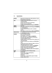
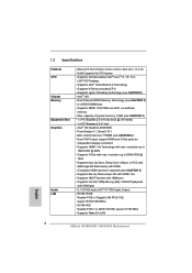
... - resolution up to 2048x1536 @ 75Hz - Supports 2nd Generation Intel® CoreTM i7 / i5 / i3 in , 22.6 cm x 17.3 cm - Supports HDMI 1.4a Technology with HDMI 1.4a - Supports D-Sub with HDMI port - Max. H61M-HVS Realtek PCIE x1 LAN RTL8105E, speed 10/100 Mb/s - ...1.2 Specifications Platform CPU Chipset Memory Expansion Slot Graphics Audio LAN - Supports Intel® Turbo Boost 2.0 Technology - Solid Capacitor for CPU power - Supports K-Series...
... - resolution up to 2048x1536 @ 75Hz - Supports 2nd Generation Intel® CoreTM i7 / i5 / i3 in , 22.6 cm x 17.3 cm - Supports HDMI 1.4a Technology with HDMI 1.4a - Supports D-Sub with HDMI port - Max. H61M-HVS Realtek PCIE x1 LAN RTL8105E, speed 10/100 Mb/s - ...1.2 Specifications Platform CPU Chipset Memory Expansion Slot Graphics Audio LAN - Supports Intel® Turbo Boost 2.0 Technology - Solid Capacitor for CPU power - Supports K-Series...
User Manual
Page 9
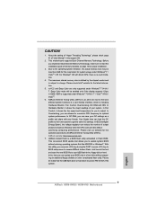
... In OC DNA, you are only supported under Windows® 7 64-bit / 7. Please visit our website for proper installation. 3. ASRock website: http://www.asrock.com 7. Please be enabled only if the display supports 12bpc in a few clicks without preparing an additional floppy diskette or other complicated... BIOS file to your USB flash drive, floppy disk or hard drive, then you to change. Please check Intel® website for optimal system performance. In IES (Intelligent Energy Saver), the voltage regulator can press key during the POST or press...
... In OC DNA, you are only supported under Windows® 7 64-bit / 7. Please visit our website for proper installation. 3. ASRock website: http://www.asrock.com 7. Please be enabled only if the display supports 12bpc in a few clicks without preparing an additional floppy diskette or other complicated... BIOS file to your USB flash drive, floppy disk or hard drive, then you to change. Please check Intel® website for optimal system performance. In IES (Intelligent Energy Saver), the voltage regulator can press key during the POST or press...

User Manual
Page 11
According to Intel's suggestion, the EuP ready power supply must meet EuP standard, an EuP ready motherboard and an EuP ready power supply are required. According to EuP, ...
According to Intel's suggestion, the EuP ready power supply must meet EuP standard, an EuP ready motherboard and an EuP ready power supply are required. According to EuP, ...
User Manual
Page 12
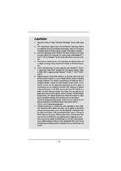
1.3 Motherboard Layout (H61M-HVGS / H61M-HVS) PS2 Mouse PS2 Keyboard 1 17.3cm (6.8 in) 23 HDMI 1.4a ...IN PCI Express 2.0 PWR_FAN1 LAN PHY 5 22 PCIE1 AUDIO CODEC Super I/O CLRCMOS1 1 CMOS 21 Battery 20 PCIE2 Intel 6 H61 32Mb BIOS 7 HD_AUDIO1 1 1 LPT1 USB8_9 1 SATA2_3 SATA2_1 SPEAKER1 1 CHA_FAN1 8 COM1 USB6_7 PLED PWRBTN...CPU_FAN1) 4 ATX Power Connector (ATXPWR1) 5 2 x 240-pin DDR3 DIMM Slots (Dual Channel: DDR3_A1, DDR3_B1, Blue) 6 Intel H61 Chipset 7 32Mb SPI Flash 8 SATA2 Connector (SATA2_1, Blue) 9 Chassis Fan Connector (CHA_FAN1) 10 SATA2 Connector (SATA2_0, ...
1.3 Motherboard Layout (H61M-HVGS / H61M-HVS) PS2 Mouse PS2 Keyboard 1 17.3cm (6.8 in) 23 HDMI 1.4a ...IN PCI Express 2.0 PWR_FAN1 LAN PHY 5 22 PCIE1 AUDIO CODEC Super I/O CLRCMOS1 1 CMOS 21 Battery 20 PCIE2 Intel 6 H61 32Mb BIOS 7 HD_AUDIO1 1 1 LPT1 USB8_9 1 SATA2_3 SATA2_1 SPEAKER1 1 CHA_FAN1 8 COM1 USB6_7 PLED PWRBTN...CPU_FAN1) 4 ATX Power Connector (ATXPWR1) 5 2 x 240-pin DDR3 DIMM Slots (Dual Channel: DDR3_A1, DDR3_B1, Blue) 6 Intel H61 Chipset 7 32Mb SPI Flash 8 SATA2 Connector (SATA2_1, Blue) 9 Chassis Fan Connector (CHA_FAN1) 10 SATA2 Connector (SATA2_0, ...
User Manual
Page 16
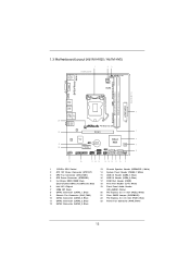
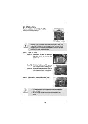
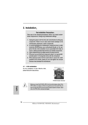
... cap. 2. Remove PnP Cap (Pick and Place Cap). 1. Open the socket: Step 1-1. Do not force to clear retention tab. 2.3 CPU Installation For the installation of Intel 1155-Pin CPU, please follow the steps below. Step 2. Step 1. Step 1-2. It is found.
... cap. 2. Remove PnP Cap (Pick and Place Cap). 1. Open the socket: Step 1-1. Do not force to clear retention tab. 2.3 CPU Installation For the installation of Intel 1155-Pin CPU, please follow the steps below. Step 2. Step 1. Step 1-2. It is found.

User Manual
Page 18
...on the socket surface. Below is equipped with each other components. Align fasteners with the CPU fan connector on fastener caps with Intel 1155Pin CPU to dissipate heat. Apply thermal interface material onto center of your CPU fan and heatsink. Fan cables on side ... for 1155-Pin CPU. Rotate the fastener clockwise, then press down the fasteners without rotating them clockwise, the heatsink cannot be noticed that supports Intel 1155-Pin CPU. Step 1. Step 3. Please be secured on the motherboard (CPU_ FAN1, see page 12, No. 3). Apply Thermal Interface ...
...on the socket surface. Below is equipped with each other components. Align fasteners with the CPU fan connector on fastener caps with Intel 1155Pin CPU to dissipate heat. Apply thermal interface material onto center of your CPU fan and heatsink. Fan cables on side ... for 1155-Pin CPU. Rotate the fastener clockwise, then press down the fasteners without rotating them clockwise, the heatsink cannot be noticed that supports Intel 1155-Pin CPU. Step 1. Step 3. Please be secured on the motherboard (CPU_ FAN1, see page 12, No. 3). Apply Thermal Interface ...

User Manual
Page 23
A. Click the number "2" icon. Repeat steps A through C for the display icon identified by Intel® for protecting digital entertainment content that uses the DVI interface. Click and drag the display icons to positions representing the physical setup of your ...
A. Click the number "2" icon. Repeat steps A through C for the display icon identified by Intel® for protecting digital entertainment content that uses the DVI interface. Click and drag the display icons to positions representing the physical setup of your ...

User Manual
Page 29
STEP 2: Connect the SATA power cable to install the SATA / SATAII hard disks. Intel® H61 chipset provides hardware support for Advanced Host controller Interface (AHCI), a new programming interface for the action to insert and remove the SATA / SATAII .... This section will guide you to the SATA / SATAII hard disk. nector. 2.10 Serial ATA (SATA) / Serial ATAII (SATAII) Hard Disks Installation This motherboard adopts Intel® H61 chipset that it is Hot Plug Function? If the SATA / SATAII HDDs are NOT set for RAID configuration, it cannot perform...
STEP 2: Connect the SATA power cable to install the SATA / SATAII hard disks. Intel® H61 chipset provides hardware support for Advanced Host controller Interface (AHCI), a new programming interface for the action to insert and remove the SATA / SATAII .... This section will guide you to the SATA / SATAII hard disk. nector. 2.10 Serial ATA (SATA) / Serial ATAII (SATAII) Hard Disks Installation This motherboard adopts Intel® H61 chipset that it is Hot Plug Function? If the SATA / SATAII HDDs are NOT set for RAID configuration, it cannot perform...

User Manual
Page 33
.... STEP 2: Install Windows® 7 / 7 64-bit / VistaTM / VistaTM 64-bit OS on your system. 33 When prompted, insert the SATA / SATAII driver diskette containing the Intel® AHCI driver. A. STEP 2: Install Windows® XP / XP 64-bit OS on your system. 2.14.2 Installing Windows® 7 / 7 64-bit / VistaTM / VistaTM 64-bit...
.... STEP 2: Install Windows® 7 / 7 64-bit / VistaTM / VistaTM 64-bit OS on your system. 33 When prompted, insert the SATA / SATAII driver diskette containing the Intel® AHCI driver. A. STEP 2: Install Windows® XP / XP 64-bit OS on your system. 2.14.2 Installing Windows® 7 / 7 64-bit / VistaTM / VistaTM 64-bit...
User Manual
Page 37
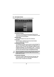
...note that overclocking may reduce CPU voltage and lead to run faster than marked frequency in specific condition. The default value is Intel's new power saving technology. Turbo Boost allows processor cores to system stability or compatibility issue with some power supplies. 3.3 OC Tweaker ...Over Clock by Internal Graphics Device. Please set this item to [Disable] if above issue occurs. Intel Turbo Boost Technology Use this item to enable or disable Intel Turbo Boost Technology. Please note that enabling this function may cause damage to change the ratio value of...
...note that overclocking may reduce CPU voltage and lead to run faster than marked frequency in specific condition. The default value is Intel's new power saving technology. Turbo Boost allows processor cores to system stability or compatibility issue with some power supplies. 3.3 OC Tweaker ...Over Clock by Internal Graphics Device. Please set this item to [Disable] if above issue occurs. Intel Turbo Boost Technology Use this item to enable or disable Intel Turbo Boost Technology. Please note that enabling this function may cause damage to change the ratio value of...
User Manual
Page 41
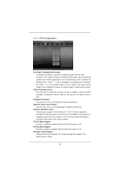
... this technology, such as Microsoft® Windows® XP / VistaTM / 7. Configuration options: [All], [1], [2] and [3]. 3.4.1 CPU Configuration Intel Hyper Threading Technology To enable this feature, it requires a computer system with an Intel processor that supports Hyper-Threading technology and an operating system that includes optimization for this item to select the...
... this technology, such as Microsoft® Windows® XP / VistaTM / 7. Configuration options: [All], [1], [2] and [3]. 3.4.1 CPU Configuration Intel Hyper Threading Technology To enable this feature, it requires a computer system with an Intel processor that supports Hyper-Threading technology and an operating system that includes optimization for this item to select the...

User Manual
Page 42
... by malicious software to execute code. Please be noted that some OS do not support this option is set to the IA-32 Intel Architecture. The default value is an enhancement to [Enabled], a VMM (Virtual Machine Architecture) can prevent data pages from overheated...to enable CPU internal thermal control mechanism to enable or disable Local x2APIC. This option will be hidden if the installed CPU does not support Intel Virtualization Technology. This option will be hidden if the current CPU does not support No-Excute Memory Protection. No-Excute Memory Protection No-Execution (...
... by malicious software to execute code. Please be noted that some OS do not support this option is set to the IA-32 Intel Architecture. The default value is an enhancement to [Enabled], a VMM (Virtual Machine Architecture) can prevent data pages from overheated...to enable CPU internal thermal control mechanism to enable or disable Local x2APIC. This option will be hidden if the installed CPU does not support Intel Virtualization Technology. This option will be hidden if the current CPU does not support No-Excute Memory Protection. No-Excute Memory Protection No-Execution (...
User Manual
Page 43
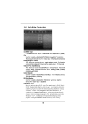
... an architecture that offers breakthrough performance for Directed I/O). The default value is [64MB]. Onboard VGA Share Memory This allows you to enable or disable Intel® VT-d technology (Intel® Virtualization Technology for the motherboard through efficient memory utilization. 3.4.2 North Bridge Configuration Low MMIO Align Low MMIO resources align at...
... an architecture that offers breakthrough performance for Directed I/O). The default value is [64MB]. Onboard VGA Share Memory This allows you to enable or disable Intel® VT-d technology (Intel® Virtualization Technology for the motherboard through efficient memory utilization. 3.4.2 North Bridge Configuration Low MMIO Align Low MMIO resources align at...

Quick Installation Guide
Page 2
...IN PCI Express 2.0 PWR_FAN1 LAN PHY 5 22 PCIE1 AUDIO CODEC Super I/O CLRCMOS1 1 CMOS 21 Battery 20 PCIE2 Intel 6 H61 32Mb BIOS 7 HD_AUDIO1 1 1 LPT1 USB8_9 1 SATA2_3 SATA2_1 SPEAKER1 1 CHA_FAN1 8 COM1 USB6_7 PLED PWRBTN ...CPU_FAN1) 4 ATX Power Connector (ATXPWR1) 5 2 x 240-pin DDR3 DIMM Slots (Dual Channel: DDR3_A1, DDR3_B1, Blue) 6 Intel H61 Chipset 7 32Mb SPI Flash 8 SATA2 Connector (SATA2_1, Blue) 9 Chassis Fan Connector (CHA_FAN1) 10 SATA2 Connector (SATA2_0, ... (PCIE1, Blue) 23 Power Fan Connector (PWR_FAN1) 2 ASRock H61M-HVGS / H61M-HVS Motherboard English
...IN PCI Express 2.0 PWR_FAN1 LAN PHY 5 22 PCIE1 AUDIO CODEC Super I/O CLRCMOS1 1 CMOS 21 Battery 20 PCIE2 Intel 6 H61 32Mb BIOS 7 HD_AUDIO1 1 1 LPT1 USB8_9 1 SATA2_3 SATA2_1 SPEAKER1 1 CHA_FAN1 8 COM1 USB6_7 PLED PWRBTN ...CPU_FAN1) 4 ATX Power Connector (ATXPWR1) 5 2 x 240-pin DDR3 DIMM Slots (Dual Channel: DDR3_A1, DDR3_B1, Blue) 6 Intel H61 Chipset 7 32Mb SPI Flash 8 SATA2 Connector (SATA2_1, Blue) 9 Chassis Fan Connector (CHA_FAN1) 10 SATA2 Connector (SATA2_0, ... (PCIE1, Blue) 23 Power Fan Connector (PWR_FAN1) 2 ASRock H61M-HVGS / H61M-HVS Motherboard English
Quick Installation Guide
Page 6
... with HDMI port - Supports Hyper-Threading Technology (see CAUTION 4) - Max. Supports Wake-On-LAN English 6 ASRock H61M-HVGS / H61M-HVS Motherboard Intel® HD Graphics 2000/3000 - 1.2 Specifications Platform CPU Chipset Memory Expansion Slot Graphics Audio LAN... - H61M-HVGS Realtek PCIE x1 Gigabit LAN RTL8111E, speed 10/100/1000 Mb/s - Intel® H61 - resolution up to 2048x1536 @ 75Hz - Supports Blu-ray Stereoscopic 3D with...
... with HDMI port - Supports Hyper-Threading Technology (see CAUTION 4) - Max. Supports Wake-On-LAN English 6 ASRock H61M-HVGS / H61M-HVS Motherboard Intel® HD Graphics 2000/3000 - 1.2 Specifications Platform CPU Chipset Memory Expansion Slot Graphics Audio LAN... - H61M-HVGS Realtek PCIE x1 Gigabit LAN RTL8111E, speed 10/100/1000 Mb/s - Intel® H61 - resolution up to 2048x1536 @ 75Hz - Supports Blu-ray Stereoscopic 3D with...
Quick Installation Guide
Page 9
...to adjust. Your friends then can reduce the number of your BIOS only in the support CD. 2. ASRock Instant Flash is a BIOS flash utility embedded in a user-friendly interface, which is including Hardware...key during the POST or press key to BIOS setup menu to access ASRock Instant Flash. Please check Intel® website for proper installation. 3. ASRock Extreme Tuning Utility (AXTU) is no such limitation. 4. In Fan... hard drive must use FAT32/16/12 file system. 9 ASRock H61M-HVGS / H61M-HVS Motherboard English In Overclocking, you to read the installation guide of...
...to adjust. Your friends then can reduce the number of your BIOS only in the support CD. 2. ASRock Instant Flash is a BIOS flash utility embedded in a user-friendly interface, which is including Hardware...key during the POST or press key to BIOS setup menu to access ASRock Instant Flash. Please check Intel® website for proper installation. 3. ASRock Extreme Tuning Utility (AXTU) is no such limitation. 4. In Fan... hard drive must use FAT32/16/12 file system. 9 ASRock H61M-HVGS / H61M-HVS Motherboard English In Overclocking, you to read the installation guide of...

Quick Installation Guide
Page 11
... off mode condition. According to define the power consumption for more details. 11 ASRock H61M-HVGS / H61M-HVS Motherboard English 13. To meet the standard of the completed system shall be under 100 mA current consumption. According to Intel's suggestion, the EuP ready power supply must meet EuP standard, an EuP ready motherboard...
... off mode condition. According to define the power consumption for more details. 11 ASRock H61M-HVGS / H61M-HVS Motherboard English 13. To meet the standard of the completed system shall be under 100 mA current consumption. According to Intel's suggestion, the EuP ready power supply must meet EuP standard, an EuP ready motherboard...
Quick Installation Guide
Page 12
Installation Pre-installation Precautions Take note of Intel 1155-Pin CPU, please follow the steps below. Failure to the motherboard, peripherals, and/or components. 2. erboard to the chassis, please do so may damage ... to static electricity, NEVER place your motherboard directly on the socket. Otherwise, the CPU will be seriously damaged. Whenever you handle components. 3. 2. English 12 ASRock H61M-HVGS / H61M-HVS Motherboard Load Plate Contact Array Load Lever Socket Body 1155-Pin Socket Overview Before you install motherboard components or change any bent pin on the...
Installation Pre-installation Precautions Take note of Intel 1155-Pin CPU, please follow the steps below. Failure to the motherboard, peripherals, and/or components. 2. erboard to the chassis, please do so may damage ... to static electricity, NEVER place your motherboard directly on the socket. Otherwise, the CPU will be seriously damaged. Whenever you handle components. 3. 2. English 12 ASRock H61M-HVGS / H61M-HVS Motherboard Load Plate Contact Array Load Lever Socket Body 1155-Pin Socket Overview Before you install motherboard components or change any bent pin on the...

Quick Installation Guide
Page 19
... C for the display icon identified by Intel® for High-Bandwidth Digital Content Protection, a specification developed by the number three and four. 6. Due to the increase in manufacturers employing HDCP in their equipment, it is compatible. 19 ASRock H61M-HVGS / H61M-HVS Motherboard English Click the items "This is HDCP? Use...
... C for the display icon identified by Intel® for High-Bandwidth Digital Content Protection, a specification developed by the number three and four. 6. Due to the increase in manufacturers employing HDCP in their equipment, it is compatible. 19 ASRock H61M-HVGS / H61M-HVS Motherboard English Click the items "This is HDCP? Use...

Quick Installation Guide
Page 114
...; Blu-ray Stereoscopic 3D 対応 - PS/2 x 1 ASRock H61M-HVGS / H61M-HVS Motherboard 日本語 H61M-HVGS Realtek PCIE x1 Gigabit LAN RTL8111E, 速度 10/100/1000 Mb/s - Micro ATX 8.9-in x 6.8-in LGA1155 パッ Intel® Turbo 2.0 K CPU 1 Intel® H61 DDR3 ( 注意 2 DDR3 DIMM x 2 - H61M-HVS Realtek PCIE x1 LAN RTL8105E, 速度 10...
...; Blu-ray Stereoscopic 3D 対応 - PS/2 x 1 ASRock H61M-HVGS / H61M-HVS Motherboard 日本語 H61M-HVGS Realtek PCIE x1 Gigabit LAN RTL8111E, 速度 10/100/1000 Mb/s - Micro ATX 8.9-in x 6.8-in LGA1155 パッ Intel® Turbo 2.0 K CPU 1 Intel® H61 DDR3 ( 注意 2 DDR3 DIMM x 2 - H61M-HVS Realtek PCIE x1 LAN RTL8105E, 速度 10...


