User Manual
Page 3
... Guide 27 2.11 Serial ATA (SATA) / Serial ATAII (SATAII) Hard Disks Installation 28 2.12 Driver Installation Guide 28 2.13 Untied Overclocking Technology 28 3 BIOS SETUP UTILITY 29 3.1 Introduction 29 3.1.1 BIOS Menu Bar 29 3.1.2 Navigation Keys 30 3.2 Main Screen 30 3.3 OC Tweaker Screen 31 3.4 Advanced Screen 35 3.4.1 CPU Configuration 36 3.4.2 Chipset Configuration 38...
... Guide 27 2.11 Serial ATA (SATA) / Serial ATAII (SATAII) Hard Disks Installation 28 2.12 Driver Installation Guide 28 2.13 Untied Overclocking Technology 28 3 BIOS SETUP UTILITY 29 3.1 Introduction 29 3.1.1 BIOS Menu Bar 29 3.1.2 Navigation Keys 30 3.2 Main Screen 30 3.3 OC Tweaker Screen 31 3.4 Advanced Screen 35 3.4.1 CPU Configuration 36 3.4.2 Chipset Configuration 38...

User Manual
Page 5
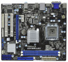
... to quality and endurance. www.asrock.com/support/index.asp 1.1 Package Contents ASRock G41MH-LE3 Motherboard (Micro ATX Form Factor: 9.6-in x 8.4-in, 24.4 cm x 21.3 cm) ASRock G41MH-LE3 Quick Installation Guide ASRock G41MH-LE3 Support CD Two Serial ATA (SATA) Data Cables (Optional) One I/O Panel Shield 5 Chapter 3 and 4 contain the configuration guide to BIOS setup and information of this manual...
... to quality and endurance. www.asrock.com/support/index.asp 1.1 Package Contents ASRock G41MH-LE3 Motherboard (Micro ATX Form Factor: 9.6-in x 8.4-in, 24.4 cm x 21.3 cm) ASRock G41MH-LE3 Quick Installation Guide ASRock G41MH-LE3 Support CD Two Serial ATA (SATA) Data Cables (Optional) One I/O Panel Shield 5 Chapter 3 and 4 contain the configuration guide to BIOS setup and information of this manual...

User Manual
Page 7
... USB 2.0 headers (support 4 USB 2.0 ports) - 8Mb AMI BIOS - O. HD Audio Jack: Line in header - AMI Legal BIOS - AMBIOS 2.3.1 Support - Drivers, Utilities, AntiVirus Software (Trial Version), ASRock Software Suite (CyberLink DVD Suite - ASRock OC Tuner (see CAUTION 7) - 1 x ATA100 IDE connector (...port header - 1 x COM port header - 1 x TPM header - ASRock Instant Flash (see CAUTION 9) - Intelligent Energy Saver (see CAUTION 10) - Supports "Plug and Play" - Rear Panel I/O Connector BIOS Feature Support CD Unique Feature I . CPU/Chassis/Power FAN connector - 24...
... USB 2.0 headers (support 4 USB 2.0 ports) - 8Mb AMI BIOS - O. HD Audio Jack: Line in header - AMI Legal BIOS - AMBIOS 2.3.1 Support - Drivers, Utilities, AntiVirus Software (Trial Version), ASRock Software Suite (CyberLink DVD Suite - ASRock OC Tuner (see CAUTION 7) - 1 x ATA100 IDE connector (...port header - 1 x COM port header - 1 x TPM header - ASRock Instant Flash (see CAUTION 9) - Intelligent Energy Saver (see CAUTION 10) - Supports "Plug and Play" - Rear Panel I/O Connector BIOS Feature Support CD Unique Feature I . CPU/Chassis/Power FAN connector - 24...

User Manual
Page 8
...DDR3 1066, DDR3 1333 1066 DDR3 800, DDR3 1066 800 DDR3 800 533 DDR3 800 * DDR3 1333 memory modules will operate in the BIOS, applying Untied Overclocking Technology, or using the thirdparty overclocking tools. Microsoft® Windows® 7 / 7 64-bit / VistaTM / ...VistaTM 64-bit / XP / XP 64-bit compliant Certifications - This motherboard supports Dual Channel Memory Technology. Hybrid Booster: - ASRock U-COP (see CAUTION 12) - CPU/Chassis/Power Fan Tachometer - Overclocking may be done at DDR3 533 if you implement Dual Channel Memory Technology,...
...DDR3 1066, DDR3 1333 1066 DDR3 800, DDR3 1066 800 DDR3 800 533 DDR3 800 * DDR3 1333 memory modules will operate in the BIOS, applying Untied Overclocking Technology, or using the thirdparty overclocking tools. Microsoft® Windows® 7 / 7 64-bit / VistaTM / ...VistaTM 64-bit / XP / XP 64-bit compliant Certifications - This motherboard supports Dual Channel Memory Technology. Hybrid Booster: - ASRock U-COP (see CAUTION 12) - CPU/Chassis/Power Fan Tachometer - Overclocking may be done at DDR3 533 if you implement Dual Channel Memory Technology,...
User Manual
Page 9
... the OC settings and share with your SATAII hard disk drive to update system BIOS without preparing an additional floppy diskette or other complicated flash utility. OC DNA, an exclusive utility developed by ASRock, provides a convenient way for the operation procedures of Intelligent Energy Saver. Frequencies ...subject to save your USB flash drive, floppy disk or hard drive, then you to change. ASRock website: http://www.asrock.com 10. With OC DNA, you can save the new BIOS file to your overclocking record under Windows® environment. In other than the recommended CPU bus...
... the OC settings and share with your SATAII hard disk drive to update system BIOS without preparing an additional floppy diskette or other complicated flash utility. OC DNA, an exclusive utility developed by ASRock, provides a convenient way for the operation procedures of Intelligent Energy Saver. Frequencies ...subject to save your USB flash drive, floppy disk or hard drive, then you to change. ASRock website: http://www.asrock.com 10. With OC DNA, you can save the new BIOS file to your overclocking record under Windows® environment. In other than the recommended CPU bus...
User Manual
Page 11
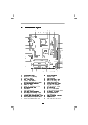
... Channel DDR3 1333 ATXPWR1 1 USB_PWR2 CPU_FAN1 6 DDR3_B1 (64 bit, 240-pin module) DDR3_A1 (64 bit, 240-pin module) HDMI1 24.4cm (9.6 in) G41MH-LE3 32 31 30 USB 2.0 T: USB0 B: USB1 Top: RJ-45 USB 2.0 T: USB2 LAN PHY B: USB3 PWR_FAN1 Intel G41 Chipset TPM1 1 7 CHA_FAN1 ...FRONT Bottom: MIC IN HD_AUDIO1 Gigabit LAN PCIE1 CMOS Battery CD1 AUDIO CODEC Super I/O 1 COM1 FLOPPY1 PCIE2 PCI1 PCI2 LPT1 1 IDE1 RoHS 8Mb BIOS IR1 1 USB4_5 1 Intel ICH7 USB6_7 1 SPEAKER1 1 USB_PWR3 1 PANEL1 PLED PWRBTN 1 HDLED RESET SATAII_1 SATAII_2 SATAII_3 SATAII_4 CLRCMOS1 1 9 10...
... Channel DDR3 1333 ATXPWR1 1 USB_PWR2 CPU_FAN1 6 DDR3_B1 (64 bit, 240-pin module) DDR3_A1 (64 bit, 240-pin module) HDMI1 24.4cm (9.6 in) G41MH-LE3 32 31 30 USB 2.0 T: USB0 B: USB1 Top: RJ-45 USB 2.0 T: USB2 LAN PHY B: USB3 PWR_FAN1 Intel G41 Chipset TPM1 1 7 CHA_FAN1 ...FRONT Bottom: MIC IN HD_AUDIO1 Gigabit LAN PCIE1 CMOS Battery CD1 AUDIO CODEC Super I/O 1 COM1 FLOPPY1 PCIE2 PCI1 PCI2 LPT1 1 IDE1 RoHS 8Mb BIOS IR1 1 USB4_5 1 Intel ICH7 USB6_7 1 SPEAKER1 1 USB_PWR3 1 PANEL1 PLED PWRBTN 1 HDLED RESET SATAII_1 SATAII_2 SATAII_3 SATAII_4 CLRCMOS1 1 9 10...
User Manual
Page 28
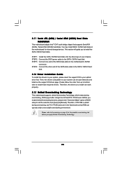
... for the possible overclocking risk before you to the SATA / SATAII hard disk. STEP 1: Install the SATA / SATAII hard disks into the drive bays of BIOS setup to set the selection from up to bottom side to [Manual]. Please follow the order from [Auto] to install those required drivers. Before you...
... for the possible overclocking risk before you to the SATA / SATAII hard disk. STEP 1: Install the SATA / SATAII hard disks into the drive bays of BIOS setup to set the selection from up to bottom side to [Manual]. Please follow the order from [Auto] to install those required drivers. Before you...

User Manual
Page 29
...they may not exactly match what you wish to get into the sub screen. 29 The SPI Memory on the system chassis. Because the BIOS software is constantly being updated, the following selections: Main To set up the system time/date information OC Tweaker To set up overclocking features... Advanced To set up the advanced BIOS features H/W Monitor To display current hardware status Boot To set up the default system device to locate and load the Operating System Security To...
...they may not exactly match what you wish to get into the sub screen. 29 The SPI Memory on the system chassis. Because the BIOS software is constantly being updated, the following selections: Main To set up the system time/date information OC Tweaker To set up overclocking features... Advanced To set up the advanced BIOS features H/W Monitor To display current hardware status Boot To set up the default system device to locate and load the Operating System Security To...

User Manual
Page 30
...Keys Please check the following table for all the settings To save changes and exit the BIOS SETUP UTILITY To jump to the Exit Screen or exit the current screen 3.2 Main Screen When you enter the BIOS SETUP UTILITY, the Main screen will appear and display the system overview... UTILITY Main OC Tweaker Advanced H/W Monitor Boot Security Exit System Overview System Time System Date [14:00:09] [Thu 05/13/2010] BIOS Version : G41MH-LE3 P1.00 Processor Type : Intel (R) Pentium (R) Dual CPU E2220 @ 2.40GHz (64bit) Processor Speed : 2400MHz Microcode Update : 6FB/A3 Cache Size : 1024KB ...
...Keys Please check the following table for all the settings To save changes and exit the BIOS SETUP UTILITY To jump to the Exit Screen or exit the current screen 3.2 Main Screen When you enter the BIOS SETUP UTILITY, the Main screen will appear and display the system overview... UTILITY Main OC Tweaker Advanced H/W Monitor Boot Security Exit System Overview System Time System Date [14:00:09] [Thu 05/13/2010] BIOS Version : G41MH-LE3 P1.00 Processor Type : Intel (R) Pentium (R) Dual CPU E2220 @ 2.40GHz (64bit) Processor Speed : 2400MHz Microcode Update : 6FB/A3 Cache Size : 1024KB ...

User Manual
Page 31
... General Help F9 Load Defaults F10 Save and Exit ESC Exit v02.54 (C) Copyright 1985-2005, American Megatrends, Inc. Configurationoptions: [1N], [2N] and [Auto]. 31 BIOS SETUP UTILITY Main OC Tweaker Advanced H/W Monitor Boot Security Exit OC Tweaker Settings Load CPU EZ OC Setting [Disabled] DRAM Frequency DRAM Command Rate DRAM...
... General Help F9 Load Defaults F10 Save and Exit ESC Exit v02.54 (C) Copyright 1985-2005, American Megatrends, Inc. Configurationoptions: [1N], [2N] and [Auto]. 31 BIOS SETUP UTILITY Main OC Tweaker Advanced H/W Monitor Boot Security Exit OC Tweaker Settings Load CPU EZ OC Setting [Disabled] DRAM Frequency DRAM Command Rate DRAM...

User Manual
Page 32
... value is [Auto]. Min: 2. Max: 15. The default value is [Auto]. DRAM tRFC This controls the number of DRAM clocks for TRCD. DRAM Timing Configuration BIOS SETUP UTILITY OC Tweaker DRAM Timing Control DRAM tCL 6 DRAM tRCD 6 DRAM tRP 6 DRAM tRAS 15 DRAM tRFC 44 DRAM tWR 6 DRAM tWTR 4 DRAM tRRD...
... value is [Auto]. Min: 2. Max: 15. The default value is [Auto]. DRAM tRFC This controls the number of DRAM clocks for TRCD. DRAM Timing Configuration BIOS SETUP UTILITY OC Tweaker DRAM Timing Control DRAM tCL 6 DRAM tRCD 6 DRAM tRP 6 DRAM tRAS 15 DRAM tRFC 44 DRAM tWR 6 DRAM tWTR 4 DRAM tRRD...

User Manual
Page 35
..., Inc. CPU Configuration Chipset Configuration ACPI Configuration Storage Configuration PCIPnP Configuration Floppy Configuration SuperIO Configuration USB Configuration BIOS Update Utility ASRock Instant Flash Select Screen Select Item Enter Go to malfunction. 35 Setting wrong values in below sections may cause... system to malfunction. BIOS SETUP UTILITY Main OC Tweaker Advanced H/W Monitor Boot Security Exit Advanced Settings Options for the ...
..., Inc. CPU Configuration Chipset Configuration ACPI Configuration Storage Configuration PCIPnP Configuration Floppy Configuration SuperIO Configuration USB Configuration BIOS Update Utility ASRock Instant Flash Select Screen Select Item Enter Go to malfunction. 35 Setting wrong values in below sections may cause... system to malfunction. BIOS SETUP UTILITY Main OC Tweaker Advanced H/W Monitor Boot Security Exit Advanced Settings Options for the ...

User Manual
Page 36
... Mode. Ratio Status This is unlocked, you will find this item appear to allow you changing the ratio value of Untied Overclocking Technology. 3.4.1 CPU Configuration BIOS SETUP UTILITY Advanced CPU Configuration Overclock Mode CPU Frequency (MHz) PCIE Frequency (MHz) Boot Failure Guard Boot Failure Guard Count Spread Spectrum [Auto] [200] [100...
... Mode. Ratio Status This is unlocked, you will find this item appear to allow you changing the ratio value of Untied Overclocking Technology. 3.4.1 CPU Configuration BIOS SETUP UTILITY Advanced CPU Configuration Overclock Mode CPU Frequency (MHz) PCIE Frequency (MHz) Boot Failure Guard Boot Failure Guard Count Spread Spectrum [Auto] [200] [100...

User Manual
Page 38
DRAM RCOMP and tRD Configuration BIOS SETUP UTILITY Advanced DRAM RCOMP STRENGTH Settings DRAM CH0 RCOMP STRENGTH Info : 54-0-11-6-6-6-6 DRAM CH0 RCOMP ODT DRAM CH0 G0 (Data) DRAM CH0 G1 (... number of DRAM CH0 RCOMP ODT. DRAM CH0 RCOMP ODT This controls the number of DRAM CH0 G0 (Data). Max: 63. Max: 15. 3.4.2 Chipset Configuration BIOS SETUP UTILITY Advanced Chipset Settings DRAM RCOMP and tRD Configuration DRAM DLL SKEW Configuration Fixed Mode Operation [Enabled] Intelligent Energy Saver Primary Graphics Adapter Shared...
DRAM RCOMP and tRD Configuration BIOS SETUP UTILITY Advanced DRAM RCOMP STRENGTH Settings DRAM CH0 RCOMP STRENGTH Info : 54-0-11-6-6-6-6 DRAM CH0 RCOMP ODT DRAM CH0 G0 (Data) DRAM CH0 G1 (... number of DRAM CH0 RCOMP ODT. DRAM CH0 RCOMP ODT This controls the number of DRAM CH0 G0 (Data). Max: 63. Max: 15. 3.4.2 Chipset Configuration BIOS SETUP UTILITY Advanced Chipset Settings DRAM RCOMP and tRD Configuration DRAM DLL SKEW Configuration Fixed Mode Operation [Enabled] Intelligent Energy Saver Primary Graphics Adapter Shared...

User Manual
Page 40
... controls the number of DRAM CH0 CMD SKEW. DRAM CH0 CLKSET1 SKEW This controls the number of DRAM CH0 CTRL3 SKEW. DRAM DLL SKEW Configuration BIOS SETUP UTILITY Advanced DRAM DLL SKEW Settings DRAM CH0 CLKSET0 SKEW Info:0-0-0-0-0-0 DRAM CH0 CLKSET0 SKEW [Auto] DRAM CH0 CLKSET1 SKEW Info:0-0-0-0-0-0 DRAM CH0 CLKSET1...
... controls the number of DRAM CH0 CMD SKEW. DRAM CH0 CLKSET1 SKEW This controls the number of DRAM CH0 CTRL3 SKEW. DRAM DLL SKEW Configuration BIOS SETUP UTILITY Advanced DRAM DLL SKEW Settings DRAM CH0 CLKSET0 SKEW Info:0-0-0-0-0-0 DRAM CH0 CLKSET0 SKEW [Auto] DRAM CH0 CLKSET1 SKEW Info:0-0-0-0-0-0 DRAM CH0 CLKSET1...

User Manual
Page 41
... options: [Enabled] and [Disabled]. Share Memory This allows you want to enable or disable flex mode operation feature. The default value is [Auto]. Besides the BIOS option, you to enable this item to [Enabled]. Configuration options: [Auto], [32MB], [64MB], [128MB] and [256MB]. The default value is [Auto]. PAVP Mode Use this...
... options: [Enabled] and [Disabled]. Share Memory This allows you want to enable or disable flex mode operation feature. The default value is [Auto]. Besides the BIOS option, you to enable this item to [Enabled]. Configuration options: [Auto], [32MB], [64MB], [128MB] and [256MB]. The default value is [Auto]. PAVP Mode Use this...

User Manual
Page 43
... power state after an unexpected AC/Power loss. Please set this option to [Enabled] if you to boot up when the power recovers. 3.4.3 ACPI Configuration BIOS SETUP UTILITY Advanced ACPI Configuration Suspend To RAM Restore on the system from the power-soft-off mode. If [Power On] is [Disabled]. ACPI HPET...
... power state after an unexpected AC/Power loss. Please set this option to [Enabled] if you to boot up when the power recovers. 3.4.3 ACPI Configuration BIOS SETUP UTILITY Advanced ACPI Configuration Suspend To RAM Restore on the system from the power-soft-off mode. If [Power On] is [Disabled]. ACPI HPET...

User Manual
Page 44
3.4.4 Storage Configuration BIOS SETUP UTILITY Advanced Storage Configuration ATA/IDE Configuration SATAII_1 SATAII_2 SATAII_3 SATAII_4 IDE1 Master IDE1 Slave [Enhanced] [Hard Disk] [Not Detected] [Not Detected] [Not Detected] [...
3.4.4 Storage Configuration BIOS SETUP UTILITY Advanced Storage Configuration ATA/IDE Configuration SATAII_1 SATAII_2 SATAII_3 SATAII_4 IDE1 Master IDE1 Slave [Enhanced] [Hard Disk] [Not Detected] [Not Detected] [Not Detected] [...

User Manual
Page 45
... [Auto]. Block (Multi-Sector Transfer) The default value of device connected to automatically detect the hard disk drive. After selecting the hard disk information into BIOS, use a disk utility, such as MO. TYPE Use this feature is necessary so that you specify. Configuration options: [Not Installed], [Auto], [CD/DVD...; Make sure to set the PIO mode to disable the use the "Primary IDE Master" as the example in the following instruction. BIOS SETUP UTILITY Advanced Primary IDE Master Device Vendor Size LBA Mode Block Mode PIO Mode Async DMA Ultra DMA S.M.A.R.T.
... [Auto]. Block (Multi-Sector Transfer) The default value of device connected to automatically detect the hard disk drive. After selecting the hard disk information into BIOS, use a disk utility, such as MO. TYPE Use this feature is necessary so that you specify. Configuration options: [Not Installed], [Auto], [CD/DVD...; Make sure to set the PIO mode to disable the use the "Primary IDE Master" as the example in the following instruction. BIOS SETUP UTILITY Advanced Primary IDE Master Device Vendor Size LBA Mode Block Mode PIO Mode Async DMA Ultra DMA S.M.A.R.T.

User Manual
Page 46
... (C) Copyright 1985-2005, American Megatrends, Inc. PCI Latency Timer The default value is recommended to maximize the IDE hard disk data transfer rate. 3.4.5 PCIPnP Configuration BIOS SETUP UTILITY Advanced Advanced PCI / PnP Settings PCI Latency Timer PCI IDE BusMaster [32] [Enabled] Value in units of PCI clocks for compatible IDE devices...
... (C) Copyright 1985-2005, American Megatrends, Inc. PCI Latency Timer The default value is recommended to maximize the IDE hard disk data transfer rate. 3.4.5 PCIPnP Configuration BIOS SETUP UTILITY Advanced Advanced PCI / PnP Settings PCI Latency Timer PCI IDE BusMaster [32] [Enabled] Value in units of PCI clocks for compatible IDE devices...


