User Manual
Page 3
... 3.4 Advanced Screen 35 3.4.1 CPU Configuration 36 3.4.2 Chipset Configuration 38 3.4.3 ACPI Configuration 43 3.4.4 Storage Configuration 44 3.4.5 PCIPnP Configuration 46 3.4.6 Floppy Configuration 47 3.4.7 Super IO Configuration 47 3.4.8 USB Configuration 49 3.5 Hardware Health Event Monitoring Screen 50 3.6 Boot Screen 51 3.5.1 Boot Settings Configuration 51 3
... 3.4 Advanced Screen 35 3.4.1 CPU Configuration 36 3.4.2 Chipset Configuration 38 3.4.3 ACPI Configuration 43 3.4.4 Storage Configuration 44 3.4.5 PCIPnP Configuration 46 3.4.6 Floppy Configuration 47 3.4.7 Super IO Configuration 47 3.4.8 USB Configuration 49 3.5 Hardware Health Event Monitoring Screen 50 3.6 Boot Screen 51 3.5.1 Boot Settings Configuration 51 3

User Manual
Page 7
...header - 1 x COM port header - 1 x TPM header - HD Audio Jack: Line in header - Front panel audio connector - 2 x USB 2.0 headers (support 4 USB 2.0 ports) - 8Mb AMI BIOS - ASRock OC Tuner (see CAUTION 10) - CD in /Front Speaker/Microphone - 4 x SATAII 3.0 Gb/s connectors (No Support for RAID and "Hot...x VGA/DVI-D Port - 1 x HDMI Port - 4 x Ready-to-Use USB 2.0 Ports - 1 x RJ-45 LAN Port with LED (ACT/LINK LED and SPEED LED) - Drivers, Utilities, AntiVirus Software (Trial Version), ASRock Software Suite (CyberLink DVD Suite - Rear Panel I/O Connector BIOS Feature Support CD Unique ...
...header - 1 x COM port header - 1 x TPM header - HD Audio Jack: Line in header - Front panel audio connector - 2 x USB 2.0 headers (support 4 USB 2.0 ports) - 8Mb AMI BIOS - ASRock OC Tuner (see CAUTION 10) - CD in /Front Speaker/Microphone - 4 x SATAII 3.0 Gb/s connectors (No Support for RAID and "Hot...x VGA/DVI-D Port - 1 x HDMI Port - 4 x Ready-to-Use USB 2.0 Ports - 1 x RJ-45 LAN Port with LED (ACT/LINK LED and SPEED LED) - Drivers, Utilities, AntiVirus Software (Trial Version), ASRock Software Suite (CyberLink DVD Suite - Rear Panel I/O Connector BIOS Feature Support CD Unique ...
User Manual
Page 9
... the new BIOS file to your USB flash drive, floppy disk or hard drive, then you to get the best system performance under the operating system and simplifies the complicated recording process of overclocking settings. ASRock website: http://www.asrock.com 10. Just launch this tool...While CPU overheat is not recommended to update system BIOS without sacrificing computing performance. 6. The software name itself - ASRock Instant Flash is a revolutionary technology that the USB flash drive or hard drive must use FAT32/16/12 file system. 11. Please be shared and worked on ...
... the new BIOS file to your USB flash drive, floppy disk or hard drive, then you to get the best system performance under the operating system and simplifies the complicated recording process of overclocking settings. ASRock website: http://www.asrock.com 10. Just launch this tool...While CPU overheat is not recommended to update system BIOS without sacrificing computing performance. 6. The software name itself - ASRock Instant Flash is a revolutionary technology that the USB flash drive or hard drive must use FAT32/16/12 file system. 11. Please be shared and worked on ...
User Manual
Page 11
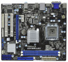
... CPU_FAN1 6 DDR3_B1 (64 bit, 240-pin module) DDR3_A1 (64 bit, 240-pin module) HDMI1 24.4cm (9.6 in) G41MH-LE3 32 31 30 USB 2.0 T: USB0 B: USB1 Top: RJ-45 USB 2.0 T: USB2 LAN PHY B: USB3 PWR_FAN1 Intel G41 Chipset TPM1 1 7 CHA_FAN1 8 1 Designed in Taipei ErP/EuP Ready... 12V Connector (ATX12V1) (SPEAKER 1, White) 3 775-Pin CPU Socket 19 USB_PWR3 Jumper 4 North Bridge Controller 20 USB 2.0 Header (USB6_7, Blue) 5 2 x 240-pin DDR3 DIMM Slots 21 USB 2.0 Header (USB4_5, Blue) (Dual Channel: DDR3_A1, DDR3_B1; Blue) 30 Front Panel Audio Header 14 Fourth SATAII Connector...
... CPU_FAN1 6 DDR3_B1 (64 bit, 240-pin module) DDR3_A1 (64 bit, 240-pin module) HDMI1 24.4cm (9.6 in) G41MH-LE3 32 31 30 USB 2.0 T: USB0 B: USB1 Top: RJ-45 USB 2.0 T: USB2 LAN PHY B: USB3 PWR_FAN1 Intel G41 Chipset TPM1 1 7 CHA_FAN1 8 1 Designed in Taipei ErP/EuP Ready... 12V Connector (ATX12V1) (SPEAKER 1, White) 3 775-Pin CPU Socket 19 USB_PWR3 Jumper 4 North Bridge Controller 20 USB 2.0 Header (USB6_7, Blue) 5 2 x 240-pin DDR3 DIMM Slots 21 USB 2.0 Header (USB4_5, Blue) (Dual Channel: DDR3_A1, DDR3_B1; Blue) 30 Front Panel Audio Header 14 Fourth SATAII Connector...

User Manual
Page 12
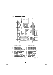
... "Stereo". 1.4 I/O Panel 1 2 3 4 5 6 11 10 9 8 7 1 PS/2 Mouse Port (Green) 2 VGA/D-Sub Port * 3 LAN RJ-45 Port 4 Line In (Light Blue) ** 5 Front Speaker (Lime) 6 Microphone (Pink) 7 USB 2.0 Ports (USB23) 8 USB 2.0 Ports (USB01) 9 HDMI Port 10 VGA/DVI-D Port 11 PS/2 Keyboard Port (Purple) * There are allowed to select "Realtek HDA Primary output" to use...
... "Stereo". 1.4 I/O Panel 1 2 3 4 5 6 11 10 9 8 7 1 PS/2 Mouse Port (Green) 2 VGA/D-Sub Port * 3 LAN RJ-45 Port 4 Line In (Light Blue) ** 5 Front Speaker (Lime) 6 Microphone (Pink) 7 USB 2.0 Ports (USB23) 8 USB 2.0 Ports (USB01) 9 HDMI Port 10 VGA/DVI-D Port 11 PS/2 Keyboard Port (Purple) * There are allowed to select "Realtek HDA Primary output" to use...

User Manual
Page 22
... is placed on CLRCMOS1 for PS/2 or USB01 wake up events. USB_PWR3 1_2 (see p.11 No. 12) 2-pin jumper Note: CLRCMOS1 allows you select +5V_DUAL, USB devices can wake up events. After waiting for USB23 wake +5V +5V_DUAL up events. Note: To select +5VSB, it requires 2 Amp and higher standby current...
... is placed on CLRCMOS1 for PS/2 or USB01 wake up events. USB_PWR3 1_2 (see p.11 No. 12) 2-pin jumper Note: CLRCMOS1 allows you select +5V_DUAL, USB devices can wake up events. After waiting for USB23 wake +5V +5V_DUAL up events. Note: To select +5VSB, it requires 2 Amp and higher standby current...

User Manual
Page 24
...(see p.11 No. 28) CD-L GND GND CD-R CD1 This is an interface for print port cable that allows convenient connection of printer devices. Each USB 2.0 header can securely store keys, digital certificates, passwords, and data. This connector allows you to receive stereo audio input from sound sources such as a... CD-ROM, DVD-ROM, TV tuner card, or MPEG card. 24 This connector supports a Trusted Platform Module (TPM) system, which can support two USB 2.0 ports. Print Port Header (25-pin LPT1) (see p.11 No. 23) TPM Header (17-pin TPM1) (see p.11 No. 7) AFD# ERROR# PINIT# SLIN# ...
...(see p.11 No. 28) CD-L GND GND CD-R CD1 This is an interface for print port cable that allows convenient connection of printer devices. Each USB 2.0 header can securely store keys, digital certificates, passwords, and data. This connector allows you to receive stereo audio input from sound sources such as a... CD-ROM, DVD-ROM, TV tuner card, or MPEG card. 24 This connector supports a Trusted Platform Module (TPM) system, which can support two USB 2.0 ports. Print Port Header (25-pin LPT1) (see p.11 No. 23) TPM Header (17-pin TPM1) (see p.11 No. 7) AFD# ERROR# PINIT# SLIN# ...

User Manual
Page 35
...: CPU Configuration, Chipset Configuration, ACPI Configuration, Storage Configuration, PCIPnP Configuration, Floppy Configuration, SuperIO Configuration, and USB Configuration. CPU Configuration Chipset Configuration ACPI Configuration Storage Configuration PCIPnP Configuration Floppy Configuration SuperIO Configuration USB Configuration BIOS Update Utility ASRock Instant Flash Select Screen Select Item Enter Go to Sub Screen F1 General Help F9 Load...
...: CPU Configuration, Chipset Configuration, ACPI Configuration, Storage Configuration, PCIPnP Configuration, Floppy Configuration, SuperIO Configuration, and USB Configuration. CPU Configuration Chipset Configuration ACPI Configuration Storage Configuration PCIPnP Configuration Floppy Configuration SuperIO Configuration USB Configuration BIOS Update Utility ASRock Instant Flash Select Screen Select Item Enter Go to Sub Screen F1 General Help F9 Load...

User Manual
Page 49
... to select [Disabled] to enable or disable USB Keyboard/Remote Power On on the system. 49 3.4.8 USB Configuration BIOS SETUP UTILITY Advanced USB Configuration USB Controller USB 2.0 Support Legacy USB Support [Enabled] [Enabled] [Enabled] USB Keyboard/Remote Power On [Disabled] USB Mouse Power On [Disabled] To enable or disable the onboard USB controllers. +F1 F9 F10 ESC Select Screen...
... to select [Disabled] to enable or disable USB Keyboard/Remote Power On on the system. 49 3.4.8 USB Configuration BIOS SETUP UTILITY Advanced USB Configuration USB Controller USB 2.0 Support Legacy USB Support [Enabled] [Enabled] [Enabled] USB Keyboard/Remote Power On [Disabled] USB Mouse Power On [Disabled] To enable or disable the onboard USB controllers. +F1 F9 F10 ESC Select Screen...
Quick Installation Guide
Page 2
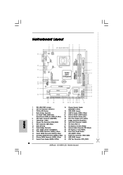
...White) 15 Secondary SATAII Connector (SATAII_2; Blue) 32 USB_PWR2 Jumper 17 System Panel Header (PANEL1, White) 33 CPU Fan Connector (CPU_FAN1) 2 ASRock G41MH-LE3 Motherboard Blue) 30 Front Panel Audio Header 14 Fourth SATAII Connector (SATAII_4; Motherboard Layout English 1 PS2_USB_PWR1 Jumper 18 Chassis Speaker Header 2 ATX ...12V Connector (ATX12V1) (SPEAKER 1, White) 3 775-Pin CPU Socket 19 USB_PWR3 Jumper 4 North Bridge Controller 20 USB 2.0 Header (USB6_7, Blue) 5 2 x 240-pin DDR3 DIMM Slots 21 USB 2.0 Header (USB4_5, Blue) (Dual Channel: DDR3_A1, DDR3_B1;
...White) 15 Secondary SATAII Connector (SATAII_2; Blue) 32 USB_PWR2 Jumper 17 System Panel Header (PANEL1, White) 33 CPU Fan Connector (CPU_FAN1) 2 ASRock G41MH-LE3 Motherboard Blue) 30 Front Panel Audio Header 14 Fourth SATAII Connector (SATAII_4; Motherboard Layout English 1 PS2_USB_PWR1 Jumper 18 Chassis Speaker Header 2 ATX ...12V Connector (ATX12V1) (SPEAKER 1, White) 3 775-Pin CPU Socket 19 USB_PWR3 Jumper 4 North Bridge Controller 20 USB 2.0 Header (USB6_7, Blue) 5 2 x 240-pin DDR3 DIMM Slots 21 USB 2.0 Header (USB4_5, Blue) (Dual Channel: DDR3_A1, DDR3_B1;

Quick Installation Guide
Page 3
...for the LAN port LED indications. Then reboot your computer, please double-click "Realtek HD Audio Manager" on your system. 3 ASRock G41MH-LE3 Motherboard English Please refer to "Quadraphonic" or "Stereo". Click "Device advanced settings", choose "Make front and rear output devices playbacks...Port (Green) 2 VGA/D-Sub Port * 3 LAN RJ-45 Port 4 Line In (Light Blue) ** 5 Front Speaker (Lime) 6 Microphone (Pink) 7 USB 2.0 Ports (USB23) 8 USB 2.0 Ports (USB01) 9 HDMI Port 10 VGA/DVI-D Port 11 PS/2 Keyboard Port (Purple) * There are allowed to select "Realtek HDA Primary output" ...
...for the LAN port LED indications. Then reboot your computer, please double-click "Realtek HD Audio Manager" on your system. 3 ASRock G41MH-LE3 Motherboard English Please refer to "Quadraphonic" or "Stereo". Click "Device advanced settings", choose "Make front and rear output devices playbacks...Port (Green) 2 VGA/D-Sub Port * 3 LAN RJ-45 Port 4 Line In (Light Blue) ** 5 Front Speaker (Lime) 6 Microphone (Pink) 7 USB 2.0 Ports (USB23) 8 USB 2.0 Ports (USB01) 9 HDMI Port 10 VGA/DVI-D Port 11 PS/2 Keyboard Port (Purple) * There are allowed to select "Realtek HDA Primary output" ...

Quick Installation Guide
Page 6
...) English 6 ASRock G41MH-LE3 Motherboard ASRock OC DNA (see CAUTION 8) - AMI Legal BIOS - Drivers, Utilities, AntiVirus Software (Trial Version), ASRock Software Suite (CyberLink DVD Suite - Intelligent Energy Saver (see CAUTION 7) - 1 x ATA100 IDE connector (supports 2 x IDE devices) - 1 x Floppy connector - 1 x IR header - 1 x Print port header - 1 x COM port header - 1 x TPM header - Front panel audio connector - 2 x USB 2.0 headers (support 4 USB 2.0 ports...
...) English 6 ASRock G41MH-LE3 Motherboard ASRock OC DNA (see CAUTION 8) - AMI Legal BIOS - Drivers, Utilities, AntiVirus Software (Trial Version), ASRock Software Suite (CyberLink DVD Suite - Intelligent Energy Saver (see CAUTION 7) - 1 x ATA100 IDE connector (supports 2 x IDE devices) - 1 x Floppy connector - 1 x IR header - 1 x Print port header - 1 x COM port header - 1 x TPM header - Front panel audio connector - 2 x USB 2.0 headers (support 4 USB 2.0 ports...

Quick Installation Guide
Page 8
... Flash is a revolutionary technology that delivers unparalleled power savings. With this utility, you install the PC system. 8 ASRock G41MH-LE3 Motherboard English The software name itself - OC DNA, an exclusive utility developed by the chipset vendor and is not recommended to surveil your system...or damage the CPU. 13. 6. Please visit our website for the latest information. 7. Although this tool and save the new BIOS file to your USB flash drive, floppy disk or hard drive, then you can also connect SATA hard disk to SATAII connector, please read the "SATAII Hard Disk Setup...
... Flash is a revolutionary technology that delivers unparalleled power savings. With this utility, you install the PC system. 8 ASRock G41MH-LE3 Motherboard English The software name itself - OC DNA, an exclusive utility developed by the chipset vendor and is not recommended to surveil your system...or damage the CPU. 13. 6. Please visit our website for the latest information. 7. Although this tool and save the new BIOS file to your USB flash drive, floppy disk or hard drive, then you can also connect SATA hard disk to SATAII connector, please read the "SATAII Hard Disk Setup...
Quick Installation Guide
Page 18
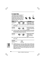
... system setup parameters. Note: To select +5VSB, it requires 2 Amp and higher standby current provided by power supply. English 18 ASRock G41MH-LE3 Motherboard USB_PWR3 Short pin2, pin3 to RAM) state. To clear and reset the system parameters to short 2 pins on CLRCMOS1 for ... seconds. Jumper Setting Description PS2_USB_PWR1 Short pin2, pin3 to enable (see p.2 No. 12) 2-pin jumper Note: CLRCMOS1 allows you select +5V_DUAL, USB devices can wake up events. After waiting for USB23 wake up the system under S3 (Suspend to enable (see p.2, No. 32) +5V_DUAL for...
... system setup parameters. Note: To select +5VSB, it requires 2 Amp and higher standby current provided by power supply. English 18 ASRock G41MH-LE3 Motherboard USB_PWR3 Short pin2, pin3 to RAM) state. To clear and reset the system parameters to short 2 pins on CLRCMOS1 for ... seconds. Jumper Setting Description PS2_USB_PWR1 Short pin2, pin3 to enable (see p.2 No. 12) 2-pin jumper Note: CLRCMOS1 allows you select +5V_DUAL, USB devices can wake up events. After waiting for USB23 wake up the system under S3 (Suspend to enable (see p.2, No. 32) +5V_DUAL for...

Quick Installation Guide
Page 20
...-ROM, DVD-ROM, TV tuner card, or MPEG card. 20 ASRock G41MH-LE3 Motherboard English This is an interface for print port cable that allows convenient connection of printer devices. This connector supports a Trusted Platform Module (TPM) system, which can support two USB 2.0 ports. USB 2.0 Headers (9-pin USB6_7) (see p.2 No. 20) (9-pin USB4_5) (see p.2 No...
...-ROM, DVD-ROM, TV tuner card, or MPEG card. 20 ASRock G41MH-LE3 Motherboard English This is an interface for print port cable that allows convenient connection of printer devices. This connector supports a Trusted Platform Module (TPM) system, which can support two USB 2.0 ports. USB 2.0 Headers (9-pin USB6_7) (see p.2 No. 20) (9-pin USB4_5) (see p.2 No...


