User Manual
Page 3
... Motherboard Layout 11 1.5 I/O Panel 12 2 Installation 13 2.1 Screw Holes 13 2.2 Pre-installation Precautions 13 2.3 CPU Installation 14 2.4 Installation of Heatsink and CPU fan 16 2.5 Installation of Memory Modules (DIMM 17 2.6 Expansion Slots (PCI and PCI Express Slots 19 2.7 ... 31 3.1.1 BIOS Menu Bar 31 3.1.2 Navigation Keys 32 3.2 Main Screen 32 3.3 Smart Screen 33 3.4 Advanced Screen 34 3.4.1 CPU Configuration 35 3.4.2 Chipset Configuration 37 3.4.3 ACPI Configuration 45 3.4.4 Storage Configuration 47 3.4.5 PCIPnP Configuration 49 3.4.6 Floppy Configuration 50 3.4.7 Super ...
... Motherboard Layout 11 1.5 I/O Panel 12 2 Installation 13 2.1 Screw Holes 13 2.2 Pre-installation Precautions 13 2.3 CPU Installation 14 2.4 Installation of Heatsink and CPU fan 16 2.5 Installation of Memory Modules (DIMM 17 2.6 Expansion Slots (PCI and PCI Express Slots 19 2.7 ... 31 3.1.1 BIOS Menu Bar 31 3.1.2 Navigation Keys 32 3.2 Main Screen 32 3.3 Smart Screen 33 3.4 Advanced Screen 34 3.4.1 CPU Configuration 35 3.4.2 Chipset Configuration 37 3.4.3 ACPI Configuration 45 3.4.4 Storage Configuration 47 3.4.5 PCIPnP Configuration 49 3.4.6 Floppy Configuration 50 3.4.7 Super ...
User Manual
Page 5
...visit our website for purchasing ASRock G41MH-GE motherboard, a reliable motherboard produced under ASRock's consistently stringent quality control. It delivers excellent performance with robust design conforming to ASRock's commitment to BIOS setup...on ASRock website as well. www.asrock.com/support/index.asp 1.1 Package Contents ASRock G41MH-GE Motherboard (Micro ATX Form Factor: 9.6-in x 9.6-in, 24.4 cm x 24.4 cm) ASRock G41MH-GE Quick Installation Guide ASRock G41MH-GE Support... notice. ASRock website http://www.asrock.com If you are using. You may find the latest VGA cards...
...visit our website for purchasing ASRock G41MH-GE motherboard, a reliable motherboard produced under ASRock's consistently stringent quality control. It delivers excellent performance with robust design conforming to ASRock's commitment to BIOS setup...on ASRock website as well. www.asrock.com/support/index.asp 1.1 Package Contents ASRock G41MH-GE Motherboard (Micro ATX Form Factor: 9.6-in x 9.6-in, 24.4 cm x 24.4 cm) ASRock G41MH-GE Quick Installation Guide ASRock G41MH-GE Support... notice. ASRock website http://www.asrock.com If you are using. You may find the latest VGA cards...

User Manual
Page 6
1.2 Specifications Platform CPU Chipset Memory Expansion Slot Graphics Audio LAN Rear Panel I /O Panel - 1 x PS/2 Mouse Port - 1 x PS/2 Keyboard Port 6 Micro ATX Form Factor: 9.6-in x 9.6-in, 24.4 cm x 24.4 .... resolution up to 1920x1200 @ 75Hz - resolution up to 2048x1536 @ 60Hz - Supports HDCP function - Supports Wake-On-LAN I /O - Supports FSB1333/1066/800/533 MHz - Supports EM64T CPU - Southbridge: Intel® ICH7 - Max. Three VGA Output options: D-Sub, DVI-D and HDMI - Supports DVI with max. Support DDR2 1066/800/667/533 non-ECC...
1.2 Specifications Platform CPU Chipset Memory Expansion Slot Graphics Audio LAN Rear Panel I /O Panel - 1 x PS/2 Mouse Port - 1 x PS/2 Keyboard Port 6 Micro ATX Form Factor: 9.6-in x 9.6-in, 24.4 cm x 24.4 .... resolution up to 1920x1200 @ 75Hz - resolution up to 2048x1536 @ 60Hz - Supports HDCP function - Supports Wake-On-LAN I /O - Supports FSB1333/1066/800/533 MHz - Supports EM64T CPU - Southbridge: Intel® ICH7 - Max. Three VGA Output options: D-Sub, DVI-D and HDMI - Supports DVI with max. Support DDR2 1066/800/667/533 non-ECC...
User Manual
Page 7
...pin 12V power connector - AMI Legal BIOS - ACPI 1.1 Compliance Wake Up Events - O. ASRock Instant Flash (see CAUTION 15) - CPU Frequency Stepless Control (see CAUTION 13) - ASRock U-COP (see CAUTION 11) - Boot Failure Guard (B.F.G.) - CD in /Front Speaker/Microphone ...No Support for RAID and "Hot Plug" functions) (see CAUTION 12) - Supports jumperfree - CPU Temperature Sensing - Drivers, Utilities, AntiVirus Software (Trial Version) - ASRock OC Tuner (see CAUTION 16) - ASRock OC DNA (see CAUTION 10) - 8Mb AMI BIOS - T. (Intelligent Overclocking Technology) - ...
...pin 12V power connector - AMI Legal BIOS - ACPI 1.1 Compliance Wake Up Events - O. ASRock Instant Flash (see CAUTION 15) - CPU Frequency Stepless Control (see CAUTION 13) - ASRock U-COP (see CAUTION 11) - Boot Failure Guard (B.F.G.) - CD in /Front Speaker/Microphone ...No Support for RAID and "Hot Plug" functions) (see CAUTION 12) - Supports jumperfree - CPU Temperature Sensing - Drivers, Utilities, AntiVirus Software (Trial Version) - ASRock OC Tuner (see CAUTION 16) - ASRock OC DNA (see CAUTION 10) - 8Mb AMI BIOS - T. (Intelligent Overclocking Technology) - ...

User Manual
Page 8
...Untied Overclocking Technology" on page 18 for details. 3. This motherboard supports Untied Overclocking Technology. This motherboard supports Dual Channel Memory Technology. CPU FSB Frequency Memory Support Frequency 1333 DDR2 667, DDR2 800, DDR2 1066 1066 DDR2 667, DDR2 800, DDR2 1066 800 DDR2 ...EuP Ready (EuP ready power supply is required) (see CAUTION 17) * For detailed product information, please visit our website: http://www.asrock.com WARNING Please realize that there is no such limitation. 6. About the setting of memory modules on page 30 for proper installation. 4....
...Untied Overclocking Technology" on page 18 for details. 3. This motherboard supports Untied Overclocking Technology. This motherboard supports Dual Channel Memory Technology. CPU FSB Frequency Memory Support Frequency 1333 DDR2 667, DDR2 800, DDR2 1066 1066 DDR2 667, DDR2 800, DDR2 1066 800 DDR2 ...EuP Ready (EuP ready power supply is required) (see CAUTION 17) * For detailed product information, please visit our website: http://www.asrock.com WARNING Please realize that there is no such limitation. 6. About the setting of memory modules on page 30 for proper installation. 4....
User Manual
Page 9
...bit / XP SP1 or SP2. 11. Featuring an advanced proprietary hardware and software design, Intelligent Energy Saver is a user-friendly ASRock overclocking tool which allows you to provide exceptional power saving and improve power efficiency without entering operating systems first like MS-DOS or..., and 8-channel modes. This convenient BIOS update tool allows you to SATAII mode. Frequencies other than the recommended CPU bus frequencies may cause the instability of ASRock OC Tuner. Please check the table on the same motherboard. 15. It is a revolutionary technology that the USB...
...bit / XP SP1 or SP2. 11. Featuring an advanced proprietary hardware and software design, Intelligent Energy Saver is a user-friendly ASRock overclocking tool which allows you to provide exceptional power saving and improve power efficiency without entering operating systems first like MS-DOS or..., and 8-channel modes. This convenient BIOS update tool allows you to SATAII mode. Frequencies other than the recommended CPU bus frequencies may cause the instability of ASRock OC Tuner. Please check the table on the same motherboard. 15. It is a revolutionary technology that the USB...

User Manual
Page 10
...remember to define the power consumption for Energy Using Product, was a provision regulated by European Union to spray thermal grease between the CPU and the heatsink when you install the PC system. 17. EuP, stands for the completed system. For EuP ready power supply ... 64-bit) CyberLink PowerDVD9 with the power supply manufacturer for more details. 1 . 3 Minimum Hardware Requirement for the minimum hardware requirement. While CPU overheat is higher than 50% under 1.00W in off mode condition. According to Intel's suggestion, the EuP ready power supply must meet EuP standard...
...remember to define the power consumption for Energy Using Product, was a provision regulated by European Union to spray thermal grease between the CPU and the heatsink when you install the PC system. 17. EuP, stands for the completed system. For EuP ready power supply ... 64-bit) CyberLink PowerDVD9 with the power supply manufacturer for more details. 1 . 3 Minimum Hardware Requirement for the minimum hardware requirement. While CPU overheat is higher than 50% under 1.00W in off mode condition. According to Intel's suggestion, the EuP ready power supply must meet EuP standard...

User Manual
Page 11
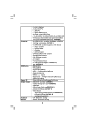
...64 bit, 240-pin module) DDRII_1 (64 bit, 240-pin module) RoHS FSB1333 HDMI1 SPDIF_O1 30 1 IR1 USB 2.0 T: USB2 B: USB3 PWR_FAN1 IDE1 G41MH-GE USB 2.0 T: USB0 B: USB1 Top: RJ-45 Top: SIDE SPK Center: REAR SPK Bottom: CTR BASS Top: LINE IN Center: FRONT Bottom: ...PS2_USB_PWR1 Jumper 17 USB 2.0 Header (USB4_5, Blue) 2 ATX 12V Connector (ATX12V1) 18 Chassis Fan Connector (CHA_FAN1) 3 CPU Fan Connector (CPU_FAN1) 19 System Panel Header (PANEL1, Orange) 4 775-Pin CPU Socket 20 Print Port Header (LPT1, Purple) 5 2 x 240-pin DDR2 DIMM Slots 21 Chassis Speaker Header (Dual ...
...64 bit, 240-pin module) DDRII_1 (64 bit, 240-pin module) RoHS FSB1333 HDMI1 SPDIF_O1 30 1 IR1 USB 2.0 T: USB2 B: USB3 PWR_FAN1 IDE1 G41MH-GE USB 2.0 T: USB0 B: USB1 Top: RJ-45 Top: SIDE SPK Center: REAR SPK Bottom: CTR BASS Top: LINE IN Center: FRONT Bottom: ...PS2_USB_PWR1 Jumper 17 USB 2.0 Header (USB4_5, Blue) 2 ATX 12V Connector (ATX12V1) 18 Chassis Fan Connector (CHA_FAN1) 3 CPU Fan Connector (CPU_FAN1) 19 System Panel Header (PANEL1, Orange) 4 775-Pin CPU Socket 20 Print Port Header (LPT1, Purple) 5 2 x 240-pin DDR2 DIMM Slots 21 Chassis Speaker Header (Dual ...

User Manual
Page 15
... the socket: Step 1-1. Orient the CPU with black lines. Step 1-2. Insert the 775-LAND CPU: Step 2-1. Step 2-2. Locate Pin1 and the two orientation key notches. Rotate the load lever to insert the CPU into the socket, please check if the CPU surface is unclean or if there is...with IHS (Integrated Heat Sink) up. Step 2. Hold the CPU by depressing down and out on the socket. Otherwise, the CPU will be seriously damaged. Step 1. Step 1-3. 2.3 CPU Installation For the installation of Intel 775-LAND CPU, please follow the steps below. 775-Pin Socket Overview Before ...
... the socket: Step 1-1. Orient the CPU with black lines. Step 1-2. Insert the 775-LAND CPU: Step 2-1. Step 2-2. Locate Pin1 and the two orientation key notches. Rotate the load lever to insert the CPU into the socket, please check if the CPU surface is unclean or if there is...with IHS (Integrated Heat Sink) up. Step 2. Hold the CPU by depressing down and out on the socket. Otherwise, the CPU will be seriously damaged. Step 1. Step 1-3. 2.3 CPU Installation For the installation of Intel 775-LAND CPU, please follow the steps below. 775-Pin Socket Overview Before ...

User Manual
Page 16
Verify that the CPU is recommended to use the cap tab to handle and avoid kicking off the PnP cap. 2. Remove PnP... right hand thumb and peel the cap from the socket while pressing on load plate, engage the load lever. Carefully place the CPU into the socket by using a purely vertical motion. Secure load lever with the two alignment keys of load lever. 16 Step... 2-4. It is within the socket and properly mated to match the two orientation key notches of the CPU with load plate tab under retention tab of the socket. Rotate the load plate onto the IHS. Step 4. Step 4-3. Step 2-3.
Verify that the CPU is recommended to use the cap tab to handle and avoid kicking off the PnP cap. 2. Remove PnP... right hand thumb and peel the cap from the socket while pressing on load plate, engage the load lever. Carefully place the CPU into the socket by using a purely vertical motion. Secure load lever with the two alignment keys of load lever. 16 Step... 2-4. It is within the socket and properly mated to match the two orientation key notches of the CPU with load plate tab under retention tab of the socket. Rotate the load plate onto the IHS. Step 4. Step 4-3. Step 2-3.

User Manual
Page 17
... without rotating them clockwise, the heatsink cannot be secured on the socket surface. Step 5. Step 6. Below is equipped with Intel 775-LAND CPU to dissipate heat. Step 2. Repeat with fan operation or contact other . Before you installed the heatsink, you press down on fastener caps ...with the motherboard throughholes. Secure excess cable with tie-wrap to ensure cable does not interfere with remaining fasteners. Then connect the CPU fan to the CPU_FAN connector (CPU_FAN1, see page 11, No. 3). Connect fan header with each other components. 17 Step 1. Ensure fan...
... without rotating them clockwise, the heatsink cannot be secured on the socket surface. Step 5. Step 6. Below is equipped with Intel 775-LAND CPU to dissipate heat. Step 2. Repeat with fan operation or contact other . Before you installed the heatsink, you press down on fastener caps ...with the motherboard throughholes. Secure excess cable with tie-wrap to ensure cable does not interfere with remaining fasteners. Then connect the CPU fan to the CPU_FAN connector (CPU_FAN1, see page 11, No. 3). Connect fan header with each other components. 17 Step 1. Ensure fan...
User Manual
Page 27
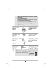
... Fan Connectors (3-pin CHA_FAN1) (see p.11 No. 18) GND +12V CHA_FAN_SPEED (3-pin PWR_FAN1) (see p.11 No. 3) Please connect a CPU fan cable 1 GND 2 +12V to this connector and match 3 CPU_FAN_SPEED 4 FAN_SPEED_CONTROL the black wire to this header. Please connect the chassis ...speaker to the ground pin. CPU Fan Connector (4-pin CPU_FAN1) (see p.11 No. 31) PWR_FAN_SPEED +12V GND This header accommodates several system front panel functions. Enter...
... Fan Connectors (3-pin CHA_FAN1) (see p.11 No. 18) GND +12V CHA_FAN_SPEED (3-pin PWR_FAN1) (see p.11 No. 3) Please connect a CPU fan cable 1 GND 2 +12V to this connector and match 3 CPU_FAN_SPEED 4 FAN_SPEED_CONTROL the black wire to this header. Please connect the chassis ...speaker to the ground pin. CPU Fan Connector (4-pin CPU_FAN1) (see p.11 No. 31) PWR_FAN_SPEED +12V GND This header accommodates several system front panel functions. Enter...
User Manual
Page 30
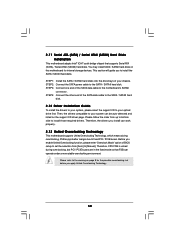
Therefore, CPU FSB is untied during overclocking, FSB enjoys better margin due to your chassis. This section will guide you install can work properly. 2.13 Untied Overclocking ...
Therefore, CPU FSB is untied during overclocking, FSB enjoys better margin due to your chassis. This section will guide you install can work properly. 2.13 Untied Overclocking ...

User Manual
Page 32
... UTILITY Main Smart Advanced H/W Monitor Boot Security Exit System Overview System Time System Date [14:00:09] [Mon 09/21/2008] BIOS Version : G41MH-GE P1.00 Processor Type : Intel(R) CPU 3.20GHz (64bit) Processor Speed : 3200MHz Microcode Update : F64/4 Cache Size : 4096KB Total Memory DDRII1 DDRII2 DDRII3 DDRII4 : 1024MB with 128MB shared memory...
... UTILITY Main Smart Advanced H/W Monitor Boot Security Exit System Overview System Time System Date [14:00:09] [Mon 09/21/2008] BIOS Version : G41MH-GE P1.00 Processor Type : Intel(R) CPU 3.20GHz (64bit) Processor Speed : 3200MHz Microcode Update : F64/4 Cache Size : 4096KB Total Memory DDRII1 DDRII2 DDRII3 DDRII4 : 1024MB with 128MB shared memory...
User Manual
Page 34
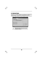
Setting wrong values in below sections may cause system to malfunction. Options for the following items: CPU Configuration, Chipset Configuration, ACPI Configuration, Storage Configuration, PCIPnP Configuration, Floppy Configuration, SuperIO Configuration, and ...Monitor Boot Security Exit Advanced Settings WARNING : Setting wrong values in this section, you may set the configurations for CPU CPU Configuration Chipset Configuration ACPI Configuration Storage Configuration PCIPnP Configuration Floppy Configuration SuperIO Configuration USB Configuration Select Screen Select Item Enter ...
Setting wrong values in below sections may cause system to malfunction. Options for the following items: CPU Configuration, Chipset Configuration, ACPI Configuration, Storage Configuration, PCIPnP Configuration, Floppy Configuration, SuperIO Configuration, and ...Monitor Boot Security Exit Advanced Settings WARNING : Setting wrong values in this section, you may set the configurations for CPU CPU Configuration Chipset Configuration ACPI Configuration Storage Configuration PCIPnP Configuration Floppy Configuration SuperIO Configuration USB Configuration Select Screen Select Item Enter ...
User Manual
Page 35
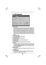
...Frequency (MHz) Use this motherboard. Ratio Actual Value This is "Locked" or "Unlocked". Overclock Mode Use this option to adjust CPU frequency. Configuration options: [Auto], [Manual], [I .O.T.] (Intelligent Overclocking Technology), the system will find an item Ratio CMOS Setting appears... allowed to adjust PCIE frequency. If you select [I .O.T.] and [Optimized]. Ratio Status This is [Auto]. 3.4.1 CPU Configuration BIOS SETUP UTILITY Advanced CPU Configuration Overclock Mode CPU Frequency (MHz) PCIE Frequency (MHz) Boot Failure Guard Spread Spectrum [Auto] [200] [100] [Enabled] [...
...Frequency (MHz) Use this motherboard. Ratio Actual Value This is "Locked" or "Unlocked". Overclock Mode Use this option to adjust CPU frequency. Configuration options: [Auto], [Manual], [I .O.T.] (Intelligent Overclocking Technology), the system will find an item Ratio CMOS Setting appears... allowed to adjust PCIE frequency. If you select [I .O.T.] and [Optimized]. Ratio Status This is [Auto]. 3.4.1 CPU Configuration BIOS SETUP UTILITY Advanced CPU Configuration Overclock Mode CPU Frequency (MHz) PCIE Frequency (MHz) Boot Failure Guard Spread Spectrum [Auto] [200] [100] [Enabled] [...

User Manual
Page 36
...through the native processor instructions HLT and MWAIT and requires no hardware support from overheated. This option will be hidden if the current CPU does not support No-Excute Memory Protection. Hyper Threading Technology To enable this item to enable powersavings. is [Auto]. Configuration options...: [Auto], [Enabled] and [Disabled]. This item will be hidden if the current CPU does not support Intel (R) SpeedStep(tm) tech.. The C1 state is an enhancement to [Enabled], a VMM (Virtual Machine Architecture) can ...
...through the native processor instructions HLT and MWAIT and requires no hardware support from overheated. This option will be hidden if the current CPU does not support No-Excute Memory Protection. Hyper Threading Technology To enable this item to enable powersavings. is [Auto]. Configuration options...: [Auto], [Enabled] and [Disabled]. This item will be hidden if the current CPU does not support Intel (R) SpeedStep(tm) tech.. The C1 state is an enhancement to [Enabled], a VMM (Virtual Machine Architecture) can ...
User Manual
Page 37
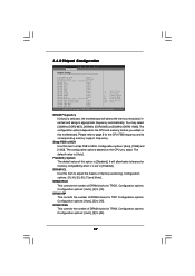
... adjust the means of DRAM clocks for TRAS. Strap FSB to MCH Use this motherboard. Flexibility Option The default value of DRAM clocks for the CPU FSB frequency and its corresponding memory support frequency. You may select [333MHz (DDR2 667)], [400MHz (DDR2 800)] or [533MHz (DDR2 1066)]. DRAM ...[Enabled]. DRAM tRAS This controls the number of DRAM clocks for TRP. Configuration options: [Auto], [1066] and [1333]. The configuration options depend on the CPU you adopt on the CPU and memory module you adopt. Configuration options: [3], [4], [5], [6], [7] and [Auto].
... adjust the means of DRAM clocks for TRAS. Strap FSB to MCH Use this motherboard. Flexibility Option The default value of DRAM clocks for the CPU FSB frequency and its corresponding memory support frequency. You may select [333MHz (DDR2 667)], [400MHz (DDR2 800)] or [533MHz (DDR2 1066)]. DRAM ...[Enabled]. DRAM tRAS This controls the number of DRAM clocks for TRP. Configuration options: [Auto], [1066] and [1333]. The configuration options depend on the CPU you adopt on the CPU and memory module you adopt. Configuration options: [3], [4], [5], [6], [7] and [Auto].

User Manual
Page 43
... Select [Auto], [Enabled] or [Disabled] for the onboard HD Audio Front Panel. Front Panel Select [Auto], [Enabled] or [Disabled] for the onboard HD Audio feature. CPU Voltage Use this option to support increased content protection and robustness requirements for premium content playback (Blu-ray disc). [Lite] mode is plugged. Configuration options...
... Select [Auto], [Enabled] or [Disabled] for the onboard HD Audio Front Panel. Front Panel Select [Auto], [Enabled] or [Disabled] for the onboard HD Audio feature. CPU Voltage Use this option to support increased content protection and robustness requirements for premium content playback (Blu-ray disc). [Lite] mode is plugged. Configuration options...

User Manual
Page 53
...Monitoring Screen In this section, it allows you to monitor the status of the hardware on your system, including the parameters of CPU fan. F1 F9 F10 ESC Select Screen Select Item General Help Load Defaults Save and Exit Exit v02.54 (C) Copyright 1985-...6] [Level 7], [Level 8] and [Level 9]. 53 BIOS SETUP UTILITY Main Smart Advanced H/W Monitor Boot Security Exit Hardware Health Event Monitoring CPU Temperature M / B Temperature CPU Fan Speed Chassis Fan Speed Power Fan Speed Vcore + 3.30V + 5.00V + 12.00V CPU Quiet Fan : 37 C / 98 F : 27 C / 80 F : 4722 RPM : N/A : N/A : 1.216V : 3.248V...
...Monitoring Screen In this section, it allows you to monitor the status of the hardware on your system, including the parameters of CPU fan. F1 F9 F10 ESC Select Screen Select Item General Help Load Defaults Save and Exit Exit v02.54 (C) Copyright 1985-...6] [Level 7], [Level 8] and [Level 9]. 53 BIOS SETUP UTILITY Main Smart Advanced H/W Monitor Boot Security Exit Hardware Health Event Monitoring CPU Temperature M / B Temperature CPU Fan Speed Chassis Fan Speed Power Fan Speed Vcore + 3.30V + 5.00V + 12.00V CPU Quiet Fan : 37 C / 98 F : 27 C / 80 F : 4722 RPM : N/A : N/A : 1.216V : 3.248V...


