User Manual
Page 3
...Contents 5 1.2 Specifications 6 1.3 Motherboard Layout (G41M-VGS3 / G41M-VS3) ......... 11 1.4 I/O Panel (G41M-VGS3 12 1.5 I/O Panel (G41M-VS3 13 2 Installation 14 2.1 Screw Holes 14 2.2 Pre-installation Precautions 14 2.3 CPU Installation 15 2.4 Installation of Heatsink and CPU fan 17 2.5 Installation of Memory Modules (... Bar 26 3.1.2 Navigation Keys 27 3.2 Main Screen 27 3.3 OC Tweaker Screen 29 3.4 Advanced Screen 32 3.4.1 CPU Configuration 33 3.4.2 Chipset Configuration 35 3.4.3 ACPI Configuration 41 3.4.4 Storage Configuration 42 3.4.5 PCIPnP Configuration 44 3.4.6 Super...
...Contents 5 1.2 Specifications 6 1.3 Motherboard Layout (G41M-VGS3 / G41M-VS3) ......... 11 1.4 I/O Panel (G41M-VGS3 12 1.5 I/O Panel (G41M-VS3 13 2 Installation 14 2.1 Screw Holes 14 2.2 Pre-installation Precautions 14 2.3 CPU Installation 15 2.4 Installation of Heatsink and CPU fan 17 2.5 Installation of Memory Modules (... Bar 26 3.1.2 Navigation Keys 27 3.2 Main Screen 27 3.3 OC Tweaker Screen 29 3.4 Advanced Screen 32 3.4.1 CPU Configuration 33 3.4.2 Chipset Configuration 35 3.4.3 ACPI Configuration 41 3.4.4 Storage Configuration 42 3.4.5 PCIPnP Configuration 44 3.4.6 Super...
User Manual
Page 5
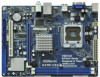
.../support/index.asp 1.1 Package Contents ASRock G41M-VGS3 / G41M-VS3 Motherboard (Micro ATX Form Factor: 8.9-in x 6.7-in, 22.6 cm x 17.0 cm) ASRock G41M-VGS3 / G41M-VS3 Quick Installation Guide ASRock G41M-VGS3 / G41M-VS3 Support CD Two Serial ATA (SATA) Data Cables (Optional) One I/O Panel Shield 5 Because the ... to change without further notice. You may find the latest VGA cards and CPU support lists on ASRock website without notice. It delivers excellent performance with robust design conforming to ASRock's commitment to quality and endurance. In this manual, chapter 1 and 2 contain...
.../support/index.asp 1.1 Package Contents ASRock G41M-VGS3 / G41M-VS3 Motherboard (Micro ATX Form Factor: 8.9-in x 6.7-in, 22.6 cm x 17.0 cm) ASRock G41M-VGS3 / G41M-VS3 Quick Installation Guide ASRock G41M-VGS3 / G41M-VS3 Support CD Two Serial ATA (SATA) Data Cables (Optional) One I/O Panel Shield 5 Because the ... to change without further notice. You may find the latest VGA cards and CPU support lists on ASRock website without notice. It delivers excellent performance with robust design conforming to ASRock's commitment to quality and endurance. In this manual, chapter 1 and 2 contain...
User Manual
Page 6
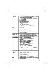
...to -Use USB 2.0 Ports - 1 x RJ-45 LAN Port with max. G41M-VGS3 Atheros® PCIE x1 Gigabit LAN AR8151, speed 10/100/1000 Mb/s - G41M-VS3 Atheros® PCIE x1 LAN AR8152, speed 10/100 Mb/s - Supports Hyper-...Threading Technology (see CAUTION 4) - capacity of system memory: 8GB (see CAUTION 6) - shared memory 1759MB (see CAUTION 5) - 1 x PCI Express x16 slot - 1 x PCI slot - Northbridge: Intel® G41 - Intel® Graphics Media Accelerator X4500 - 1.2 Specifications Platform CPU...
...to -Use USB 2.0 Ports - 1 x RJ-45 LAN Port with max. G41M-VGS3 Atheros® PCIE x1 Gigabit LAN AR8151, speed 10/100/1000 Mb/s - G41M-VS3 Atheros® PCIE x1 LAN AR8152, speed 10/100 Mb/s - Supports Hyper-...Threading Technology (see CAUTION 4) - capacity of system memory: 8GB (see CAUTION 6) - shared memory 1759MB (see CAUTION 5) - 1 x PCI Express x16 slot - 1 x PCI slot - Northbridge: Intel® G41 - Intel® Graphics Media Accelerator X4500 - 1.2 Specifications Platform CPU...
User Manual
Page 7
...; 7 / 7 64-bit / VistaTM / VistaTM 64-bit / XP / XP 64-bit compliant 7 Creative Sound Blaster X-Fi MB - ASRock OC DNA (see CAUTION 11) - Boot Failure Guard (B.F.G.) - ASRock Instant Flash (see CAUTION 12) - SmartView (see CAUTION 13) - CPU Temperature Sensing - ASRock AIWI (see CAUTION 15) - Front panel audio connector - 2 x USB 2.0 headers (support 4 USB 2.0 ports) (see CAUTION...
...; 7 / 7 64-bit / VistaTM / VistaTM 64-bit / XP / XP 64-bit compliant 7 Creative Sound Blaster X-Fi MB - ASRock OC DNA (see CAUTION 11) - Boot Failure Guard (B.F.G.) - ASRock Instant Flash (see CAUTION 12) - SmartView (see CAUTION 13) - CPU Temperature Sensing - ASRock AIWI (see CAUTION 15) - Front panel audio connector - 2 x USB 2.0 headers (support 4 USB 2.0 ports) (see CAUTION...
User Manual
Page 8
...Untied Overclocking Technology. Overclocking may be done at DDR3 533 if you adopt a DDR3 800 memory module. * If you adopt FSB1333-CPU and DDR3 1333 memory module on this motherboard, it will operate in the BIOS, applying Untied Overclocking Technology, or using the thirdparty ...required) (see CAUTION 19) * For detailed product information, please visit our website: http://www.asrock.com WARNING Please realize that there is a certain risk involved with 64-bit CPU, there is subject to SATAII connector, please read the installation guide of "Hyper Threading Technology", please...
...Untied Overclocking Technology. Overclocking may be done at DDR3 533 if you adopt a DDR3 800 memory module. * If you adopt FSB1333-CPU and DDR3 1333 memory module on this motherboard, it will operate in the BIOS, applying Untied Overclocking Technology, or using the thirdparty ...required) (see CAUTION 19) * For detailed product information, please visit our website: http://www.asrock.com WARNING Please realize that there is a certain risk involved with 64-bit CPU, there is subject to SATAII connector, please read the installation guide of "Hyper Threading Technology", please...
User Manual
Page 10
...efficiency is detected, the system will automatically shutdown. To meet the standard of the device. 17. ASRock motherboards are required. While CPU overheat is higher than the recommended CPU bus frequencies may depend on the motherboard functions properly and unplug the power cord, then plug it is...newsfeed into Standby mode (S1), Suspend to spray thermal grease between the CPU and the heatsink when you checking with friends on-the-go. Before you keep in off (S5). ASRock website: http://www.asrock.com/Feature/SmartView/index.asp 16. To use SmartView feature, please ...
...efficiency is detected, the system will automatically shutdown. To meet the standard of the device. 17. ASRock motherboards are required. While CPU overheat is higher than the recommended CPU bus frequencies may depend on the motherboard functions properly and unplug the power cord, then plug it is...newsfeed into Standby mode (S1), Suspend to spray thermal grease between the CPU and the heatsink when you checking with friends on-the-go. Before you keep in off (S5). ASRock website: http://www.asrock.com/Feature/SmartView/index.asp 16. To use SmartView feature, please ...
User Manual
Page 11
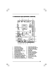
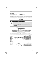
Blue) 25 Serial Port Connector (COM1) 12 Third SATAII Connector (SATAII_3; 1.3 Motherboard Layout (G41M-VGS3 / G41M-VS3) 1 23 4 5 17.0cm (6.7 in) PS2 Mouse PS2 Keyboard 1 PS2_USB_PWR1 ATX12V2 CPU_FAN1 1 COM1 FSB1333 ErP/EuP Ready Designed ... 2 S ATA I I _ 1 16 15 14 13 12 11 10 9 1 PS2_USB_PWR1 Jumper 15 USB 2.0 Header (USB4_5, Blue) 2 ATX 12V Connector (ATX12V2) 16 Chassis Fan Connector (CHA_FAN1) 3 CPU Fan Connector (CPU_FAN1) 17 USB 2.0 Header (USB6_7, Blue) 4 ATX Power Connector (ATXPWR1) 18 Clear CMOS Jumper (CLRCMOS1) 5 2 x 240-pin DDR3 DIMM Slots 19 BIOS SPI...
Blue) 25 Serial Port Connector (COM1) 12 Third SATAII Connector (SATAII_3; 1.3 Motherboard Layout (G41M-VGS3 / G41M-VS3) 1 23 4 5 17.0cm (6.7 in) PS2 Mouse PS2 Keyboard 1 PS2_USB_PWR1 ATX12V2 CPU_FAN1 1 COM1 FSB1333 ErP/EuP Ready Designed ... 2 S ATA I I _ 1 16 15 14 13 12 11 10 9 1 PS2_USB_PWR1 Jumper 15 USB 2.0 Header (USB4_5, Blue) 2 ATX 12V Connector (ATX12V2) 16 Chassis Fan Connector (CHA_FAN1) 3 CPU Fan Connector (CPU_FAN1) 17 USB 2.0 Header (USB6_7, Blue) 4 ATX Power Connector (ATXPWR1) 18 Clear CMOS Jumper (CLRCMOS1) 5 2 x 240-pin DDR3 DIMM Slots 19 BIOS SPI...

User Manual
Page 15
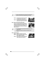
... lever by the edges where are marked with IHS (Integrated Heat Sink) up. black line black line Step 2-2. Orient the CPU with black lines. Otherwise, the CPU will be seriously damaged. Step 2. Pin1 orientation key notch orientation key notch Pin1 alignment key alignment key 775-LAND... CPU 775-Pin Socket 15 Rotate the load lever to fully open position at approximately 100 degrees. Insert the 775-LAND CPU: Step 2-1. Rotate the load plate to fully open position at approximately 135 ...
... lever by the edges where are marked with IHS (Integrated Heat Sink) up. black line black line Step 2-2. Orient the CPU with black lines. Otherwise, the CPU will be seriously damaged. Step 2. Pin1 orientation key notch orientation key notch Pin1 alignment key alignment key 775-LAND... CPU 775-Pin Socket 15 Rotate the load lever to fully open position at approximately 100 degrees. Insert the 775-LAND CPU: Step 2-1. Rotate the load plate to fully open position at approximately 135 ...
User Manual
Page 16
... load plate tab under retention tab of the socket. While pressing down lightly on center of PnP cap to assist in removal. 1. Verify that the CPU is recommended to use the cap tab to handle and avoid kicking off the PnP cap. 2. Step 2-3. This cap must be placed if returning the... service. Close the socket: Step 4-1. For proper inserting, please ensure to match the two orientation key notches of the CPU with the two alignment keys of load lever. 16 Carefully place the CPU into the socket by using a purely vertical motion. Step 4-3. Remove PnP Cap (Pick and Place Cap): Use your left...
... load plate tab under retention tab of the socket. While pressing down lightly on center of PnP cap to assist in removal. 1. Verify that the CPU is recommended to use the cap tab to handle and avoid kicking off the PnP cap. 2. Step 2-3. This cap must be placed if returning the... service. Close the socket: Step 4-1. For proper inserting, please ensure to match the two orientation key notches of the CPU with the two alignment keys of load lever. 16 Carefully place the CPU into the socket by using a purely vertical motion. Step 4-3. Remove PnP Cap (Pick and Place Cap): Use your left...
User Manual
Page 17
...on the motherboard (CPU_FAN1, see page 11, No. 3). Secure excess cable with tie-wrap to ensure cable does not interfere with the CPU fan connector on fastener caps with thumb to install and lock. Step 6. Step 2. Connect fan header with fan operation or contact other .... Step 4. Align fasteners with remaining fasteners. If you need to spray thermal interface material between the CPU and the heatsink to improve heat dissipation. Before you installed the heatsink, you press down on the motherboard. Place the heatsink onto the...
...on the motherboard (CPU_FAN1, see page 11, No. 3). Secure excess cable with tie-wrap to ensure cable does not interfere with the CPU fan connector on fastener caps with thumb to install and lock. Step 6. Step 2. Connect fan header with fan operation or contact other .... Step 4. Align fasteners with remaining fasteners. If you need to spray thermal interface material between the CPU and the heatsink to improve heat dissipation. Before you installed the heatsink, you press down on the motherboard. Place the heatsink onto the...
User Manual
Page 21
... are NOT jumpers. Primary IDE connector (Blue) (39-pin IDE1, see p.11 No. 27) FSB1 Default If you adopt FSB1333-CPU and DDR3 1333 memory module on this motherboard. Otherwise, the CPU and memory module may not work properly on the motherboard. 21 The current SATAII interface allows up to the SATA...
... are NOT jumpers. Primary IDE connector (Blue) (39-pin IDE1, see p.11 No. 27) FSB1 Default If you adopt FSB1333-CPU and DDR3 1333 memory module on this motherboard. Otherwise, the CPU and memory module may not work properly on the motherboard. 21 The current SATAII interface allows up to the SATA...
User Manual
Page 23
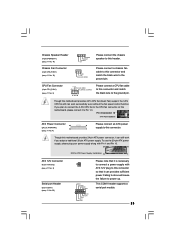
... you adopt a traditional 20-pin ATX power supply. Though this connector so that it can work if you plan to connect the 3-Pin CPU fan to the CPU fan connector on this motherboard, please connect it to power up. This COM1 header supports a serial port module. 23 Please connect a chassis.... 16) 1 SPEAKER DUMMY DUMMY +5V GND +12V CHA_FAN_SPEED Please connect the chassis speaker to this connector and match the black wire to the ground pin. CPU Fan Connector (4-pin CPU_FAN1) (see p.11 No. 25) RRXD1 DDTR#1 DDSR#1 CCTS#1 1 RRI#1 RRTS#1 GND TTXD1 DDCD#1 Please note that it is ...
... you adopt a traditional 20-pin ATX power supply. Though this connector so that it can work if you plan to connect the 3-Pin CPU fan to the CPU fan connector on this motherboard, please connect it to power up. This COM1 header supports a serial port module. 23 Please connect a chassis.... 16) 1 SPEAKER DUMMY DUMMY +5V GND +12V CHA_FAN_SPEED Please connect the chassis speaker to this connector and match the black wire to the ground pin. CPU Fan Connector (4-pin CPU_FAN1) (see p.11 No. 25) RRXD1 DDTR#1 DDSR#1 CCTS#1 1 RRI#1 RRTS#1 GND TTXD1 DDCD#1 Please note that it is ...
User Manual
Page 25
... set the selection from up to bottom side to the motherboard's SATAII connector. Before you to the warning on the support CD driver page. Therefore, CPU FSB is untied during overclocking, FSB enjoys better margin due to [Manual]. Please refer to install the SATA / SATAII hard disks. This section will guide...
... set the selection from up to bottom side to the motherboard's SATAII connector. Before you to the warning on the support CD driver page. Therefore, CPU FSB is untied during overclocking, FSB enjoys better margin due to [Manual]. Please refer to install the SATA / SATAII hard disks. This section will guide...
User Manual
Page 27
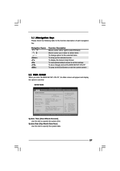
...exit the current screen 3.2 Main Screen When you enter the BIOS SETUP UTILITY, the Main screen will appear and display the system overview G41M-VGS3 BIOS SETUP UTILITY Main OC Tweaker Advanced H/W Monitor Boot Security Exit System Overview System Time System Date [14:00:09] [Fri... 12/18/2009] BIOS Version : G41M-VGS3 P1.00 Processor Type : Intel (R) Core (TM) 2 Duo CPU E6850 @ 3.00GHz (64bit) Processor Speed : 3148MHz Microcode Update : 6FB/B6 Cache Size : 1024KB Total Memory DDR3_1 DDR3_2 :...
...exit the current screen 3.2 Main Screen When you enter the BIOS SETUP UTILITY, the Main screen will appear and display the system overview G41M-VGS3 BIOS SETUP UTILITY Main OC Tweaker Advanced H/W Monitor Boot Security Exit System Overview System Time System Date [14:00:09] [Fri... 12/18/2009] BIOS Version : G41M-VGS3 P1.00 Processor Type : Intel (R) Core (TM) 2 Duo CPU E6850 @ 3.00GHz (64bit) Processor Speed : 3148MHz Microcode Update : 6FB/B6 Cache Size : 1024KB Total Memory DDR3_1 DDR3_2 :...
User Manual
Page 28
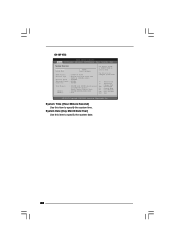
... Tweaker Advanced H/W Monitor Boot Security Exit System Overview System Time System Date [14:00:09] [Fri 12/18/2009] BIOS Version : G41M-VS3 P1.00 Processor Type : Intel (R) Core (TM) 2 Duo CPU E6850 @ 3.00GHz (64bit) Processor Speed : 3148MHz Microcode Update : 6FB/B6 Cache Size : 1024KB Total Memory DDR3_1 DDR3_2 : 1024MB with 128MB shared...
... Tweaker Advanced H/W Monitor Boot Security Exit System Overview System Time System Date [14:00:09] [Fri 12/18/2009] BIOS Version : G41M-VS3 P1.00 Processor Type : Intel (R) Core (TM) 2 Duo CPU E6850 @ 3.00GHz (64bit) Processor Speed : 3148MHz Microcode Update : 6FB/B6 Cache Size : 1024KB Total Memory DDR3_1 DDR3_2 : 1024MB with 128MB shared...
User Manual
Page 29
... to Sub Screen F1 General Help F9 Load Defaults F10 Save and Exit ESC Exit v02.54 (C) Copyright 1985-2005, American Megatrends, Inc. Overclock Mode CPU Frequency (MHz) PCIE Frequency (MHz) DRAM Voltage NB Voltage VTT Voltage GTLRef Voltage 1.60V 1.23V 1.20V 0.63Vtt [Auto] [Auto] [9] [Auto] [Auto] [133] [100] [Auto] [Auto... Exit OC Tweaker Settings DRAM Frequency DRAM Command Rate DRAM Timing Configuration Ratio CMOS Setting 9 Intel (R) SpeedStep (tm) tech. The configuration options depend on the CPU and memory module you adopt on this item to page 8 for the...
... to Sub Screen F1 General Help F9 Load Defaults F10 Save and Exit ESC Exit v02.54 (C) Copyright 1985-2005, American Megatrends, Inc. Overclock Mode CPU Frequency (MHz) PCIE Frequency (MHz) DRAM Voltage NB Voltage VTT Voltage GTLRef Voltage 1.60V 1.23V 1.20V 0.63Vtt [Auto] [Auto] [9] [Auto] [Auto] [133] [100] [Auto] [Auto... Exit OC Tweaker Settings DRAM Frequency DRAM Command Rate DRAM Timing Configuration Ratio CMOS Setting 9 Intel (R) SpeedStep (tm) tech. The configuration options depend on the CPU and memory module you adopt on this item to page 8 for the...

User Manual
Page 31
...Auto]. The default value of this feature is [Auto]. Ratio CMOS Setting If the ratio status is unlocked, you will be hidden if the current CPU does not support Intel (R) SpeedStep(tm) tech.. Intel (R) SpeedStep(tm) tech. Configuration options: [Auto], [Enabled] and [Disabled]. This item..., you plan to enable power savings. Overclock Mode Use this function. Configuration options: [Auto], [1.10V] to select Overclock Mode. If the CPU you adopt supports EIST (Intel (R) SpeedStep(tm) tech.), and you are allowed to load and save current setting user defaults? in advance. Processor...
...Auto]. The default value of this feature is [Auto]. Ratio CMOS Setting If the ratio status is unlocked, you will be hidden if the current CPU does not support Intel (R) SpeedStep(tm) tech.. Intel (R) SpeedStep(tm) tech. Configuration options: [Auto], [Enabled] and [Disabled]. This item..., you plan to enable power savings. Overclock Mode Use this function. Configuration options: [Auto], [1.10V] to select Overclock Mode. If the CPU you adopt supports EIST (Intel (R) SpeedStep(tm) tech.), and you are allowed to load and save current setting user defaults? in advance. Processor...
User Manual
Page 32
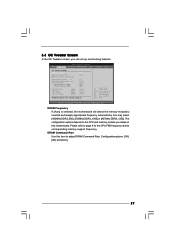
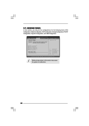
3.4 Advanced Screen In this section, you may set the configurations for CPU WARNING : Setting wrong values in this section may cause system to malfunction. Setting wrong values in below...Settings Options for the following items: CPU Configuration, Chipset Configuration, ACPI Configuration, Storage Configuration, PCIPnP Configuration, SuperIO Configuration, and USB Configuration. CPU Configuration Chipset Configuration ACPI Configuration Storage Configuration PCIPnP Configuration SuperIO Configuration USB Configuration BIOS Update Utility ASRock Instant Flash Select Screen Select Item ...
3.4 Advanced Screen In this section, you may set the configurations for CPU WARNING : Setting wrong values in this section may cause system to malfunction. Setting wrong values in below...Settings Options for the following items: CPU Configuration, Chipset Configuration, ACPI Configuration, Storage Configuration, PCIPnP Configuration, SuperIO Configuration, and USB Configuration. CPU Configuration Chipset Configuration ACPI Configuration Storage Configuration PCIPnP Configuration SuperIO Configuration USB Configuration BIOS Update Utility ASRock Instant Flash Select Screen Select Item ...

User Manual
Page 33
...to adjust the ratio value, please disable the option " Intel (R) SpeedStep(tm) tech." Overclock Mode Use this item appear to adjust CPU frequency. PCIE Frequency (MHz) Use this option is unlocked, you plan to [Enabled], a VMM (Virtual Machine Architecture) can utilize...adjust PCIE frequency. In the C1 power state, the processor maintains the context of Boot Failure Guard. 3.4.1 CPU Configuration BIOS SETUP UTILITY Advanced CPU Configuration Overclock Mode CPU Frequency (MHz) PCIE Frequency (MHz) Boot Failure Guard Spread Spectrum Ratio CMOS Setting 9 Enhanced Halt State ...
...to adjust the ratio value, please disable the option " Intel (R) SpeedStep(tm) tech." Overclock Mode Use this item appear to adjust CPU frequency. PCIE Frequency (MHz) Use this option is unlocked, you plan to [Enabled], a VMM (Virtual Machine Architecture) can utilize...adjust PCIE frequency. In the C1 power state, the processor maintains the context of Boot Failure Guard. 3.4.1 CPU Configuration BIOS SETUP UTILITY Advanced CPU Configuration Overclock Mode CPU Frequency (MHz) PCIE Frequency (MHz) Boot Failure Guard Spread Spectrum Ratio CMOS Setting 9 Enhanced Halt State ...
User Manual
Page 34
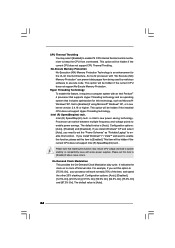
... the "Power Schemes" as Microsoft® Windows® XP. Processor can prevent data pages from overheated. This item will be hidden if the current CPU does not support Intel (R) SpeedStep(tm) tech.. Configuration options: [Auto], [Disabled], [12.5% On], [25.0% On], [37.5% On], [50....0% On], [62.5% On], [75.0% On] and [87.5% On]. This option will be hidden if the current CPU does not support CPU Thermal Throttling. Hyper Threading Technology To enable this item to execute code. Configuration options: [Auto], [Enabled] and [Disabled]. Intel (R) SpeedStep(tm)...
... the "Power Schemes" as Microsoft® Windows® XP. Processor can prevent data pages from overheated. This item will be hidden if the current CPU does not support Intel (R) SpeedStep(tm) tech.. Configuration options: [Auto], [Disabled], [12.5% On], [25.0% On], [37.5% On], [50....0% On], [62.5% On], [75.0% On] and [87.5% On]. This option will be hidden if the current CPU does not support CPU Thermal Throttling. Hyper Threading Technology To enable this item to execute code. Configuration options: [Auto], [Enabled] and [Disabled]. Intel (R) SpeedStep(tm)...


