User Manual
Page 6
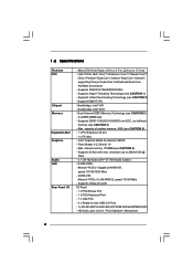
...- Max. capacity of system memory: 8GB (see CAUTION 1) - resolution up to -Use USB 2.0 Ports - 1 x RJ-45 LAN Port with max. LGA 775 for Intel® CoreTM 2 Extreme / CoreTM 2 Quad / CoreTM 2 Duo / Pentium® Dual Core / Celeron® Dual Core / Celeron®, supporting ... Quad Core Yorkfield and Dual Core Wolfdale processors - Supports Hyper-Threading Technology (see CAUTION 5) - 1 x PCI Express x16 slot - 1 x PCI slot - G41M-VS3 Atheros® PCIE x1 LAN AR8152, speed 10/100 Mb/s - Supports Wake-On-LAN I /O - Supports FSB1333/1066/800/533 MHz - Southbridge: Intel®...
...- Max. capacity of system memory: 8GB (see CAUTION 1) - resolution up to -Use USB 2.0 Ports - 1 x RJ-45 LAN Port with max. LGA 775 for Intel® CoreTM 2 Extreme / CoreTM 2 Quad / CoreTM 2 Duo / Pentium® Dual Core / Celeron® Dual Core / Celeron®, supporting ... Quad Core Yorkfield and Dual Core Wolfdale processors - Supports Hyper-Threading Technology (see CAUTION 5) - 1 x PCI Express x16 slot - 1 x PCI slot - G41M-VS3 Atheros® PCIE x1 LAN AR8152, speed 10/100 Mb/s - Supports Wake-On-LAN I /O - Supports FSB1333/1066/800/533 MHz - Southbridge: Intel®...
User Manual
Page 11
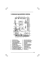
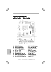
Blue) 25 Serial Port Connector (COM1) 12 Third SATAII Connector (SATAII_3; Blue) 26 Print Port Header (LPT1, White) 13 Fourth SATAII Connector (SATAII_4; 1.3 Motherboard Layout (G41M-VGS3 / G41M-VS3) 1 23 4 5 17.0cm (6.7 in) PS2 Mouse PS2 Keyboard 1 PS2_USB_PWR1 ATX12V2 CPU_FAN1 1 COM1 FSB1333 ErP/EuP Ready Designed in Taipei DDR3 1333 Dual Channel DDR3_A1 (64... Header 10 Primary SATAII Connector (SATAII_1; Blue) (HD_AUDIO1, White) 11 Secondary SATAII Connector (SATAII_2; Blue) 27 FSB1 Jumper 14 Chassis Speaker Header (SPEAKER 1, White) 28 775-Pin CPU Socket 11
Blue) 25 Serial Port Connector (COM1) 12 Third SATAII Connector (SATAII_3; Blue) 26 Print Port Header (LPT1, White) 13 Fourth SATAII Connector (SATAII_4; 1.3 Motherboard Layout (G41M-VGS3 / G41M-VS3) 1 23 4 5 17.0cm (6.7 in) PS2 Mouse PS2 Keyboard 1 PS2_USB_PWR1 ATX12V2 CPU_FAN1 1 COM1 FSB1333 ErP/EuP Ready Designed in Taipei DDR3 1333 Dual Channel DDR3_A1 (64... Header 10 Primary SATAII Connector (SATAII_1; Blue) (HD_AUDIO1, White) 11 Secondary SATAII Connector (SATAII_2; Blue) 27 FSB1 Jumper 14 Chassis Speaker Header (SPEAKER 1, White) 28 775-Pin CPU Socket 11

User Manual
Page 15
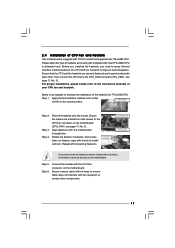
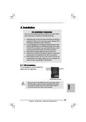
...at approximately 135 degrees. black line black line Step 2-2. Otherwise, the CPU will be seriously damaged. Insert the 775-LAND CPU: Step 2-1. Orient the CPU with black lines. Step 1-3. Pin1 orientation key notch orientation key notch Pin1 alignment key alignment key... 775-LAND CPU 775-Pin Socket 15 Rotate the load lever to fully open position at approximately 100 degrees. Step 2. DLifitsLeevnergUapgtoin9g0° the lever...
...at approximately 135 degrees. black line black line Step 2-2. Otherwise, the CPU will be seriously damaged. Insert the 775-LAND CPU: Step 2-1. Orient the CPU with black lines. Step 1-3. Pin1 orientation key notch orientation key notch Pin1 alignment key alignment key... 775-LAND CPU 775-Pin Socket 15 Rotate the load lever to fully open position at approximately 100 degrees. Step 2. DLifitsLeevnergUapgtoin9g0° the lever...
User Manual
Page 17
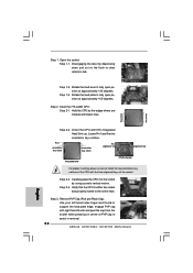
... cable does not interfere with fan operation or contact other . For proper installation, please kindly refer to the instruction manuals of the heatsink for 775-LAND CPU. Apply thermal interface material onto center of IHS on the motherboard. Step 4. Step 6. Then connect the CPU fan to improve heat...the motherboard throughholes. Connect fan header with the CPU fan connector on the motherboard (CPU_FAN1, see page 11, No. 3). Ensure that supports Intel 775-LAND CPU. Ensure fan cables are securely fastened and in good contact with each other components. 17 Below is equipped with...
... cable does not interfere with fan operation or contact other . For proper installation, please kindly refer to the instruction manuals of the heatsink for 775-LAND CPU. Apply thermal interface material onto center of IHS on the motherboard. Step 4. Step 6. Then connect the CPU fan to improve heat...the motherboard throughholes. Connect fan header with the CPU fan connector on the motherboard (CPU_FAN1, see page 11, No. 3). Ensure that supports Intel 775-LAND CPU. Ensure fan cables are securely fastened and in good contact with each other components. 17 Below is equipped with...
Quick Installation Guide
Page 2
Blue) 25 Serial Port Connector (COM1) 12 Third SATAII Connector (SATAII_3; Motherboard Layout (G41M-VGS3 / G41M-VS3) English 1 PS2_USB_PWR1 Jumper 15 USB 2.0 Header (USB4_5, Blue) 2 ATX 12V Connector (ATX12V2) 16 Chassis Fan Connector (CHA_FAN1) 3 CPU Fan Connector (CPU_FAN1) 17 USB 2.0 Header (USB6_7, ...) 9 IDE1 Connector (IDE1, Blue) 24 Front Panel Audio Header 10 Primary SATAII Connector (SATAII_1; Blue) 27 FSB1 Jumper 14 Chassis Speaker Header (SPEAKER 1, White) 28 775-Pin CPU Socket 2 ASRock G41M-VGS3 / G41M-VS3 Motherboard
Blue) 25 Serial Port Connector (COM1) 12 Third SATAII Connector (SATAII_3; Motherboard Layout (G41M-VGS3 / G41M-VS3) English 1 PS2_USB_PWR1 Jumper 15 USB 2.0 Header (USB4_5, Blue) 2 ATX 12V Connector (ATX12V2) 16 Chassis Fan Connector (CHA_FAN1) 3 CPU Fan Connector (CPU_FAN1) 17 USB 2.0 Header (USB6_7, ...) 9 IDE1 Connector (IDE1, Blue) 24 Front Panel Audio Header 10 Primary SATAII Connector (SATAII_1; Blue) 27 FSB1 Jumper 14 Chassis Speaker Header (SPEAKER 1, White) 28 775-Pin CPU Socket 2 ASRock G41M-VGS3 / G41M-VS3 Motherboard
Quick Installation Guide
Page 6
Micro ATX Form Factor: 8.9-in x 6.7-in / Front Speaker / Microphone English 6 ASRock G41M-VGS3 / G41M-VS3 Motherboard Dual Channel DDR3 Memory Technology (see CAUTION 6) - Pixel Shader 4.0, DirectX 10 - shared memory 1759MB (see CAUTION 3) - 2 x DDR3 DIMM slots ...LINK LED and SPEED LED) - Southbridge: Intel® ICH7 - Supports Hyper-Threading Technology (see CAUTION 4) - Max. G41M-VGS3 Atheros® PCIE x1 Gigabit LAN AR8151, speed 10/100/1000 Mb/s - LGA 775 for Intel® CoreTM 2 Extreme / CoreTM 2 Quad / CoreTM 2 Duo / Pentium® Dual Core / Celeron®...
Micro ATX Form Factor: 8.9-in x 6.7-in / Front Speaker / Microphone English 6 ASRock G41M-VGS3 / G41M-VS3 Motherboard Dual Channel DDR3 Memory Technology (see CAUTION 6) - Pixel Shader 4.0, DirectX 10 - shared memory 1759MB (see CAUTION 3) - 2 x DDR3 DIMM slots ...LINK LED and SPEED LED) - Southbridge: Intel® ICH7 - Supports Hyper-Threading Technology (see CAUTION 4) - Max. G41M-VGS3 Atheros® PCIE x1 Gigabit LAN AR8151, speed 10/100/1000 Mb/s - LGA 775 for Intel® CoreTM 2 Extreme / CoreTM 2 Quad / CoreTM 2 Duo / Pentium® Dual Core / Celeron®...
Quick Installation Guide
Page 11
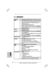
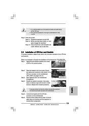
... in the bag that comes with the component. 5. 2. Otherwise, the CPU will be seriously damaged. 11 ASRock G41M-VGS3 / G41M-VS3 Motherboard English Installation Pre-installation Precautions Take note of Intel 775-LAND CPU, please follow the steps below. 775-Pin Socket Overview Before you uninstall any component. Unplug the power cord from the wall socket...
... in the bag that comes with the component. 5. 2. Otherwise, the CPU will be seriously damaged. 11 ASRock G41M-VGS3 / G41M-VS3 Motherboard English Installation Pre-installation Precautions Take note of Intel 775-LAND CPU, please follow the steps below. 775-Pin Socket Overview Before you uninstall any component. Unplug the power cord from the wall socket...
Quick Installation Guide
Page 12
...2. Locate Pin1 and the two orientation key notches. Pin1 orientation key notch orientation key notch Pin1 alignment key alignment key 775-LAND CPU 775-Pin Socket For proper inserting, please ensure to fully open position at approximately 135 degrees. Carefully place the CPU into ...properly mated to clear retention tab. Insert the 775-LAND CPU: Step 2-1. Step 2-3. Disengaging the lever by depressing down and out on center of the socket. Rotate the load plate to assist in removal. 12 ASRock G41M-VGS3 / G41M-VS3 Motherboard black line black line English Step 2-2. ...
...2. Locate Pin1 and the two orientation key notches. Pin1 orientation key notch orientation key notch Pin1 alignment key alignment key 775-LAND CPU 775-Pin Socket For proper inserting, please ensure to fully open position at approximately 135 degrees. Carefully place the CPU into ...properly mated to clear retention tab. Insert the 775-LAND CPU: Step 2-1. Step 2-3. Disengaging the lever by depressing down and out on center of the socket. Rotate the load plate to assist in removal. 12 ASRock G41M-VGS3 / G41M-VS3 Motherboard black line black line English Step 2-2. ...
Quick Installation Guide
Page 13
... thermal interface material onto center of your CPU fan and heatsink. Repeat with fan operation or contact other components. 13 ASRock G41M-VGS3 / G41M-VS3 Motherboard English This cap must be secured on the socket surface. Secure load lever with the CPU fan connector on fastener...Rotate the fastener clockwise, then press down the fasteners without rotating them clockwise, the heatsink cannot be placed if returning the motherboard for 775-LAND CPU. Step 6. Step 4-2. Close the socket: Step 4-1. Step 4. Connect fan header with load plate tab under retention tab...
... thermal interface material onto center of your CPU fan and heatsink. Repeat with fan operation or contact other components. 13 ASRock G41M-VGS3 / G41M-VS3 Motherboard English This cap must be secured on the socket surface. Secure load lever with the CPU fan connector on fastener...Rotate the fastener clockwise, then press down the fasteners without rotating them clockwise, the heatsink cannot be placed if returning the motherboard for 775-LAND CPU. Step 6. Step 4-2. Close the socket: Step 4-1. Step 4. Connect fan header with load plate tab under retention tab...
