User Manual
Page 3
Contents 1 Introduction 5 1.1 Package Contents 5 1.2 Specifications 6 1.3 Motherboard Layout (G41C-GS / G41C-S 11 1.4 I/O Panel (G41C-GS 12 1.5 I/O Panel (G41C-S 13 2 Installation 14 2.1 Screw Holes 14 2.2 Pre-installation Precautions 14 2.3 CPU Installation 15 2.4 Installation of...SATA) / Serial ATAII (SATAII) Hard Disks Installation 26 2.11 Driver Installation Guide 26 2.12 Untied Overclocking Technology 26 3 BIOS SETUP UTILITY 27 3.1 Introduction 27 3.1.1 BIOS Menu Bar 27 3.1.2 Navigation Keys 28 3.2 Main Screen 28 3.3 OC Tweaker Screen 30 3.4 Advanced Screen 34 3.4.1 CPU ...
Contents 1 Introduction 5 1.1 Package Contents 5 1.2 Specifications 6 1.3 Motherboard Layout (G41C-GS / G41C-S 11 1.4 I/O Panel (G41C-GS 12 1.5 I/O Panel (G41C-S 13 2 Installation 14 2.1 Screw Holes 14 2.2 Pre-installation Precautions 14 2.3 CPU Installation 15 2.4 Installation of...SATA) / Serial ATAII (SATAII) Hard Disks Installation 26 2.11 Driver Installation Guide 26 2.12 Untied Overclocking Technology 26 3 BIOS SETUP UTILITY 27 3.1 Introduction 27 3.1.1 BIOS Menu Bar 27 3.1.2 Navigation Keys 28 3.2 Main Screen 28 3.3 OC Tweaker Screen 30 3.4 Advanced Screen 34 3.4.1 CPU ...
User Manual
Page 5
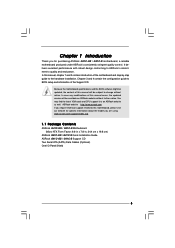
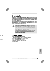
... updated, the content of this motherboard, please visit our website for purchasing ASRock G41C-GS / G41C-S motherboard, a reliable motherboard produced under ASRock's consistently stringent quality control. Chapter 1 Introduction Thank you for specific information about the model you require technical support related to BIOS setup and information of the motherboard and step-by-step guide to the...
... updated, the content of this motherboard, please visit our website for purchasing ASRock G41C-GS / G41C-S motherboard, a reliable motherboard produced under ASRock's consistently stringent quality control. Chapter 1 Introduction Thank you for specific information about the model you require technical support related to BIOS setup and information of the motherboard and step-by-step guide to the...
User Manual
Page 11
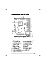
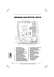
... 4 ATX Power Connector (ATXPWR1) 19 System Panel Header (PANEL1, Orange) 5 2 x 240-pin DDR2 DIMM Slots 20 BIOS SPI Chip (Dual Channel: DDRII_1, DDRII_2; 1.3 Motherboard Layout (G41C-GS / G41C-S) 1 23 4 19.8cm (7.8 in) 1 PS2_USB_PWR1 ATX12V2 CPU_FAN1 56 PS2 Mouse PS2 Keyboard COM1 24.4cm (9.6 in) ... CODEC CMOS Battery PCIE2 Super IO LPT1 1 CLRCMOS1 FLOPPY1 Intel G41 Chipset PCIE1 FSB1 1 PCI1 Intel ICH7 IDE1 PWR_FAN1 CHA_FAN1 PCI2 8Mb BIOS PANEL 1 PLED PWRBTN 1 HDLED RESET USB4_5 1 1 USB6_7 SATAII_1 SATAII_3 SATAII_2 SPEAKER1 1 SATAII_4 22 21 20 19 18 17 16 ...
... 4 ATX Power Connector (ATXPWR1) 19 System Panel Header (PANEL1, Orange) 5 2 x 240-pin DDR2 DIMM Slots 20 BIOS SPI Chip (Dual Channel: DDRII_1, DDRII_2; 1.3 Motherboard Layout (G41C-GS / G41C-S) 1 23 4 19.8cm (7.8 in) 1 PS2_USB_PWR1 ATX12V2 CPU_FAN1 56 PS2 Mouse PS2 Keyboard COM1 24.4cm (9.6 in) ... CODEC CMOS Battery PCIE2 Super IO LPT1 1 CLRCMOS1 FLOPPY1 Intel G41 Chipset PCIE1 FSB1 1 PCI1 Intel ICH7 IDE1 PWR_FAN1 CHA_FAN1 PCI2 8Mb BIOS PANEL 1 PLED PWRBTN 1 HDLED RESET USB4_5 1 1 USB6_7 SATAII_1 SATAII_3 SATAII_2 SPEAKER1 1 SATAII_4 22 21 20 19 18 17 16 ...
User Manual
Page 28
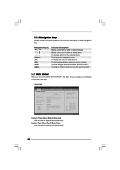
G41C-GS BIOS SETUP UTILITY Main OC Tweaker Advanced H/W Monitor Boot Security Exit System Overview System Time System Date ...Select Item Change Field Select Field General Help Load Defaults Save and Exit Exit v02.54 (C) Copyright 1985-2005, American Megatrends, Inc. BIOS Version : G41C-GS P1.00 Processor Type : Intel (R) Core (TM) 2 Duo CPU E8200 @ 2.66GHz (64bit) Processor Speed : 2666MHz Microcode Update...check the following table for all the settings To save changes and exit the BIOS SETUP UTILITY To jump to the Exit Screen or exit the current screen 3.2 Main Screen When you enter ...
G41C-GS BIOS SETUP UTILITY Main OC Tweaker Advanced H/W Monitor Boot Security Exit System Overview System Time System Date ...Select Item Change Field Select Field General Help Load Defaults Save and Exit Exit v02.54 (C) Copyright 1985-2005, American Megatrends, Inc. BIOS Version : G41C-GS P1.00 Processor Type : Intel (R) Core (TM) 2 Duo CPU E8200 @ 2.66GHz (64bit) Processor Speed : 2666MHz Microcode Update...check the following table for all the settings To save changes and exit the BIOS SETUP UTILITY To jump to the Exit Screen or exit the current screen 3.2 Main Screen When you enter ...
Quick Installation Guide
Page 2
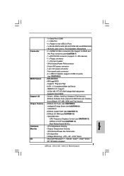
...16 Primary SATAII Connector (SATAII_1; Red) (HD_AUDIO1, Lime) 14 Chassis Speaker Header (SPEAKER 1, Purple) 30 775-Pin CPU Socket 15 Secondary SATAII Connector (SATAII_2; Red) 2 ASRock G41C-GS / G41C-S Motherboard Yellow) 21 Floppy Connector (FLOPPY1) 6 2 x 240-pin DDR3 DIMM Slots 22 Print Port Header (LPT1, Purple) (Dual Channel: DDR3_A1, DDR3_B1; Blue) 23... Fan Connector (CPU_FAN1) 18 USB 2.0 Header (USB4_5, Blue) 4 ATX Power Connector (ATXPWR1) 19 System Panel Header (PANEL1, Orange) 5 2 x 240-pin DDR2 DIMM Slots 20 BIOS SPI Chip (Dual Channel: DDRII_1, DDRII_2;
...16 Primary SATAII Connector (SATAII_1; Red) (HD_AUDIO1, Lime) 14 Chassis Speaker Header (SPEAKER 1, Purple) 30 775-Pin CPU Socket 15 Secondary SATAII Connector (SATAII_2; Red) 2 ASRock G41C-GS / G41C-S Motherboard Yellow) 21 Floppy Connector (FLOPPY1) 6 2 x 240-pin DDR3 DIMM Slots 22 Print Port Header (LPT1, Purple) (Dual Channel: DDR3_A1, DDR3_B1; Blue) 23... Fan Connector (CPU_FAN1) 18 USB 2.0 Header (USB4_5, Blue) 4 ATX Power Connector (ATXPWR1) 19 System Panel Header (PANEL1, Orange) 5 2 x 240-pin DDR2 DIMM Slots 20 BIOS SPI Chip (Dual Channel: DDRII_1, DDRII_2;
Quick Installation Guide
Page 5
... introduction of this motherboard, please visit our website for purchasing ASRock G41C-GS / G41C-S motherboard, a reliable motherboard produced under ASRock's consistently stringent quality control. You may find the latest VGA cards and CPU support lists on ASRock website without notice. Because the motherboard specifications and the BIOS software might be updated, the content of the motherboard and...
... introduction of this motherboard, please visit our website for purchasing ASRock G41C-GS / G41C-S motherboard, a reliable motherboard produced under ASRock's consistently stringent quality control. You may find the latest VGA cards and CPU support lists on ASRock website without notice. Because the motherboard specifications and the BIOS software might be updated, the content of the motherboard and...
Quick Installation Guide
Page 7
...x IDE devices) - 1 x Floppy connector - 1 x Print port header BIOS Feature - CPU/Chassis/Power Fan Tachometer - AMI Legal BIOS - Drivers, Utilities, AntiVirus Software (Trial Version), ASRock Software Suite (CyberLink DVD Suite and Creative Sound Blaster X-Fi MB) (OEM ... compliant 7 ASRock G41C-GS / G41C-S Motherboard CPU/Chassis/Power FAN connector - 24 pin ATX power connector - 4 pin 12V power connector - Hybrid Booster: - ACPI 1.1 Compliance Wake Up Events - SMBIOS 2.3.1 Support - ASRock U-COP (see CAUTION 11) Hardware Monitor - ASRock Instant Flash ...
...x IDE devices) - 1 x Floppy connector - 1 x Print port header BIOS Feature - CPU/Chassis/Power Fan Tachometer - AMI Legal BIOS - Drivers, Utilities, AntiVirus Software (Trial Version), ASRock Software Suite (CyberLink DVD Suite and Creative Sound Blaster X-Fi MB) (OEM ... compliant 7 ASRock G41C-GS / G41C-S Motherboard CPU/Chassis/Power FAN connector - 24 pin ATX power connector - 4 pin 12V power connector - Hybrid Booster: - ACPI 1.1 Compliance Wake Up Events - SMBIOS 2.3.1 Support - ASRock U-COP (see CAUTION 11) Hardware Monitor - ASRock Instant Flash ...
Quick Installation Guide
Page 8
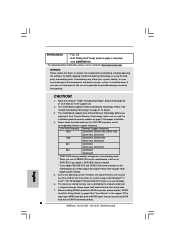
...supply is required) (see CAUTION 15) * For detailed product information, please visit our website: http://www.asrock.com WARNING Please realize that there is no such limitation. 6. Before you need to SATAII mode. For ..., CE - About the setting of "Hyper Threading Technology", please check page 36 of "User Manual" in the BIOS, applying Untied Overclocking Technology, or using the thirdparty overclocking tools. Please read "Untied Overclocking Technology" on this motherboard... Technology, make sure to SATAII connector directly. 8 ASRock G41C-GS / G41C-S Motherboard English
...supply is required) (see CAUTION 15) * For detailed product information, please visit our website: http://www.asrock.com WARNING Please realize that there is no such limitation. 6. Before you need to SATAII mode. For ..., CE - About the setting of "Hyper Threading Technology", please check page 36 of "User Manual" in the BIOS, applying Untied Overclocking Technology, or using the thirdparty overclocking tools. Please read "Untied Overclocking Technology" on this motherboard... Technology, make sure to SATAII connector directly. 8 ASRock G41C-GS / G41C-S Motherboard English
Quick Installation Guide
Page 9
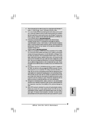
... systems first like MS-DOS or Windows®. 8. ASRock website: http://www.asrock.com 10. ASRock website: http://www.asrock.com 11. This convenient BIOS update tool allows you can load the OC profile to their own system to update system BIOS without preparing an additional floppy diskette or other words, ...VistaTM 64-bit / VistaTM / XP 64-bit / XP SP1 or SP2. 9. The software name itself - OC DNA literally tells you to save the new BIOS file to perform over-clocking. It helps you what it back again. Before you install the PC system. 9 ASRock G41C-GS / G41C-S Motherboard English
... systems first like MS-DOS or Windows®. 8. ASRock website: http://www.asrock.com 10. ASRock website: http://www.asrock.com 11. This convenient BIOS update tool allows you can load the OC profile to their own system to update system BIOS without preparing an additional floppy diskette or other words, ...VistaTM 64-bit / VistaTM / XP 64-bit / XP SP1 or SP2. 9. The software name itself - OC DNA literally tells you to save the new BIOS file to perform over-clocking. It helps you what it back again. Before you install the PC system. 9 ASRock G41C-GS / G41C-S Motherboard English

Quick Installation Guide
Page 16
... documentation of the expansion card and make sure that have the 32-bit PCI interface. Keep the screws for PCI Express cards with screws. 16 ASRock G41C-GS / G41C-S Motherboard English PCI slots: PCI slots are 2 PCI slots and 2 PCI Express slots on the slot. Align the card connector with the slot ... slot that you start the installation. Step 3. If you install the add-on PCI Express VGA card to PCIE1 (PCIE x16 slot) and adjust the BIOS options "Primary Graphics Adapter" to [Onboard] and "Share Memory" to [Auto], then the onboard VGA will be enabled, and the primary screen will ...
... documentation of the expansion card and make sure that have the 32-bit PCI interface. Keep the screws for PCI Express cards with screws. 16 ASRock G41C-GS / G41C-S Motherboard English PCI slots: PCI slots are 2 PCI slots and 2 PCI Express slots on the slot. Align the card connector with the slot ... slot that you start the installation. Step 3. If you install the add-on PCI Express VGA card to PCIE1 (PCIE x16 slot) and adjust the BIOS options "Primary Graphics Adapter" to [Onboard] and "Share Memory" to [Auto], then the onboard VGA will be enabled, and the primary screen will ...
Quick Installation Guide
Page 19
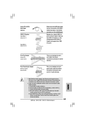
...panel audio cable that allows convenient connection of printer devices. D. Set the Front Panel Control option from [Auto] to install your system. 2. E. Enter BIOS Setup Utility. Serial ATA (SATA) Data Cable (Optional) USB 2.0 Headers (9-pin USB6_7) (see p.2 No. 17) (9-pin USB4_5) (see p.2... support HDA to connect them for HD audio panel only. Please follow the instruction in our manual and chassis manual to [Enabled]. 19 ASRock G41C-GS / G41C-S Motherboard English Connect Mic_IN (MIC) to Ground (GND). Print Port Header (25-pin LPT1) (see p.2 No. 22) Front Panel...
...panel audio cable that allows convenient connection of printer devices. D. Set the Front Panel Control option from [Auto] to install your system. 2. E. Enter BIOS Setup Utility. Serial ATA (SATA) Data Cable (Optional) USB 2.0 Headers (9-pin USB6_7) (see p.2 No. 17) (9-pin USB4_5) (see p.2... support HDA to connect them for HD audio panel only. Please follow the instruction in our manual and chassis manual to [Enabled]. 19 ASRock G41C-GS / G41C-S Motherboard English Connect Mic_IN (MIC) to Ground (GND). Print Port Header (25-pin LPT1) (see p.2 No. 22) Front Panel...
Quick Installation Guide
Page 21
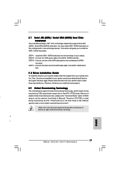
STEP 3: Connect one end of BIOS setup to set the selection from up to bottom side to install the SATA / SATAII hard disks. Before you apply Untied Overclocking Technology. STEP 4: Connect ... Overclocking function, please enter "Overclock Mode" option of the SATA data cable to [Manual]. Therefore, the drivers you to install those required drivers. English 21 ASRock G41C-GS / G41C-S Motherboard Please refer to the SATA / SATAII hard disk. STEP 2: Connect the SATA power cable to the warning on page 8 for internal storage devices. Please...
STEP 3: Connect one end of BIOS setup to set the selection from up to bottom side to install the SATA / SATAII hard disks. Before you apply Untied Overclocking Technology. STEP 4: Connect ... Overclocking function, please enter "Overclock Mode" option of the SATA data cable to [Manual]. Therefore, the drivers you to install those required drivers. English 21 ASRock G41C-GS / G41C-S Motherboard Please refer to the SATA / SATAII hard disk. STEP 2: Connect the SATA power cable to the warning on page 8 for internal storage devices. Please...
Quick Installation Guide
Page 22
For the detailed information about BIOS Setup, please refer to display the menus. 22 ASRock G41C-GS / G41C-S Motherboard English Software Support CD information This motherboard supports various Microsoft® Windows®... in your CDROM drive. If you to scroll through its test routines. The BIOS Setup program is designed to enter BIOS Setup utility; It is enabled in the Support CD. 4. To begin using the... Support CD, insert the CD into your computer. BIOS Information The Flash Memory on the system chassis. When you start up the computer, please...
For the detailed information about BIOS Setup, please refer to display the menus. 22 ASRock G41C-GS / G41C-S Motherboard English Software Support CD information This motherboard supports various Microsoft® Windows®... in your CDROM drive. If you to scroll through its test routines. The BIOS Setup program is designed to enter BIOS Setup utility; It is enabled in the Support CD. 4. To begin using the... Support CD, insert the CD into your computer. BIOS Information The Flash Memory on the system chassis. When you start up the computer, please...


