User Manual
Page 11
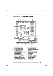
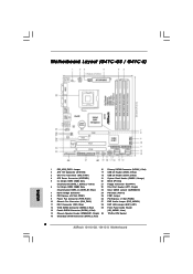
...Connector (SATAII_3; Yellow) 21 Floppy Connector (FLOPPY1) 6 2 x 240-pin DDR3 DIMM Slots 22 Print Port Header (LPT1, Purple) (Dual Channel: DDR3_A1, DDR3_B1; 1.3 Motherboard Layout (G41C-GS / G41C-S) 1 23 4 19.8cm (7.8 in) 1 PS2_USB_PWR1 ATX12V2 CPU_FAN1 56 PS2 Mouse PS2 Keyboard COM1 24.4cm (9.6 in) DDR3_B1 (64 bit, 240-FpinSBmo8d0ul0e) DDRII_2 (64 bit, 240... 8 9 10 11 12 13 1 PS2_USB_PWR1 Jumper 16 Primary SATAII Connector (SATAII_1; Red) (HD_AUDIO1, Lime) 14 Chassis Speaker Header (SPEAKER 1, Purple) 30 775-Pin CPU Socket 15 Secondary SATAII Connector (SATAII_2;
...Connector (SATAII_3; Yellow) 21 Floppy Connector (FLOPPY1) 6 2 x 240-pin DDR3 DIMM Slots 22 Print Port Header (LPT1, Purple) (Dual Channel: DDR3_A1, DDR3_B1; 1.3 Motherboard Layout (G41C-GS / G41C-S) 1 23 4 19.8cm (7.8 in) 1 PS2_USB_PWR1 ATX12V2 CPU_FAN1 56 PS2 Mouse PS2 Keyboard COM1 24.4cm (9.6 in) DDR3_B1 (64 bit, 240-FpinSBmo8d0ul0e) DDRII_2 (64 bit, 240... 8 9 10 11 12 13 1 PS2_USB_PWR1 Jumper 16 Primary SATAII Connector (SATAII_1; Red) (HD_AUDIO1, Lime) 14 Chassis Speaker Header (SPEAKER 1, Purple) 30 775-Pin CPU Socket 15 Secondary SATAII Connector (SATAII_2;
User Manual
Page 14
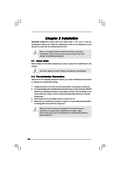
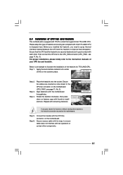
... bag that the power is switched off or the power cord is a Micro ATX form factor (9.6" x 7.8", 24.4 x 19.8 cm) motherboard. Chapter 2 Installation G41C-GS / G41C-S is detached from the wall socket before touching any component. 2. Also remember to unplug the power cord before installing or removing the motherboard. Before you uninstall any component, place...
... bag that the power is switched off or the power cord is a Micro ATX form factor (9.6" x 7.8", 24.4 x 19.8 cm) motherboard. Chapter 2 Installation G41C-GS / G41C-S is detached from the wall socket before touching any component. 2. Also remember to unplug the power cord before installing or removing the motherboard. Before you uninstall any component, place...
User Manual
Page 15
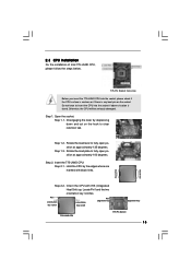
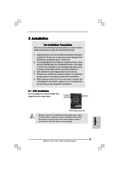
...2-2. 2.3 CPU Installation For the installation of Intel 775-LAND CPU, please follow the steps below. 775-Pin Socket Overview Before you insert the 775-LAND CPU into the socket if above situation is any bent pin on the ShoockoetkMatrokedcCleoranerr retention tab. Insert the 775-LAND CPU: Step 2-1.... Rotate the load lever to insert the CPU into the socket, please check if the CPU surface is unclean or if there is found. Do not force to fully open position at approximately 135 ...
...2-2. 2.3 CPU Installation For the installation of Intel 775-LAND CPU, please follow the steps below. 775-Pin Socket Overview Before you insert the 775-LAND CPU into the socket if above situation is any bent pin on the ShoockoetkMatrokedcCleoranerr retention tab. Insert the 775-LAND CPU: Step 2-1.... Rotate the load lever to insert the CPU into the socket, please check if the CPU surface is unclean or if there is found. Do not force to fully open position at approximately 135 ...
User Manual
Page 16
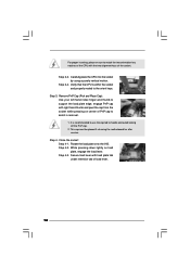
... plate onto the IHS. Step 4-2. Step 4-3. Secure load lever with right hand thumb and peel the cap from the socket while pressing on load plate, engage the load lever. Step 2-4. Step 3. Close the socket: Step 4-1. Step 4. For proper inserting, please ensure to handle and avoid kicking off the PnP cap. 2. Verify... CPU is recommended to use the cap tab to match the two orientation key notches of the CPU with the two alignment keys of the socket. While pressing down lightly on center of load lever. 16 Remove PnP Cap (Pick and Place Cap): Use your left hand index finger and...
... plate onto the IHS. Step 4-2. Step 4-3. Secure load lever with right hand thumb and peel the cap from the socket while pressing on load plate, engage the load lever. Step 2-4. Step 3. Close the socket: Step 4-1. Step 4. For proper inserting, please ensure to handle and avoid kicking off the PnP cap. 2. Verify... CPU is recommended to use the cap tab to match the two orientation key notches of the CPU with the two alignment keys of the socket. While pressing down lightly on center of load lever. 16 Remove PnP Cap (Pick and Place Cap): Use your left hand index finger and...
User Manual
Page 17
... heatsink to the CPU_FAN connector (CPU_FAN1, see page 11, No. 3). Step 6. Then connect the CPU fan to improve heat dissipation. Place the heatsink onto the socket. Ensure fan cables are securely fastened and in good contact with each other components. 17 Below is equipped with 775-Pin... socket that the CPU and the heatsink are oriented on the motherboard (CPU_FAN1, see page 11, No. 3). Step 2. Repeat with Intel 775-LAND CPU to the ...
... heatsink to the CPU_FAN connector (CPU_FAN1, see page 11, No. 3). Step 6. Then connect the CPU fan to improve heat dissipation. Place the heatsink onto the socket. Ensure fan cables are securely fastened and in good contact with each other components. 17 Below is equipped with 775-Pin... socket that the CPU and the heatsink are oriented on the motherboard (CPU_FAN1, see page 11, No. 3). Step 2. Repeat with Intel 775-LAND CPU to the ...
Quick Installation Guide
Page 2
... (SATAII_3; Red) (HD_AUDIO1, Lime) 14 Chassis Speaker Header (SPEAKER 1, Purple) 30 775-Pin CPU Socket 15 Secondary SATAII Connector (SATAII_2; Red) 29 Front Panel Audio Header 13 Fourth SATAII Connector (SATAII_4; Red) 2 ASRock G41C-GS / G41C-S Motherboard Red) 2 ATX 12V Connector (ATX12V2) 17 USB 2.0 Header (USB6_7, Blue) 3 CPU Fan... Floppy Connector (FLOPPY1) 6 2 x 240-pin DDR3 DIMM Slots 22 Print Port Header (LPT1, Purple) (Dual Channel: DDR3_A1, DDR3_B1; Motherboard Layout (G41C-GS / G41C-S) English 1 PS2_USB_PWR1 Jumper 16 Primary SATAII Connector (SATAII_1;
... (SATAII_3; Red) (HD_AUDIO1, Lime) 14 Chassis Speaker Header (SPEAKER 1, Purple) 30 775-Pin CPU Socket 15 Secondary SATAII Connector (SATAII_2; Red) 29 Front Panel Audio Header 13 Fourth SATAII Connector (SATAII_4; Red) 2 ASRock G41C-GS / G41C-S Motherboard Red) 2 ATX 12V Connector (ATX12V2) 17 USB 2.0 Header (USB6_7, Blue) 3 CPU Fan... Floppy Connector (FLOPPY1) 6 2 x 240-pin DDR3 DIMM Slots 22 Print Port Header (LPT1, Purple) (Dual Channel: DDR3_A1, DDR3_B1; Motherboard Layout (G41C-GS / G41C-S) English 1 PS2_USB_PWR1 Jumper 16 Primary SATAII Connector (SATAII_1;
Quick Installation Guide
Page 11
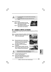
... handle components. 3. Otherwise, the CPU will be seriously damaged. 11 ASRock G41C-GS / G41C-S Motherboard English Doing so may cause severe damage to the motherboard, peripherals, and/or components. 2. Unplug the power cord from the wall socket before you insert the 775-LAND CPU into the screw holes to secure... the ICs. 4. Installation Pre-installation Precautions Take note of Intel 775-LAND CPU, please follow the steps below. 775-Pin Socket Overview Before you install motherboard components or change any bent pin on the carpet or the like. When placing screws into the...
... handle components. 3. Otherwise, the CPU will be seriously damaged. 11 ASRock G41C-GS / G41C-S Motherboard English Doing so may cause severe damage to the motherboard, peripherals, and/or components. 2. Unplug the power cord from the wall socket before you insert the 775-LAND CPU into the screw holes to secure... the ICs. 4. Installation Pre-installation Precautions Take note of Intel 775-LAND CPU, please follow the steps below. 775-Pin Socket Overview Before you install motherboard components or change any bent pin on the carpet or the like. When placing screws into the...
Quick Installation Guide
Page 12
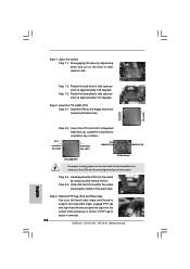
Step 1-2. Rotate the load lever to assist in removal. 12 ASRock G41C-GS / G41C-S Motherboard Step 2. Locate Pin1 and the two orientation key notches. Carefully place the CPU into the socket by depressing down and out on center of PnP cap to fully open position at approximately 135 degrees. ...3. Insert the 775-LAND CPU: Step 2-1. Pin1 orientation key notch orientation key notch Pin1 alignment key alignment key 775-LAND CPU 775-Pin Socket For proper inserting, please ensure to clear retention tab. Step 1. Step 1-3. Hold the CPU by the edges where are marked with IHS...
Step 1-2. Rotate the load lever to assist in removal. 12 ASRock G41C-GS / G41C-S Motherboard Step 2. Locate Pin1 and the two orientation key notches. Carefully place the CPU into the socket by depressing down and out on center of PnP cap to fully open position at approximately 135 degrees. ...3. Insert the 775-LAND CPU: Step 2-1. Pin1 orientation key notch orientation key notch Pin1 alignment key alignment key 775-LAND CPU 775-Pin Socket For proper inserting, please ensure to clear retention tab. Step 1. Step 1-3. Hold the CPU by the edges where are marked with IHS...
Quick Installation Guide
Page 13
.... Below is recommended to use the cap tab to the CPU fan connector on the socket surface. Step 3. Step 1. Ensure fan cables are oriented on the motherboard. Repeat with fan operation or contact other components. 13 ASRock G41C-GS / G41C-S Motherboard Secure excess cable with tie-wrap to illustrate the installation of your CPU fan...
.... Below is recommended to use the cap tab to the CPU fan connector on the socket surface. Step 3. Step 1. Ensure fan cables are oriented on the motherboard. Repeat with fan operation or contact other components. 13 ASRock G41C-GS / G41C-S Motherboard Secure excess cable with tie-wrap to illustrate the installation of your CPU fan...
