
User Manual
Page 6
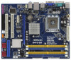
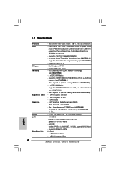
1.2 Specifications Platform CPU Chipset Memory Expansion Slot Graphics Audio LAN Rear Panel I /O Panel - 1 x PS/2 Mouse Port - 1 x PS/2 Keyboard Port 6 LGA 775 for Intel® CoreTM 2 Extreme / CoreTM 2 Quad / CoreTM 2 Duo / Pentium® Dual Core / Celeron® Dual Core / Celeron®, supporting Penryn.../ 8102EL, speed 10/100 Mb/s - Micro ATX Form Factor: 9.6-in x 7.8-in, 24.4 cm x 19.8 cm - Supports Wake-On-LAN I /O - G41C-GS: Realtek PCIE x1 Gigabit LAN RTL8111DL, speed 10/100/1000 Mb/s - Supports DDR3 1333(OC)/1066/800 non-ECC, un-buffered memory (see CAUTION 1) - Supports ...
1.2 Specifications Platform CPU Chipset Memory Expansion Slot Graphics Audio LAN Rear Panel I /O Panel - 1 x PS/2 Mouse Port - 1 x PS/2 Keyboard Port 6 LGA 775 for Intel® CoreTM 2 Extreme / CoreTM 2 Quad / CoreTM 2 Duo / Pentium® Dual Core / Celeron® Dual Core / Celeron®, supporting Penryn.../ 8102EL, speed 10/100 Mb/s - Micro ATX Form Factor: 9.6-in x 7.8-in, 24.4 cm x 19.8 cm - Supports Wake-On-LAN I /O - G41C-GS: Realtek PCIE x1 Gigabit LAN RTL8111DL, speed 10/100/1000 Mb/s - Supports DDR3 1333(OC)/1066/800 non-ECC, un-buffered memory (see CAUTION 1) - Supports ...
User Manual
Page 11
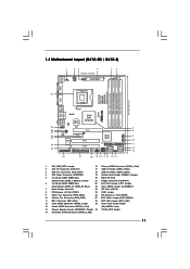
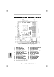
...29 Front Panel Audio Header 13 Fourth SATAII Connector (SATAII_4; Red) (HD_AUDIO1, Lime) 14 Chassis Speaker Header (SPEAKER 1, Purple) 30 775-Pin CPU Socket 15 Secondary SATAII Connector (SATAII_2; Blue) 23 Clear CMOS Jumper (CLRCMOS1) 7 North Bridge Controller 24 PCI Slots (PCI1...System Panel Header (PANEL1, Orange) 5 2 x 240-pin DDR2 DIMM Slots 20 BIOS SPI Chip (Dual Channel: DDRII_1, DDRII_2; 1.3 Motherboard Layout (G41C-GS / G41C-S) 1 23 4 19.8cm (7.8 in) 1 PS2_USB_PWR1 ATX12V2 CPU_FAN1 56 PS2 Mouse PS2 Keyboard COM1 24.4cm (9.6 in) DDR3_B1 (64 bit, 240-...
...29 Front Panel Audio Header 13 Fourth SATAII Connector (SATAII_4; Red) (HD_AUDIO1, Lime) 14 Chassis Speaker Header (SPEAKER 1, Purple) 30 775-Pin CPU Socket 15 Secondary SATAII Connector (SATAII_2; Blue) 23 Clear CMOS Jumper (CLRCMOS1) 7 North Bridge Controller 24 PCI Slots (PCI1...System Panel Header (PANEL1, Orange) 5 2 x 240-pin DDR2 DIMM Slots 20 BIOS SPI Chip (Dual Channel: DDRII_1, DDRII_2; 1.3 Motherboard Layout (G41C-GS / G41C-S) 1 23 4 19.8cm (7.8 in) 1 PS2_USB_PWR1 ATX12V2 CPU_FAN1 56 PS2 Mouse PS2 Keyboard COM1 24.4cm (9.6 in) DDR3_B1 (64 bit, 240-...
User Manual
Page 15
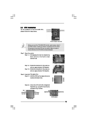
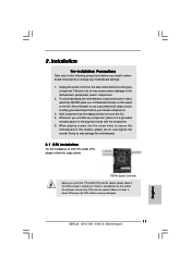
...degrees. Hold the CPU by depressing down and out on the socket. Pin1 orientation key notch orientation key notch Pin1 alignment key alignment key 775-LAND CPU 775-Pin Socket 15 Otherwise, the CPU will be seriously damaged. Step 1-3. Rotate the load lever to insert the CPU into the socket, ...please check if the CPU surface is unclean or if there is found. Insert the 775-LAND CPU: Step 2-1. Orient the CPU with black lines. Open the socket: CPU Marked Corner Step 1-1. Step 1-2. Step 2. 2.3 CPU Installation For the ...
...degrees. Hold the CPU by depressing down and out on the socket. Pin1 orientation key notch orientation key notch Pin1 alignment key alignment key 775-LAND CPU 775-Pin Socket 15 Otherwise, the CPU will be seriously damaged. Step 1-3. Rotate the load lever to insert the CPU into the socket, ...please check if the CPU surface is unclean or if there is found. Insert the 775-LAND CPU: Step 2-1. Orient the CPU with black lines. Open the socket: CPU Marked Corner Step 1-1. Step 1-2. Step 2. 2.3 CPU Installation For the ...
User Manual
Page 17
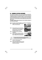
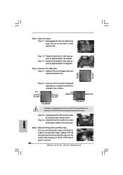
...installation, please kindly refer to the CPU fan connector on the socket surface. Repeat with the CPU fan connector on fastener caps with Intel 775-LAND CPU to dissipate heat. Step 5. Connect fan header with remaining fasteners. Below is equipped with each other components. 17 Step 3. ...Step 1. Step 2. 2.4 Installation of CPU Fan and Heatsink This motherboard is an example to illustrate the installation of the heatsink for 775-LAND CPU. Before you installed the heatsink, you press down on the motherboard. Ensure fan cables are securely fastened and in good contact ...
...installation, please kindly refer to the CPU fan connector on the socket surface. Repeat with the CPU fan connector on fastener caps with Intel 775-LAND CPU to dissipate heat. Step 5. Connect fan header with remaining fasteners. Below is equipped with each other components. 17 Step 3. ...Step 1. Step 2. 2.4 Installation of CPU Fan and Heatsink This motherboard is an example to illustrate the installation of the heatsink for 775-LAND CPU. Before you installed the heatsink, you press down on the motherboard. Ensure fan cables are securely fastened and in good contact ...
Quick Installation Guide
Page 2
... IDE1 Connector (IDE1, Blue) 28 EUP LAN Jumper (EUP_LAN1) 12 Third SATAII Connector (SATAII_3; Red) 2 ASRock G41C-GS / G41C-S Motherboard Red) (HD_AUDIO1, Lime) 14 Chassis Speaker Header (SPEAKER 1, Purple) 30 775-Pin CPU Socket 15 Secondary SATAII Connector (SATAII_2; Motherboard Layout (G41C-GS / G41C-S) English 1 PS2_USB_PWR1 Jumper 16 Primary SATAII Connector (SATAII_1; Yellow) 21 Floppy Connector (FLOPPY1) 6 2 x 240...
... IDE1 Connector (IDE1, Blue) 28 EUP LAN Jumper (EUP_LAN1) 12 Third SATAII Connector (SATAII_3; Red) 2 ASRock G41C-GS / G41C-S Motherboard Red) (HD_AUDIO1, Lime) 14 Chassis Speaker Header (SPEAKER 1, Purple) 30 775-Pin CPU Socket 15 Secondary SATAII Connector (SATAII_2; Motherboard Layout (G41C-GS / G41C-S) English 1 PS2_USB_PWR1 Jumper 16 Primary SATAII Connector (SATAII_1; Yellow) 21 Floppy Connector (FLOPPY1) 6 2 x 240...
Quick Installation Guide
Page 6
...non-ECC, un-buffered memory (see CAUTION 4) - Pixel Shader 4.0, DirectX 10 - Supports D-Sub with max. G41C-S: Realtek PCIE x1 LAN 8103EL / 8102EL, speed 10/100 Mb/s - LGA 775 for Intel® CoreTM 2 Extreme / CoreTM 2 Quad / CoreTM 2 Duo / Pentium® Dual Core /...Specifications Platform CPU Chipset Memory Expansion Slot Graphics Audio LAN Rear Panel I /O Panel - 1 x PS/2 Mouse Port - 1 x PS/2 Keyboard Port 6 ASRock G41C-GS / G41C-S Motherboard English Dual Channel DDR3/DDR2 Memory Technology (see CAUTION 2) - capacity of system memory: 8GB (see CAUTION 5) - 2 x DDR2 DIMM slots -...
...non-ECC, un-buffered memory (see CAUTION 4) - Pixel Shader 4.0, DirectX 10 - Supports D-Sub with max. G41C-S: Realtek PCIE x1 LAN 8103EL / 8102EL, speed 10/100 Mb/s - LGA 775 for Intel® CoreTM 2 Extreme / CoreTM 2 Quad / CoreTM 2 Duo / Pentium® Dual Core /...Specifications Platform CPU Chipset Memory Expansion Slot Graphics Audio LAN Rear Panel I /O Panel - 1 x PS/2 Mouse Port - 1 x PS/2 Keyboard Port 6 ASRock G41C-GS / G41C-S Motherboard English Dual Channel DDR3/DDR2 Memory Technology (see CAUTION 2) - capacity of system memory: 8GB (see CAUTION 5) - 2 x DDR2 DIMM slots -...
Quick Installation Guide
Page 11
Whenever you handle components. 3. Otherwise, the CPU will be seriously damaged. 11 ASRock G41C-GS / G41C-S Motherboard English To avoid damaging the motherboard components due to the chassis, please do not over-tighten the screws! When placing screws into the screw ... of the following precautions before touching any component, place it on the socket. Unplug the power cord from the wall socket before you insert the 775-LAND CPU into the socket if above situation is any motherboard settings. 1. Do not force to insert the CPU into the socket, please check if...
Whenever you handle components. 3. Otherwise, the CPU will be seriously damaged. 11 ASRock G41C-GS / G41C-S Motherboard English To avoid damaging the motherboard components due to the chassis, please do not over-tighten the screws! When placing screws into the screw ... of the following precautions before touching any component, place it on the socket. Unplug the power cord from the wall socket before you insert the 775-LAND CPU into the socket if above situation is any motherboard settings. 1. Do not force to insert the CPU into the socket, please check if...
Quick Installation Guide
Page 12
.... black line black line English Step 2-2. Pin1 orientation key notch orientation key notch Pin1 alignment key alignment key 775-LAND CPU 775-Pin Socket For proper inserting, please ensure to fully open position at approximately 135 degrees. Step 2-4. Insert the...775-LAND CPU: Step 2-1. Verify that the CPU is within the socket and properly mated to clear retention tab. Step 1-2. Hold the CPU by the edges where are marked with IHS (Integrated Heat Sink) up. Step 2-3. Open the socket: Step 1-1. Rotate the load plate to assist in removal. 12 ASRock G41C-GS / G41C...
.... black line black line English Step 2-2. Pin1 orientation key notch orientation key notch Pin1 alignment key alignment key 775-LAND CPU 775-Pin Socket For proper inserting, please ensure to fully open position at approximately 135 degrees. Step 2-4. Insert the...775-LAND CPU: Step 2-1. Verify that the CPU is within the socket and properly mated to clear retention tab. Step 1-2. Hold the CPU by the edges where are marked with IHS (Integrated Heat Sink) up. Step 2-3. Open the socket: Step 1-1. Rotate the load plate to assist in removal. 12 ASRock G41C-GS / G41C...
Quick Installation Guide
Page 13
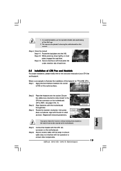
... the heatsink onto the socket. Step 5. Rotate the load plate onto the IHS. Step 4-2. Step 3. Align fasteners with fan operation or contact other components. 13 ASRock G41C-GS / G41C-S Motherboard It is an example to handle and avoid kicking off the PnP cap. 2. Step 1. Step 6. Below is recommended to use the cap tab to... the motherboard. Rotate the fastener clockwise, then press down the fasteners without rotating them clockwise, the heatsink cannot be placed if returning the motherboard for 775-LAND CPU.
... the heatsink onto the socket. Step 5. Rotate the load plate onto the IHS. Step 4-2. Step 3. Align fasteners with fan operation or contact other components. 13 ASRock G41C-GS / G41C-S Motherboard It is an example to handle and avoid kicking off the PnP cap. 2. Step 1. Step 6. Below is recommended to use the cap tab to... the motherboard. Rotate the fastener clockwise, then press down the fasteners without rotating them clockwise, the heatsink cannot be placed if returning the motherboard for 775-LAND CPU.
