
User Manual
Page 2
Products and corporate names appearing in this motherboard contains Perchlorate, a toxic substance controlled in Perchlorate Best Management Practices (BMP) regulations passed by the California Legislature. In no responsibility for any errors or ... of their respective companies, and are furnished for informational use only and subject to change without notice, and should not be constructed as a commitment by ASRock. When you discard the Lithium battery in California, USA, please follow the related regulations in advance. "Perchlorate Material-special handling may apply, see www....
Products and corporate names appearing in this motherboard contains Perchlorate, a toxic substance controlled in Perchlorate Best Management Practices (BMP) regulations passed by the California Legislature. In no responsibility for any errors or ... of their respective companies, and are furnished for informational use only and subject to change without notice, and should not be constructed as a commitment by ASRock. When you discard the Lithium battery in California, USA, please follow the related regulations in advance. "Perchlorate Material-special handling may apply, see www....

User Manual
Page 3
Contents 1 Introduction ...5 1.1 1.2 1.3 1.4 Package Contents ...Specifications ...Motherboard Layout ...I/O Panel ...5 6 10 11 2 Installation ...12 2.1 Screw Holes ...12 2.2 Pre-installation Precautions ...12 2.3 CPU Installation ...13 2.4 Installation of Heatsink and CPU fan ...15 2.5 Installation of ...
Contents 1 Introduction ...5 1.1 1.2 1.3 1.4 Package Contents ...Specifications ...Motherboard Layout ...I/O Panel ...5 6 10 11 2 Installation ...12 2.1 Screw Holes ...12 2.2 Pre-installation Precautions ...12 2.3 CPU Installation ...13 2.4 Installation of Heatsink and CPU fan ...15 2.5 Installation of ...

User Manual
Page 5
... endurance. In case any modifications of this motherboard, please visit our website for purchasing ASRock G31M-VS motherboard, a reliable motherboard produced under ASRock's consistently stringent quality control. www.asrock.com/support/index.asp 1.1 P ack age Contents Pack ackage ASRock G31M-VS Motherboard (Micro ATX Form Factor: 8.8-in x 6.7-in, 22.4 cm x 17.0 cm) ASRock G31M-VS Quick Installation Guide ASRock G31M-VS Support CD One 80-conductor Ultra ATA...
... endurance. In case any modifications of this motherboard, please visit our website for purchasing ASRock G31M-VS motherboard, a reliable motherboard produced under ASRock's consistently stringent quality control. www.asrock.com/support/index.asp 1.1 P ack age Contents Pack ackage ASRock G31M-VS Motherboard (Micro ATX Form Factor: 8.8-in x 6.7-in, 22.4 cm x 17.0 cm) ASRock G31M-VS Quick Installation Guide ASRock G31M-VS Support CD One 80-conductor Ultra ATA...

User Manual
Page 8
...for USB 2.0 works fine under Windows® XP and Windows® VistaTM. CAUTION! 1. 2. 3. This motherboard supports Untied Overclocking Technology. Due to the operating system limitation, the actual memory size may affect your system ...asrock.com 6. 8 Overclocking may be done at your hardware devices to change. In other words, it is defined by overclocking. Please read the "SATAII Hard Disk Setup Guide" on page 16 for details. Before you to SATAII connector, please read "Untied Overclocking Technology" on page 24 for proper installation. 4. This motherboard...
...for USB 2.0 works fine under Windows® XP and Windows® VistaTM. CAUTION! 1. 2. 3. This motherboard supports Untied Overclocking Technology. Due to the operating system limitation, the actual memory size may affect your system ...asrock.com 6. 8 Overclocking may be done at your hardware devices to change. In other words, it is defined by overclocking. Please read the "SATAII Hard Disk Setup Guide" on page 16 for details. Before you to SATAII connector, please read "Untied Overclocking Technology" on page 24 for proper installation. 4. This motherboard...

User Manual
Page 9
Before you install the PC system. 9 To improve heat dissipation, remember to perform over-clocking. Frequencies other than the recommended CPU bus frequencies may cause the instability of the system or damage the CPU. 11. While CPU overheat is not recommended to spray thermal grease between the CPU and the heatsink when you resume the system, please check if the CPU fan on the motherboard functions properly and unplug the power cord, then plug it is detected, the system will automatically shutdown. 10. Although this motherboard offers stepless control, it back again.
Before you install the PC system. 9 To improve heat dissipation, remember to perform over-clocking. Frequencies other than the recommended CPU bus frequencies may cause the instability of the system or damage the CPU. 11. While CPU overheat is not recommended to spray thermal grease between the CPU and the heatsink when you resume the system, please check if the CPU fan on the motherboard functions properly and unplug the power cord, then plug it is detected, the system will automatically shutdown. 10. Although this motherboard offers stepless control, it back again.

User Manual
Page 10
... Header (HD_AUDIO1, Lime) Print Port Header (LPT1, Purple) 10 Red) 12 13 14 15 16 17 18 19 20 21 22 Primary SATAII Connector (SATAII_1; 1.3 Motherboard Layout 1 2 3 17.0cm (6.7 in) PS2 Keyboard PS2 Mouse 4 5 1 PS2_USB_PWR1 ATX12V2 CPU_FAN1 FSB1333 DDR2 800 Dual Channel DDRII_1 (64 bit, 240-pin module) DDRII_2 ...: RJ-45 B: USB1 Super IO 22 Center: Line Out Bottom: Mic In Top: Line In LAN PHY LPT1 Intel G31 Chipset 21 20 19 HD_AUDIO1 G31M-VS USB 2.0 T: USB2 B: USB3 22.4cm (8.8 in) 1 COM1 VGA1 1 6 PCIE1 CD1 AUDIO CODEC 18 17 16 15 4Mb BIOS CMOS Battery RoHS PCI1 Intel ...
... Header (HD_AUDIO1, Lime) Print Port Header (LPT1, Purple) 10 Red) 12 13 14 15 16 17 18 19 20 21 22 Primary SATAII Connector (SATAII_1; 1.3 Motherboard Layout 1 2 3 17.0cm (6.7 in) PS2 Keyboard PS2 Mouse 4 5 1 PS2_USB_PWR1 ATX12V2 CPU_FAN1 FSB1333 DDR2 800 Dual Channel DDRII_1 (64 bit, 240-pin module) DDRII_2 ...: RJ-45 B: USB1 Super IO 22 Center: Line Out Bottom: Mic In Top: Line In LAN PHY LPT1 Intel G31 Chipset 21 20 19 HD_AUDIO1 G31M-VS USB 2.0 T: USB2 B: USB3 22.4cm (8.8 in) 1 COM1 VGA1 1 6 PCIE1 CD1 AUDIO CODEC 18 17 16 15 4Mb BIOS CMOS Battery RoHS PCI1 Intel ...

User Manual
Page 12
...damage to do not touch the ICs. 4. Hold components by circles to secure the motherboard to do so may damage the motherboard. 2.2 Pre-installation Precautions Take note of your motherboard directly on a grounded antistatic pad or in the bag that the power is switched...the motherboard, study the configuration of the following precautions before touching any component, ensure that comes with the component. Doing so may cause physical injuries to motherboard components. 2.1 Screw Holes Place screws into it on the carpet or the like. Chapter 2 Installation G31M-VS is...
...damage to do not touch the ICs. 4. Hold components by circles to secure the motherboard to do so may damage the motherboard. 2.2 Pre-installation Precautions Take note of your motherboard directly on a grounded antistatic pad or in the bag that the power is switched...the motherboard, study the configuration of the following precautions before touching any component, ensure that comes with the component. Doing so may cause physical injuries to motherboard components. 2.1 Screw Holes Place screws into it on the carpet or the like. Chapter 2 Installation G31M-VS is...

User Manual
Page 14
... thumb to the orient keys. While pressing down lightly on center of the socket. Step 2-3. Step 4. Step 4-3. This cap must be placed if returning the motherboard for after service. Step 3. Carefully place the CPU into the socket by using a purely vertical motion. Step 4-2. Step 2-4. It is within the socket and properly...
... thumb to the orient keys. While pressing down lightly on center of the socket. Step 2-3. Step 4. Step 4-3. This cap must be placed if returning the motherboard for after service. Step 3. Carefully place the CPU into the socket by using a purely vertical motion. Step 4-2. Step 2-4. It is within the socket and properly...

User Manual
Page 15
...Please adopt the type of the heatsink for 775-LAND CPU. Before you installed the heatsink, you press down on the motherboard. Step 4. Repeat with the motherboard throughholes. Below is equipped with 775-Pin socket that the CPU and the heatsink are oriented on side closest to ensure cable... does not interfere with the CPU fan connector on the motherboard (CPU_FAN1, see page 10, No. 3). Step 2. Rotate the fastener clockwise, then press down the fasteners without rotating them clockwise, the ...
...Please adopt the type of the heatsink for 775-LAND CPU. Before you installed the heatsink, you press down on the motherboard. Step 4. Repeat with the motherboard throughholes. Below is equipped with 775-Pin socket that the CPU and the heatsink are oriented on side closest to ensure cable... does not interfere with the CPU fan connector on the motherboard (CPU_FAN1, see page 10, No. 3). Step 2. Rotate the fastener clockwise, then press down the fasteners without rotating them clockwise, the ...

User Manual
Page 16
... slot by pressing the retaining clips outward. It will operate at incorrect orientation. It is properly seated. 16 otherwise, this motherboard and DIMM may be damaged. 2.5 Installation of Memor y Modules (DIMM) G31M-VS motherboard provides two 240-pin DDR2 (Double Data Rate 2) DIMM slots, and supports Dual Channel Memory Technology. Step 3. notch break notch...
... slot by pressing the retaining clips outward. It will operate at incorrect orientation. It is properly seated. 16 otherwise, this motherboard and DIMM may be damaged. 2.5 Installation of Memor y Modules (DIMM) G31M-VS motherboard provides two 240-pin DDR2 (Double Data Rate 2) DIMM slots, and supports Dual Channel Memory Technology. Step 3. notch break notch...

User Manual
Page 17
... onboard VGA will be enabled, and the primary screen will be onboard VGA. Step 3. PCIE slot: PCIE1 (PCIE x16 slot) is completely seated on this motherboard. Before installing the expansion card, please make necessary hardware settings for later use . Step 4. 17 2.6 Expansion Slots (PCI and PCI Express Slots) There are 1 PCI...
... onboard VGA will be enabled, and the primary screen will be onboard VGA. Step 3. PCIE slot: PCIE1 (PCIE x16 slot) is completely seated on this motherboard. Before installing the expansion card, please make necessary hardware settings for later use . Step 4. 17 2.6 Expansion Slots (PCI and PCI Express Slots) There are 1 PCI...

User Manual
Page 19
...SATAII hard disk or the SATAII connector on each drive. 2.8 Onboard Headers and Connectors Onboard headers and connectors are NOT jumpers. Either end of the motherboard! Do NOT place jumper caps over the headers and connectors will cause permanent damage of the SATA data cable can be connected to the power... see p.10, No. 12) (SATAII_2: see p.10 No. 8) PIN1 IDE1 connect the black end connect the blue end to the IDE devices to the motherboard 80-conductor ATA 66/100 cable Note: Please refer to the power connector of SATA power cable to 3.0 Gb/s data transfer rate. The current SATAII...
...SATAII hard disk or the SATAII connector on each drive. 2.8 Onboard Headers and Connectors Onboard headers and connectors are NOT jumpers. Either end of the motherboard! Do NOT place jumper caps over the headers and connectors will cause permanent damage of the SATA data cable can be connected to the power... see p.10, No. 12) (SATAII_2: see p.10 No. 8) PIN1 IDE1 connect the black end connect the blue end to the IDE devices to the motherboard 80-conductor ATA 66/100 cable Note: Please refer to the power connector of SATA power cable to 3.0 Gb/s data transfer rate. The current SATAII...

User Manual
Page 20
... P R E S EN C E# MI C _ R ET O U T_ R ET O U T2_L J_ S EN S E O U T2_ R MI C 2_ R MI C 2_L 1. C. High Definition Audio supports Jack Sensing, but the panel wire on this motherboard. Connect Audio_R (RIN) to OUT2_R and Audio_L (LIN) to install your system. 2. D. Please follow the instruction in our manual and chassis manual to OUT2_L. MIC_RET...
... P R E S EN C E# MI C _ R ET O U T_ R ET O U T2_L J_ S EN S E O U T2_ R MI C 2_ R MI C 2_L 1. C. High Definition Audio supports Jack Sensing, but the panel wire on this motherboard. Connect Audio_R (RIN) to OUT2_R and Audio_L (LIN) to install your system. 2. D. Please follow the instruction in our manual and chassis manual to OUT2_L. MIC_RET...

User Manual
Page 22
...connector, it can still work successfully even without the fan speed control function. Failing to do so will cause the failure to Pin 1-3. Though this motherboard provides 4-Pin CPU fan (Quiet Fan) support, the 3-Pin CPU fan still can work if you plan to connect the 3-Pin CPU fan ... 13 1 Please connect an ATX power supply to this connector so that it is necessary to connect a power supply with ATX 12V plug to this motherboard, please connect it can provides sufficient power. Pin 1-3 Connected 3-Pin Fan Installation ATX Power Connector (24-pin ATXPWR1) (see p.10 No. 2) Please note...
...connector, it can still work successfully even without the fan speed control function. Failing to do so will cause the failure to Pin 1-3. Though this motherboard provides 4-Pin CPU fan (Quiet Fan) support, the 3-Pin CPU fan still can work if you plan to connect the 3-Pin CPU fan ... 13 1 Please connect an ATX power supply to this connector so that it is necessary to connect a power supply with ATX 12V plug to this motherboard, please connect it can provides sufficient power. Pin 1-3 Connected 3-Pin Fan Installation ATX Power Connector (24-pin ATXPWR1) (see p.10 No. 2) Please note...

User Manual
Page 24
... enjoys better margin due to [CPU, PCIE, Async.]. Therefore, the drivers you apply Untied Overclocking Technology. 24 STEP 2: Connect the SATA power cable to the motherboard's SATAII connector. STEP 4: Connect the other end of the SATA data cable to the SATA / SATAII hard disk. 2 . 1 0 Serial A TA (SA TA)... / Serial A TAII (SA TAII) Hard Disks AT (SAT AT (SAT Installation This motherboard adopts Intel® ICH7 south bridge chipset that FSB can be auto-detected and listed on the support CD driver page. You may install SATA...
... enjoys better margin due to [CPU, PCIE, Async.]. Therefore, the drivers you apply Untied Overclocking Technology. 24 STEP 2: Connect the SATA power cable to the motherboard's SATAII connector. STEP 4: Connect the other end of the SATA data cable to the SATA / SATAII hard disk. 2 . 1 0 Serial A TA (SA TA)... / Serial A TAII (SA TAII) Hard Disks AT (SAT AT (SAT Installation This motherboard adopts Intel® ICH7 south bridge chipset that FSB can be auto-detected and listed on the support CD driver page. You may install SATA...

User Manual
Page 25
... press to enter the BIOS SETUP UTILITY after POST, restart the system by pressing + + , or by turning the system off and then back on the motherboard stores the BIOS SETUP UTILITY. Chapter 3: BIOS SETUP UTILITY 3.1 Introduction This section explains how to use the BIOS SETUP UTILITY to enter the BIOS SETUP...
... press to enter the BIOS SETUP UTILITY after POST, restart the system by pressing + + , or by turning the system off and then back on the motherboard stores the BIOS SETUP UTILITY. Chapter 3: BIOS SETUP UTILITY 3.1 Introduction This section explains how to use the BIOS SETUP UTILITY to enter the BIOS SETUP...
User Manual
Page 29
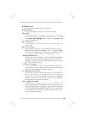
...such as Microsoft® Windows® XP. Boot Failure Guard Enable or disable the feature of this motherboard. Set to execute code. Ratio Status This is a read -only item, which displays whether the ratio status of this... find this item appear to allow you plan to the IA-32 Intel Architecture. This option will be [Auto] for this motherboard. Ratio CMOS Setting If the ratio status is "Locked" or "Unlocked". Spread Spectrum This item should always be hidden if...] if using Microsoft® Windows® XP, or Linux kernel version 2.4.18 or higher. When this motherboard.
...such as Microsoft® Windows® XP. Boot Failure Guard Enable or disable the feature of this motherboard. Set to execute code. Ratio Status This is a read -only item, which displays whether the ratio status of this... find this item appear to allow you plan to the IA-32 Intel Architecture. This option will be [Auto] for this motherboard. Ratio CMOS Setting If the ratio status is "Locked" or "Unlocked". Spread Spectrum This item should always be hidden if...] if using Microsoft® Windows® XP, or Linux kernel version 2.4.18 or higher. When this motherboard.

User Manual
Page 30
... issue with some power supplies. You may reduce CPU voltage and lead to enable or disable memory remap feature. The default value is selected, the motherboard will detect the memory module(s) inserted and assigns appropriate frequency automatically. Select Screen Select Item Change Option General Help Load Defaults Save and Exit Exit...
... issue with some power supplies. You may reduce CPU voltage and lead to enable or disable memory remap feature. The default value is selected, the motherboard will detect the memory module(s) inserted and assigns appropriate frequency automatically. Select Screen Select Item Change Option General Help Load Defaults Save and Exit Exit...

User Manual
Page 31
... card; Configuration options: [Fixed Mode] and [DVMT Mode]. DVMT (Dynamic Video Memory Technology) is issued. Onboard HD Audio Select [Auto], [Enabled] or [Disabled] for the motherboard through efficient memory utilization. DRAM tRCD This controls the latency between the DRAM active command and the read / write command.
... card; Configuration options: [Fixed Mode] and [DVMT Mode]. DVMT (Dynamic Video Memory Technology) is issued. Onboard HD Audio Select [Auto], [Enabled] or [Disabled] for the motherboard through efficient memory utilization. DRAM tRCD This controls the latency between the DRAM active command and the read / write command.

User Manual
Page 33
... AC/Power resumes and the system starts to boot up when the power recovers. Suspend to RAM This field allows you plan to use this motherboard to enable or disable ACPI HPET Table. Select [Auto] will enable this item to submit Windows® VistaTM certification. 33 RTC Alarm Power On Use...
... AC/Power resumes and the system starts to boot up when the power recovers. Suspend to RAM This field allows you plan to use this motherboard to enable or disable ACPI HPET Table. Select [Auto] will enable this item to submit Windows® VistaTM certification. 33 RTC Alarm Power On Use...


