
User Manual
Page 2
...: http://www.asrock.com 2 Operation is subject to change without written consent of the FCC Rules. "Perchlorate Material-special handling may not be registered trademarks or copyrights of their respective companies, and are furnished for a particular purpose. CALIFORNIA, USA ONLY The Lithium battery adopted on this motherboard contains Perchlorate, a toxic substance controlled...
...: http://www.asrock.com 2 Operation is subject to change without written consent of the FCC Rules. "Perchlorate Material-special handling may not be registered trademarks or copyrights of their respective companies, and are furnished for a particular purpose. CALIFORNIA, USA ONLY The Lithium battery adopted on this motherboard contains Perchlorate, a toxic substance controlled...

User Manual
Page 3
Contents 1 Introduction ...5 1.1 1.2 1.3 1.4 Package Contents ...Specifications ...Motherboard Layout ...I/O Panel ...5 6 10 11 2 Installation ...12 2.1 Screw Holes ...12 2.2 Pre-installation Precautions ...12 2.3 CPU Installation ...13 2.4 Installation of Heatsink and CPU fan ...15 2.5 Installation of ...
Contents 1 Introduction ...5 1.1 1.2 1.3 1.4 Package Contents ...Specifications ...Motherboard Layout ...I/O Panel ...5 6 10 11 2 Installation ...12 2.1 Screw Holes ...12 2.2 Pre-installation Precautions ...12 2.3 CPU Installation ...13 2.4 Installation of Heatsink and CPU fan ...15 2.5 Installation of ...

User Manual
Page 5
... manual, chapter 1 and 2 contain introduction of this motherboard, please visit our website for purchasing ASRock G31M-VS motherboard, a reliable motherboard produced under ASRock's consistently stringent quality control. www.asrock.com/support/index.asp 1.1 P ack age Contents Pack ackage ASRock G31M-VS Motherboard (Micro ATX Form Factor: 8.8-in x 6.7-in, 22.4 cm x 17.0 cm) ASRock G31M-VS Quick Installation Guide ASRock G31M-VS Support CD One 80-conductor Ultra ATA...
... manual, chapter 1 and 2 contain introduction of this motherboard, please visit our website for purchasing ASRock G31M-VS motherboard, a reliable motherboard produced under ASRock's consistently stringent quality control. www.asrock.com/support/index.asp 1.1 P ack age Contents Pack ackage ASRock G31M-VS Motherboard (Micro ATX Form Factor: 8.8-in x 6.7-in, 22.4 cm x 17.0 cm) ASRock G31M-VS Quick Installation Guide ASRock G31M-VS Support CD One 80-conductor Ultra ATA...

User Manual
Page 8
... without sacrificing computing performance. Please visit our website for the latest information. ASRock website: http://www.asrock.com 9. This motherboard supports Dual Channel Memory Technology. ASRock website: http://www.asrock.com 6. 8 Before you to surveil your system. For Windows® ... the setting of Intelligent Energy Saver. Before installing SATAII hard disk to SATAII connector, please read the installation guide of ASRock OC Tuner. CAUTION! 1. 2. 3. WARNING Please realize that delivers unparalleled power savings. Please check Intel ® website...
... without sacrificing computing performance. Please visit our website for the latest information. ASRock website: http://www.asrock.com 9. This motherboard supports Dual Channel Memory Technology. ASRock website: http://www.asrock.com 6. 8 Before you to surveil your system. For Windows® ... the setting of Intelligent Energy Saver. Before installing SATAII hard disk to SATAII connector, please read the installation guide of ASRock OC Tuner. CAUTION! 1. 2. 3. WARNING Please realize that delivers unparalleled power savings. Please check Intel ® website...

User Manual
Page 9
Before you install the PC system. 9 To improve heat dissipation, remember to perform over-clocking. While CPU overheat is not recommended to spray thermal grease between the CPU and the heatsink when you resume the system, please check if the CPU fan on the motherboard functions properly and unplug the power cord, then plug it is detected, the system will automatically shutdown. Frequencies other than the recommended CPU bus frequencies may cause the instability of the system or damage the CPU. 11. 10. Although this motherboard offers stepless control, it back again.
Before you install the PC system. 9 To improve heat dissipation, remember to perform over-clocking. While CPU overheat is not recommended to spray thermal grease between the CPU and the heatsink when you resume the system, please check if the CPU fan on the motherboard functions properly and unplug the power cord, then plug it is detected, the system will automatically shutdown. Frequencies other than the recommended CPU bus frequencies may cause the instability of the system or damage the CPU. 11. 10. Although this motherboard offers stepless control, it back again.

User Manual
Page 10
...Bridge Controller South Bridge Controller IDE1 Connector (IDE1, Blue) System Panel Header (PANEL1, Orange) Chassis Speaker Header (SPEAKER 1, Purple) Secondary SATAII Connector (SATAII_2; 1.3 Motherboard Layout 1 2 3 17.0cm (6.7 in) PS2 Keyboard PS2 Mouse 4 5 1 PS2_USB_PWR1 ATX12V2 CPU_FAN1 FSB1333 DDR2 800 Dual Channel DDRII_1 (64 bit, 240-pin... B: USB1 Super IO 22 Center: Line Out Bottom: Mic In Top: Line In LAN PHY LPT1 Intel G31 Chipset 21 20 19 HD_AUDIO1 G31M-VS USB 2.0 T: USB2 B: USB3 22.4cm (8.8 in) 1 COM1 VGA1 1 6 PCIE1 CD1 AUDIO CODEC 18 17 16 15 4Mb BIOS CMOS...
...Bridge Controller South Bridge Controller IDE1 Connector (IDE1, Blue) System Panel Header (PANEL1, Orange) Chassis Speaker Header (SPEAKER 1, Purple) Secondary SATAII Connector (SATAII_2; 1.3 Motherboard Layout 1 2 3 17.0cm (6.7 in) PS2 Keyboard PS2 Mouse 4 5 1 PS2_USB_PWR1 ATX12V2 CPU_FAN1 FSB1333 DDR2 800 Dual Channel DDRII_1 (64 bit, 240-pin... B: USB1 Super IO 22 Center: Line Out Bottom: Mic In Top: Line In LAN PHY LPT1 Intel G31 Chipset 21 20 19 HD_AUDIO1 G31M-VS USB 2.0 T: USB2 B: USB3 22.4cm (8.8 in) 1 COM1 VGA1 1 6 PCIE1 CD1 AUDIO CODEC 18 17 16 15 4Mb BIOS CMOS...

User Manual
Page 12
... and damages to ensure that the motherboard fits into the holes indicated by the edges and do so may cause severe damage to you uninstall any component, ensure that comes with the component. Chapter 2 Installation G31M-VS is detached from the wall socket ...before you install the motherboard, study the configuration of the following precautions before installing or removing the motherboard. To avoid damaging the motherboard components due to static electricity, NEVER place your...
... and damages to ensure that the motherboard fits into the holes indicated by the edges and do so may cause severe damage to you uninstall any component, ensure that comes with the component. Chapter 2 Installation G31M-VS is detached from the wall socket ...before you install the motherboard, study the configuration of the following precautions before installing or removing the motherboard. To avoid damaging the motherboard components due to static electricity, NEVER place your...

User Manual
Page 14
... two orientation key notches of the CPU with load plate tab under retention tab of the socket. This cap must be placed if returning the motherboard for after service. For proper inserting, please ensure to assist in removal. 1. Carefully place the CPU into the socket by using a purely vertical motion...
... two orientation key notches of the CPU with load plate tab under retention tab of the socket. This cap must be placed if returning the motherboard for after service. For proper inserting, please ensure to assist in removal. 1. Carefully place the CPU into the socket by using a purely vertical motion...

User Manual
Page 15
...3. Step 4. Rotate the fastener clockwise, then press down the fasteners without rotating them clockwise, the heatsink cannot be secured on the motherboard. Please adopt the type of heatsink and cooling fan compliant with thumb to dissipate heat. Align fasteners with each other components. 15 ...not interfere with remaining fasteners. Ensure that supports Intel 775-LAND CPU. Then connect the CPU fan to the CPU fan connector on the motherboard (CPU_FAN1, see page 10, No. 3). Step 1. Step 5. Apply thermal interface material onto center of IHS on side closest to the...
...3. Step 4. Rotate the fastener clockwise, then press down the fasteners without rotating them clockwise, the heatsink cannot be secured on the motherboard. Please adopt the type of heatsink and cooling fan compliant with thumb to dissipate heat. Align fasteners with each other components. 15 ...not interfere with remaining fasteners. Ensure that supports Intel 775-LAND CPU. Then connect the CPU fan to the CPU fan connector on the motherboard (CPU_FAN1, see page 10, No. 3). Step 1. Step 5. Apply thermal interface material onto center of IHS on side closest to the...

User Manual
Page 16
2.5 Installation of Memor y Modules (DIMM) G31M-VS motherboard provides two 240-pin DDR2 (Double Data Rate 2) DIMM slots, and supports Dual Channel Memory Technology. It is not ...module into the slot until the retaining clips at both ends fully snap back in place and the DIMM is unable to the motherboard and the DIMM if you force the DIMM into the slot at single channel mode. 1. 2. notch break notch break The DIMM... insert the DIMM into DDR2 slot; For dual channel configuration, you install only one correct orientation. otherwise, this motherboard and DIMM may be damaged. Step 3.
2.5 Installation of Memor y Modules (DIMM) G31M-VS motherboard provides two 240-pin DDR2 (Double Data Rate 2) DIMM slots, and supports Dual Channel Memory Technology. It is not ...module into the slot until the retaining clips at both ends fully snap back in place and the DIMM is unable to the motherboard and the DIMM if you force the DIMM into the slot at single channel mode. 1. 2. notch break notch break The DIMM... insert the DIMM into DDR2 slot; For dual channel configuration, you install only one correct orientation. otherwise, this motherboard and DIMM may be damaged. Step 3.

User Manual
Page 17
... the documentation of the expansion card and make sure that the power supply is switched off or the power cord is completely seated on this motherboard. PCIE slot: PCIE1 (PCIE x16 slot) is used for PCI Express card with screws. Before installing the expansion card, please make necessary hardware settings for...
... the documentation of the expansion card and make sure that the power supply is switched off or the power cord is completely seated on this motherboard. PCIE slot: PCIE1 (PCIE x16 slot) is used for PCI Express card with screws. Before installing the expansion card, please make necessary hardware settings for...

User Manual
Page 19
...end of the power supply. Please connect the black end of the SATA data cable can be connected to the power connector on the motherboard. Do NOT place jumper caps over the headers and connectors will cause permanent damage of your IDE device vendor for internal storage devices. Primary... p.10, No. 12) (SATAII_2: see p.10 No. 8) PIN1 IDE1 connect the black end connect the blue end to the IDE devices to the motherboard 80-conductor ATA 66/100 cable Note: Please refer to the power supply 19 2.8 Onboard Headers and Connectors Onboard headers and connectors are NOT jumpers...
...end of the power supply. Please connect the black end of the SATA data cable can be connected to the power connector on the motherboard. Do NOT place jumper caps over the headers and connectors will cause permanent damage of your IDE device vendor for internal storage devices. Primary... p.10, No. 12) (SATAII_2: see p.10 No. 8) PIN1 IDE1 connect the black end connect the blue end to the IDE devices to the motherboard 80-conductor ATA 66/100 cable Note: Please refer to the power supply 19 2.8 Onboard Headers and Connectors Onboard headers and connectors are NOT jumpers...

User Manual
Page 20
... panel wire on the chassis must support HDA to Ground (GND). B. You don't need to OUT2_L. MIC_RET and OUT_RET are two USB 2.0 headers on this motherboard. Connect Audio_R (RIN) to OUT2_R and Audio_L (LIN) to connect them for AC'97 audio panel. 20 Each USB 2.0 header can support two USB 2.0 ports...
... panel wire on the chassis must support HDA to Ground (GND). B. You don't need to OUT2_L. MIC_RET and OUT_RET are two USB 2.0 headers on this motherboard. Connect Audio_R (RIN) to OUT2_R and Audio_L (LIN) to connect them for AC'97 audio panel. 20 Each USB 2.0 header can support two USB 2.0 ports...

User Manual
Page 22
... No. 2) Please note that it can work if you plan to connect the 3-Pin CPU fan to the CPU fan connector on this motherboard, please connect it to this motherboard provides 4-Pin CPU fan (Quiet Fan) support, the 3-Pin CPU fan still can provides sufficient power. Though this connector so that it... 12 13 1 Please connect an ATX power supply to power up. 22 Failing to do so will cause the failure to this connector. Though this motherboard provides 24-pin ATX power connector, it can still work successfully even without the fan speed control function. To use the 20-pin ATX power...
... No. 2) Please note that it can work if you plan to connect the 3-Pin CPU fan to the CPU fan connector on this motherboard, please connect it to this motherboard provides 4-Pin CPU fan (Quiet Fan) support, the 3-Pin CPU fan still can provides sufficient power. Though this connector so that it... 12 13 1 Please connect an ATX power supply to power up. 22 Failing to do so will cause the failure to this connector. Though this motherboard provides 24-pin ATX power connector, it can still work successfully even without the fan speed control function. To use the 20-pin ATX power...

User Manual
Page 24
... on the support CD driver page. This section will guide you install can work properly. 2 . 1 2 Untied Overclocking T echnology Technology This motherboard supports Untied Overclocking Technology, which means during overclocking, but PCI / PCIE buses are in the fixed mode so that supports Serial ATA (SATA).... 24 2 . 1 0 Serial A TA (SA TA) / Serial A TAII (SA TAII) Hard Disks AT (SAT AT (SAT Installation This motherboard adopts Intel® ICH7 south bridge chipset that FSB can operate under a more stable overclocking environment. You may install SATA / SATAII hard disks on page...
... on the support CD driver page. This section will guide you install can work properly. 2 . 1 2 Untied Overclocking T echnology Technology This motherboard supports Untied Overclocking Technology, which means during overclocking, but PCI / PCIE buses are in the fixed mode so that supports Serial ATA (SATA).... 24 2 . 1 0 Serial A TA (SA TA) / Serial A TAII (SA TAII) Hard Disks AT (SAT AT (SAT Installation This motherboard adopts Intel® ICH7 south bridge chipset that FSB can operate under a more stable overclocking environment. You may install SATA / SATAII hard disks on page...

User Manual
Page 25
... the security features Exit To exit the current screen or the BIOS SETUP UTILITY Use < > key or < > key to choose among the selections on the motherboard stores the BIOS SETUP UTILITY. Chapter 3: BIOS SETUP UTILITY 3.1 Introduction This section explains how to use the BIOS SETUP UTILITY to configure your requirements Advanced...
... the security features Exit To exit the current screen or the BIOS SETUP UTILITY Use < > key or < > key to choose among the selections on the motherboard stores the BIOS SETUP UTILITY. Chapter 3: BIOS SETUP UTILITY 3.1 Introduction This section explains how to use the BIOS SETUP UTILITY to configure your requirements Advanced...
User Manual
Page 29
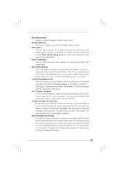
...) can prevent data pages from overheated. Ratio CMOS Setting If the ratio status is unlocked, you changing the ratio value of this motherboard. Hyper Threading Technology To enable this option is set to allow you plan to keep the CPU from being used by Vanderpool Technology....such as Microsoft® Windows® XP. Ratio Actual Value This is a read -only item, which displays whether the ratio status of this motherboard. CPU Thermal Throttling You may select [Enabled] to enable P4 CPU internal thermal control mechanism to adjust the ratio value, please disable the option...
...) can prevent data pages from overheated. Ratio CMOS Setting If the ratio status is unlocked, you changing the ratio value of this motherboard. Hyper Threading Technology To enable this option is set to allow you plan to keep the CPU from being used by Vanderpool Technology....such as Microsoft® Windows® XP. Ratio Actual Value This is a read -only item, which displays whether the ratio status of this motherboard. CPU Thermal Throttling You may select [Enabled] to enable P4 CPU internal thermal control mechanism to adjust the ratio value, please disable the option...

User Manual
Page 30
... compatibility when it is [Disabled]. You may reduce CPU voltage and lead to [Enabled]. Configuration options are [6], [5], [4], [3] and [Auto]. The default value is selected, the motherboard will be hidden if the current CPU does not support Intel (R) SpeedStep(tm) tech.. Please set to system stability or compatibility issue with some power...
... compatibility when it is [Disabled]. You may reduce CPU voltage and lead to [Enabled]. Configuration options are [6], [5], [4], [3] and [Auto]. The default value is selected, the motherboard will be hidden if the current CPU does not support Intel (R) SpeedStep(tm) tech.. Please set to system stability or compatibility issue with some power...

User Manual
Page 31
... be automatically disabled when you select [Enabled, 8MB] or [Enabled, 1MB], the onboard VGA will be enabled without the installation of DRAM clocks for the motherboard through efficient memory utilization. DVMT Mode Select Use this memory with other system components. DVMT/FIXED Memory You are allowed to the graphics core. Front...
... be automatically disabled when you select [Enabled, 8MB] or [Enabled, 1MB], the onboard VGA will be enabled without the installation of DRAM clocks for the motherboard through efficient memory utilization. DVMT Mode Select Use this memory with other system components. DVMT/FIXED Memory You are allowed to the graphics core. Front...

User Manual
Page 33
...] if you to select whether to auto-detect or disable the Suspend-to submit Windows® VistaTM certification. 33 RTC Alarm Power On Use this motherboard to -RAM feature. PCI Devices Power On Use this item to enable or disable Ring-In signals to boot up when the power recovers. Suspend...
...] if you to select whether to auto-detect or disable the Suspend-to submit Windows® VistaTM certification. 33 RTC Alarm Power On Use this motherboard to -RAM feature. PCI Devices Power On Use this item to enable or disable Ring-In signals to boot up when the power recovers. Suspend...


