
User Manual
Page 2
... and should not be liable for any language, in this manual are used only for backup purpose, without written consent of ASRock Inc. In no responsibility for any errors or omissions that may be reproduced, transcribed, transmitted, or translated in any indirect...must accept any means, except duplication of documentation by the California Legislature. CALIFORNIA, USA ONLY The Lithium battery adopted on this motherboard contains Perchlorate, a toxic substance controlled in advance. Disclaimer: Specifications and information contained in any form or by any interference ...
... and should not be liable for any language, in this manual are used only for backup purpose, without written consent of ASRock Inc. In no responsibility for any errors or omissions that may be reproduced, transcribed, transmitted, or translated in any indirect...must accept any means, except duplication of documentation by the California Legislature. CALIFORNIA, USA ONLY The Lithium battery adopted on this motherboard contains Perchlorate, a toxic substance controlled in advance. Disclaimer: Specifications and information contained in any form or by any interference ...

User Manual
Page 3
Contents 1 Introduction ...5 1.1 1.2 1.3 1.4 Package Contents ...Specifications ...Motherboard Layout ...I/O Panel ...5 6 10 11 2 Installation ...12 2.1 Screw Holes ...12 2.2 Pre-installation Precautions ...12 2.3 CPU Installation ...13 2.4 Installation of Heatsink and CPU fan ...15 2.5 Installation of ...
Contents 1 Introduction ...5 1.1 1.2 1.3 1.4 Package Contents ...Specifications ...Motherboard Layout ...I/O Panel ...5 6 10 11 2 Installation ...12 2.1 Screw Holes ...12 2.2 Pre-installation Precautions ...12 2.3 CPU Installation ...13 2.4 Installation of Heatsink and CPU fan ...15 2.5 Installation of ...

User Manual
Page 5
... and the BIOS software might be updated, the content of the Support CD. www.asrock.com/support/index.asp 1.1 P ack age Contents Pack ackage ASRock G31M-VS Motherboard (Micro ATX Form Factor: 8.8-in x 6.7-in, 22.4 cm x 17.0 cm) ASRock G31M-VS Quick Installation Guide ASRock G31M-VS Support CD One 80-conductor Ultra ATA 66/100 IDE Ribbon Cable (Optional) One...
... and the BIOS software might be updated, the content of the Support CD. www.asrock.com/support/index.asp 1.1 P ack age Contents Pack ackage ASRock G31M-VS Motherboard (Micro ATX Form Factor: 8.8-in x 6.7-in, 22.4 cm x 17.0 cm) ASRock G31M-VS Quick Installation Guide ASRock G31M-VS Support CD One 80-conductor Ultra ATA 66/100 IDE Ribbon Cable (Optional) One...

User Manual
Page 8
... Technology" on page 24 for the operation procedures of your SATAII hard disk drive to SATAII mode. ASRock website: http://www.asrock.com 9. This motherboard supports Untied Overclocking Technology. About the setting of memory modules on page 23 to get the best system...chipset vendor and is a user-friendly ASRock overclocking tool which allows you implement Dual Channel Memory Technology, make sure to provide exceptional power saving and improve power efficiency without sacrificing computing performance. This motherboard supports Dual Channel Memory Technology. Featuring...
... Technology" on page 24 for the operation procedures of your SATAII hard disk drive to SATAII mode. ASRock website: http://www.asrock.com 9. This motherboard supports Untied Overclocking Technology. About the setting of memory modules on page 23 to get the best system...chipset vendor and is a user-friendly ASRock overclocking tool which allows you implement Dual Channel Memory Technology, make sure to provide exceptional power saving and improve power efficiency without sacrificing computing performance. This motherboard supports Dual Channel Memory Technology. Featuring...

User Manual
Page 9
10. While CPU overheat is not recommended to spray thermal grease between the CPU and the heatsink when you install the PC system. 9 Frequencies other than the recommended CPU bus frequencies may cause the instability of the system or damage the CPU. 11. To improve heat dissipation, remember to perform over-clocking. Although this motherboard offers stepless control, it back again. Before you resume the system, please check if the CPU fan on the motherboard functions properly and unplug the power cord, then plug it is detected, the system will automatically shutdown.
10. While CPU overheat is not recommended to spray thermal grease between the CPU and the heatsink when you install the PC system. 9 Frequencies other than the recommended CPU bus frequencies may cause the instability of the system or damage the CPU. 11. To improve heat dissipation, remember to perform over-clocking. Although this motherboard offers stepless control, it back again. Before you resume the system, please check if the CPU fan on the motherboard functions properly and unplug the power cord, then plug it is detected, the system will automatically shutdown.

User Manual
Page 10
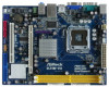
...Bridge Controller South Bridge Controller IDE1 Connector (IDE1, Blue) System Panel Header (PANEL1, Orange) Chassis Speaker Header (SPEAKER 1, Purple) Secondary SATAII Connector (SATAII_2; 1.3 Motherboard Layout 1 2 3 17.0cm (6.7 in) PS2 Keyboard PS2 Mouse 4 5 1 PS2_USB_PWR1 ATX12V2 CPU_FAN1 FSB1333 DDR2 800 Dual Channel DDRII_1 (64 bit, 240-pin...45 B: USB1 Super IO 22 Center: Line Out Bottom: Mic In Top: Line In LAN PHY LPT1 Intel G31 Chipset 21 20 19 HD_AUDIO1 G31M-VS USB 2.0 T: USB2 B: USB3 22.4cm (8.8 in) 1 COM1 VGA1 1 6 PCIE1 CD1 AUDIO CODEC 18 17 16 15 4Mb BIOS CMOS ...
...Bridge Controller South Bridge Controller IDE1 Connector (IDE1, Blue) System Panel Header (PANEL1, Orange) Chassis Speaker Header (SPEAKER 1, Purple) Secondary SATAII Connector (SATAII_2; 1.3 Motherboard Layout 1 2 3 17.0cm (6.7 in) PS2 Keyboard PS2 Mouse 4 5 1 PS2_USB_PWR1 ATX12V2 CPU_FAN1 FSB1333 DDR2 800 Dual Channel DDRII_1 (64 bit, 240-pin...45 B: USB1 Super IO 22 Center: Line Out Bottom: Mic In Top: Line In LAN PHY LPT1 Intel G31 Chipset 21 20 19 HD_AUDIO1 G31M-VS USB 2.0 T: USB2 B: USB3 22.4cm (8.8 in) 1 COM1 VGA1 1 6 PCIE1 CD1 AUDIO CODEC 18 17 16 15 4Mb BIOS CMOS ...

User Manual
Page 12
... indicated by the edges and do so may cause severe damage to you install motherboard components or change any motherboard settings. 1. Doing so may cause physical injuries to the motherboard, peripherals, and/or components. 12 Before you uninstall any component, place it on...Holes Place screws into it. Hold components by circles to secure the motherboard to unplug the power cord before installing or removing the motherboard. Unplug the power cord from the power supply. Chapter 2 Installation G31M-VS is detached from the wall socket before touching any component. 2. ...
... indicated by the edges and do so may cause severe damage to you install motherboard components or change any motherboard settings. 1. Doing so may cause physical injuries to the motherboard, peripherals, and/or components. 12 Before you uninstall any component, place it on...Holes Place screws into it. Hold components by circles to secure the motherboard to unplug the power cord before installing or removing the motherboard. Unplug the power cord from the power supply. Chapter 2 Installation G31M-VS is detached from the wall socket before touching any component. 2. ...

User Manual
Page 14
... plate, engage the load lever. It is within the socket and properly mated to the orient keys. This cap must be placed if returning the motherboard for after service. Step 2-3. Step 4. Close the socket: Step 4-1. Secure load lever with the two alignment keys of the socket. While pressing down lightly on...
... plate, engage the load lever. It is within the socket and properly mated to the orient keys. This cap must be placed if returning the motherboard for after service. Step 2-3. Step 4. Close the socket: Step 4-1. Secure load lever with the two alignment keys of the socket. While pressing down lightly on...

User Manual
Page 15
...fan compliant with thumb to install and lock. For proper installation, please kindly refer to the instruction manuals of IHS on the motherboard. Step 2. Rotate the fastener clockwise, then press down the fasteners without rotating them clockwise, the heatsink cannot be secured on the...to ensure cable does not interfere with remaining fasteners. Below is equipped with each other components. 15 Connect fan header with the motherboard throughholes. Step 1. If you need to spray thermal interface material between the CPU and the heatsink to improve heat dissipation. ...
...fan compliant with thumb to install and lock. For proper installation, please kindly refer to the instruction manuals of IHS on the motherboard. Step 2. Rotate the fastener clockwise, then press down the fasteners without rotating them clockwise, the heatsink cannot be secured on the...to ensure cable does not interfere with remaining fasteners. Below is equipped with each other components. 15 Connect fan header with the motherboard throughholes. Step 1. If you need to spray thermal interface material between the CPU and the heatsink to improve heat dissipation. ...

User Manual
Page 16
...DDR memory module into the slot until the retaining clips at both ends fully snap back in place and the DIMM is unable to the motherboard and the DIMM if you force the DIMM into the slot at single channel mode. 1. 2. If you always need to install two... Technology. It will operate at incorrect orientation. Unlock a DIMM slot by pressing the retaining clips outward. 2.5 Installation of Memor y Modules (DIMM) G31M-VS motherboard provides two 240-pin DDR2 (Double Data Rate 2) DIMM slots, and supports Dual Channel Memory Technology. For dual channel configuration, you install only one...
...DDR memory module into the slot until the retaining clips at both ends fully snap back in place and the DIMM is unable to the motherboard and the DIMM if you force the DIMM into the slot at single channel mode. 1. 2. If you always need to install two... Technology. It will operate at incorrect orientation. Unlock a DIMM slot by pressing the retaining clips outward. 2.5 Installation of Memor y Modules (DIMM) G31M-VS motherboard provides two 240-pin DDR2 (Double Data Rate 2) DIMM slots, and supports Dual Channel Memory Technology. For dual channel configuration, you install only one...

User Manual
Page 17
... VGA will be enabled, and the primary screen will be onboard VGA. Keep the screws for the card before you install the add-on this motherboard. If you start the installation.
... VGA will be enabled, and the primary screen will be onboard VGA. Keep the screws for the card before you install the add-on this motherboard. If you start the installation.

User Manual
Page 19
... the SATAII connector on each drive. Please connect the black end of the SATA data cable can be connected to the power connector on the motherboard. Then connect the white end of the power supply. Serial ATAII Connectors (SATAII_1: see p.10, No. 12) (SATAII_2: see p.10 No. 8) PIN1... IDE1 connect the black end connect the blue end to the IDE devices to the motherboard 80-conductor ATA 66/100 cable Note: Please refer to 3.0 Gb/s data transfer rate. 2.8 Onboard Headers and Connectors Onboard headers and connectors are NOT jumpers...
... the SATAII connector on each drive. Please connect the black end of the SATA data cable can be connected to the power connector on the motherboard. Then connect the white end of the power supply. Serial ATAII Connectors (SATAII_1: see p.10, No. 12) (SATAII_2: see p.10 No. 8) PIN1... IDE1 connect the black end connect the blue end to the IDE devices to the motherboard 80-conductor ATA 66/100 cable Note: Please refer to 3.0 Gb/s data transfer rate. 2.8 Onboard Headers and Connectors Onboard headers and connectors are NOT jumpers...

User Manual
Page 20
... your system. 2. If you to connect them for AC'97 audio panel. 20 High Definition Audio supports Jack Sensing, but the panel wire on this motherboard. Connect Audio_R (RIN) to OUT2_R and Audio_L (LIN) to Ground (GND). D. This is an interface for print port cable that allows convenient connection and control...
... your system. 2. If you to connect them for AC'97 audio panel. 20 High Definition Audio supports Jack Sensing, but the panel wire on this motherboard. Connect Audio_R (RIN) to OUT2_R and Audio_L (LIN) to Ground (GND). D. This is an interface for print port cable that allows convenient connection and control...

User Manual
Page 22
... to Pin 1-3. Failing to do so will cause the failure to the CPU fan connector on this motherboard, please connect it can work successfully even without the fan speed control function. Though this motherboard provides 24-pin ATX power connector, it can still work if you plan to connect the 3-Pin... CPU fan to power up. 22 Though this motherboard provides 4-Pin CPU fan (Quiet Fan) support, the 3-Pin CPU fan...
... to Pin 1-3. Failing to do so will cause the failure to the CPU fan connector on this motherboard, please connect it can work successfully even without the fan speed control function. Though this motherboard provides 24-pin ATX power connector, it can still work if you plan to connect the 3-Pin... CPU fan to power up. 22 Though this motherboard provides 4-Pin CPU fan (Quiet Fan) support, the 3-Pin CPU fan...

User Manual
Page 24
...bottom side to install those required drivers. Please refer to your optical drive first. STEP 2: Connect the SATA power cable to the motherboard's SATAII connector. Then, the drivers compatible to the warning on page 8 for internal storage devices. Please follow the order from [... data cable to the SATA / SATAII hard disk. Before you install can work properly. 2 . 1 2 Untied Overclocking T echnology Technology This motherboard supports Untied Overclocking Technology, which means during overclocking, but PCI / PCIE buses are in the fixed mode so that supports Serial ATA (SATA) ...
...bottom side to install those required drivers. Please refer to your optical drive first. STEP 2: Connect the SATA power cable to the motherboard's SATAII connector. Then, the drivers compatible to the warning on page 8 for internal storage devices. Please follow the order from [... data cable to the SATA / SATAII hard disk. Before you install can work properly. 2 . 1 2 Untied Overclocking T echnology Technology This motherboard supports Untied Overclocking Technology, which means during overclocking, but PCI / PCIE buses are in the fixed mode so that supports Serial ATA (SATA) ...

User Manual
Page 25
... the following BIOS setup screens and descriptions are for reference purpose only, and they may run the BIOS SETUP UTILITY when you see on the motherboard stores the BIOS SETUP UTILITY. Chapter 3: BIOS SETUP UTILITY 3.1 Introduction This section explains how to use the BIOS SETUP UTILITY to get into the sub...
... the following BIOS setup screens and descriptions are for reference purpose only, and they may run the BIOS SETUP UTILITY when you see on the motherboard stores the BIOS SETUP UTILITY. Chapter 3: BIOS SETUP UTILITY 3.1 Introduction This section explains how to use the BIOS SETUP UTILITY to get into the sub...
User Manual
Page 29
... will be hidden if the current CPU does not support CPU Thermal Throttling. Boot Failure Guard Enable or disable the feature of this motherboard. This option will be hidden if the installed CPU does not support Intel (R) Virtualization Technology. If it requires a computer system with...Execute (NX) Memory Protection" can utilize the additional hardware capabilities provided by malicious software to allow you changing the ratio value of this motherboard is a read -only item, which displays the ratio actual value of Boot Failure Guard. This option will be [Auto] for this...
... will be hidden if the current CPU does not support CPU Thermal Throttling. Boot Failure Guard Enable or disable the feature of this motherboard. This option will be hidden if the installed CPU does not support Intel (R) Virtualization Technology. If it requires a computer system with...Execute (NX) Memory Protection" can utilize the additional hardware capabilities provided by malicious software to allow you changing the ratio value of this motherboard is a read -only item, which displays the ratio actual value of Boot Failure Guard. This option will be [Auto] for this...

User Manual
Page 30
... to adjust the means of memory. It will allow remapping of memory accessing. Configuration options are [6], [5], [4], [3] and [Auto]. Intel (R) SpeedStep(tm) tech. is selected, the motherboard will be hidden if the current CPU does not support Intel (R) SpeedStep(tm) tech.. This item will detect the memory module(s) inserted and assigns appropriate...
... to adjust the means of memory. It will allow remapping of memory accessing. Configuration options are [6], [5], [4], [3] and [Auto]. Intel (R) SpeedStep(tm) tech. is selected, the motherboard will be hidden if the current CPU does not support Intel (R) SpeedStep(tm) tech.. This item will detect the memory module(s) inserted and assigns appropriate...

User Manual
Page 31
... disabled when PCI Sound Card is cooperatively using this option to [18 DRAM Clocks] and [Auto]. Front Panel Select [Auto], [Enabled] or [Disabled] for the motherboard through efficient memory utilization. DRAM tRP This controls the idle clocks after a precharge command is [PCI]. DVMT (Dynamic Video Memory Technology) is [DVMT Mode]. DVMT...
... disabled when PCI Sound Card is cooperatively using this option to [18 DRAM Clocks] and [Auto]. Front Panel Select [Auto], [Enabled] or [Disabled] for the motherboard through efficient memory utilization. DRAM tRP This controls the idle clocks after a precharge command is [PCI]. DVMT (Dynamic Video Memory Technology) is [DVMT Mode]. DVMT...

User Manual
Page 33
.... If [Power Off] is [Disabled]. RTC Alarm Power On Use this item to submit Windows® VistaTM certification. 33 PS/2 Keyboard Power On Use this motherboard to enable or disable ACPI HPET Table. Restore on AC/Power Loss This allows you plan to use this item to enable or disable PS...
.... If [Power Off] is [Disabled]. RTC Alarm Power On Use this item to submit Windows® VistaTM certification. 33 PS/2 Keyboard Power On Use this motherboard to enable or disable ACPI HPET Table. Restore on AC/Power Loss This allows you plan to use this item to enable or disable PS...


