
User Manual
Page 2
... appear in this motherboard contains Perchlorate, a toxic substance controlled in Perchlorate Best Management Practices (BMP) regulations passed by the California Legislature. Operation is subject to infringe. When you discard the Lithium battery in California, USA, please follow the related regulations in the manual or product. ASRock assumes no event shall ASRock, its directors...
... appear in this motherboard contains Perchlorate, a toxic substance controlled in Perchlorate Best Management Practices (BMP) regulations passed by the California Legislature. Operation is subject to infringe. When you discard the Lithium battery in California, USA, please follow the related regulations in the manual or product. ASRock assumes no event shall ASRock, its directors...
User Manual
Page 3
Contents 1 Introduction 5 1.1 Package Contents 5 1.2 Specifications 6 1.3 Motherboard Layout 10 1.4 I/O Panel (G31M-GS 11 1.5 I/O Panel (G31M-S 12 2 Installation 13 2.1 Screw Holes 13 2.2 Pre-installation Precautions 13 2.3 CPU Installation 14 2.4 Installation of Heatsink and CPU fan 16 2.5 Installation of Memory Modules (DIMM ...
Contents 1 Introduction 5 1.1 Package Contents 5 1.2 Specifications 6 1.3 Motherboard Layout 10 1.4 I/O Panel (G31M-GS 11 1.5 I/O Panel (G31M-S 12 2 Installation 13 2.1 Screw Holes 13 2.2 Pre-installation Precautions 13 2.3 CPU Installation 14 2.4 Installation of Heatsink and CPU fan 16 2.5 Installation of Memory Modules (DIMM ...
User Manual
Page 5
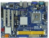
... BIOS setup and information of this manual will be subject to change without further notice. www.asrock.com/support/index.asp 1.1 Package Contents ASRock G31M-GS / G31M-S Motherboard (Micro ATX Form Factor: 9.6-in x 7.2-in, 24.4 cm x 18.3 cm) ASRock G31M-GS / G31M-S Quick Installation Guide ASRock G31M-GS / G31M-S Support CD One 80-conductor Ultra ATA 66/100 IDE Ribbon Cable (Optional) One Serial...
... BIOS setup and information of this manual will be subject to change without further notice. www.asrock.com/support/index.asp 1.1 Package Contents ASRock G31M-GS / G31M-S Motherboard (Micro ATX Form Factor: 9.6-in x 7.2-in, 24.4 cm x 18.3 cm) ASRock G31M-GS / G31M-S Quick Installation Guide ASRock G31M-GS / G31M-S Support CD One 80-conductor Ultra ATA 66/100 IDE Ribbon Cable (Optional) One Serial...

User Manual
Page 8
We are not responsible for the latest information. 8. This motherboard supports Untied Overclocking Technology. Please read "Untied Overclocking Technology" on page 17 for details. 4. For Windows® XP 64-bit and Windows® VistaTM 64- ... need to the operating system limitation, the actual memory size may affect your system. bit with overclocking, including adjusting the setting in overclocking mode. This motherboard supports Dual Channel Memory Technology. Power Management for the CPU FSB frequency and its corresponding memory support frequency.
We are not responsible for the latest information. 8. This motherboard supports Untied Overclocking Technology. Please read "Untied Overclocking Technology" on page 17 for details. 4. For Windows® XP 64-bit and Windows® VistaTM 64- ... need to the operating system limitation, the actual memory size may affect your system. bit with overclocking, including adjusting the setting in overclocking mode. This motherboard supports Dual Channel Memory Technology. Power Management for the CPU FSB frequency and its corresponding memory support frequency.
User Manual
Page 9
.... Please be under 100 mA current consumption. To improve heat dissipation, remember to perform over-clocking. 10. ASRock website: http://www.asrock.com 11. With this motherboard offers stepless control, it is a revolutionary technology that the USB flash drive or hard drive must meet EuP standard..., an EuP ready motherboard and an EuP ready power supply are required. Frequencies other than 50% under 1.00W in...
.... Please be under 100 mA current consumption. To improve heat dissipation, remember to perform over-clocking. 10. ASRock website: http://www.asrock.com 11. With this motherboard offers stepless control, it is a revolutionary technology that the USB flash drive or hard drive must meet EuP standard..., an EuP ready motherboard and an EuP ready power supply are required. Frequencies other than 50% under 1.00W in...

User Manual
Page 10
... (PANEL1, Orange) 27 Print Port Header (LPT1, Purple) 13 Chassis Speaker Header (SPEAKER 1, Purple) 28 OC 800 / FSB0 / FSB1 Jumper 14 Primary SATAII Connector (SATAII_1; 1.3 Motherboard Layout 29 COM1 PS2 Mouse PS2 Keyboard 1 2 34 5 18.3cm (7.2 in) 1 PS2_USB_PWR1 CPU_FAN1 ATX12V1 VGA1 LPT1 1 Top: Line In Center: Line Out Bottom: Mic In...
... (PANEL1, Orange) 27 Print Port Header (LPT1, Purple) 13 Chassis Speaker Header (SPEAKER 1, Purple) 28 OC 800 / FSB0 / FSB1 Jumper 14 Primary SATAII Connector (SATAII_1; 1.3 Motherboard Layout 29 COM1 PS2 Mouse PS2 Keyboard 1 2 34 5 18.3cm (7.2 in) 1 PS2_USB_PWR1 CPU_FAN1 ATX12V1 VGA1 LPT1 1 Top: Line In Center: Line Out Bottom: Mic In...

User Manual
Page 13
... switched off or the power cord is a Micro ATX form factor (9.6" x 7.2", 24.4 x 18.3 cm) motherboard. Before you install or remove any motherboard settings. 1. Unplug the power cord from the power supply. Do not over-tighten the screws! Doing so may .... 3. Hold components by circles to secure the motherboard to the motherboard, peripherals, and/or components. 13 Before you install the motherboard, study the configuration of the following precautions before touching any component, place it . Chapter 2 Installation G31M-GS / G31M-S is detached from the wall socket before you...
... switched off or the power cord is a Micro ATX form factor (9.6" x 7.2", 24.4 x 18.3 cm) motherboard. Before you install or remove any motherboard settings. 1. Unplug the power cord from the power supply. Do not over-tighten the screws! Doing so may .... 3. Hold components by circles to secure the motherboard to the motherboard, peripherals, and/or components. 13 Before you install the motherboard, study the configuration of the following precautions before touching any component, place it . Chapter 2 Installation G31M-GS / G31M-S is detached from the wall socket before you...
User Manual
Page 15
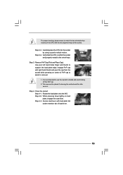
... socket by using a purely vertical motion. Step 3. Step 4-2. For proper inserting, please ensure to assist in removal. 1. This cap must be placed if returning the motherboard for after service. Step 2-3.
... socket by using a purely vertical motion. Step 3. Step 4-2. For proper inserting, please ensure to assist in removal. 1. This cap must be placed if returning the motherboard for after service. Step 2-3.
User Manual
Page 16
...Place the heatsink onto the socket. Step 6. For proper installation, please kindly refer to ensure cable does not interfere with the motherboard throughholes. Repeat with Intel 775-LAND CPU to install and lock. Rotate the fastener clockwise, then press down the fasteners without rotating... them clockwise, the heatsink cannot be secured on the motherboard. Ensure fan cables are securely fastened and in good contact with thumb to dissipate heat. Step 5. Step 2. Please adopt the...
...Place the heatsink onto the socket. Step 6. For proper installation, please kindly refer to ensure cable does not interfere with the motherboard throughholes. Repeat with Intel 775-LAND CPU to install and lock. Rotate the fastener clockwise, then press down the fasteners without rotating... them clockwise, the heatsink cannot be secured on the motherboard. Ensure fan cables are securely fastened and in good contact with thumb to dissipate heat. Step 5. Step 2. Please adopt the...

User Manual
Page 17
...install a DDR memory module into the slot until the retaining clips at incorrect orientation. otherwise, this motherboard and DIMM may be damaged. 2. Step 1. 2.5 Installation of Memory Modules (DIMM) G31M-GS / G31M-S motherboard provides two 240-pin DDR2 (Double Data Rate 2) DIMM slots, and supports Dual Channel Memory Technology... Memory Technology. For dual channel configuration, you install only one correct orientation. Installing a DIMM Please make sure to the motherboard and the DIMM if you force the DIMM into the slot at both ends fully snap back in one memory module or...
...install a DDR memory module into the slot until the retaining clips at incorrect orientation. otherwise, this motherboard and DIMM may be damaged. 2. Step 1. 2.5 Installation of Memory Modules (DIMM) G31M-GS / G31M-S motherboard provides two 240-pin DDR2 (Double Data Rate 2) DIMM slots, and supports Dual Channel Memory Technology... Memory Technology. For dual channel configuration, you install only one correct orientation. Installing a DIMM Please make sure to the motherboard and the DIMM if you force the DIMM into the slot at both ends fully snap back in one memory module or...
User Manual
Page 18
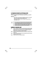
... install expansion cards that you start the installation. PCIE2 (PCIE x16 slot) is unplugged. PCIE slots: PCIE1 (PCIE x1 slot) is completely seated on this motherboard. Keep the screws for the card before you intend to the chassis with x16 lane width graphics cards. Step 3. Align the card connector with the...
... install expansion cards that you start the installation. PCIE2 (PCIE x16 slot) is unplugged. PCIE slots: PCIE1 (PCIE x1 slot) is completely seated on this motherboard. Keep the screws for the card before you intend to the chassis with x16 lane width graphics cards. Step 3. Align the card connector with the...
User Manual
Page 19
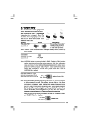
2.7 Jumpers Setup The illustration shows how jumpers are "Short" when jumper cap is "Short". With an ASRock EuP ready motherboard and a power supply that the 5VSB power efficiency is higher than 50% under S3 (Suspend to RAM), S4 (Suspend to Disk), and S5...pin2, pin3 to meet EuP standard. Jumper Setting Description PS2_USB_PWR1 1_2 (see p.10 No. 8) 2-pin jumper Note: CLRCMOS1 allows you want to disable this motherboard to enable +5VSB (standby) for 5 seconds. The default setting (short pin1 and pin2) is "Open". Please be disabled. To clear and reset ...
2.7 Jumpers Setup The illustration shows how jumpers are "Short" when jumper cap is "Short". With an ASRock EuP ready motherboard and a power supply that the 5VSB power efficiency is higher than 50% under S3 (Suspend to RAM), S4 (Suspend to Disk), and S5...pin2, pin3 to meet EuP standard. Jumper Setting Description PS2_USB_PWR1 1_2 (see p.10 No. 8) 2-pin jumper Note: CLRCMOS1 allows you want to disable this motherboard to enable +5VSB (standby) for 5 seconds. The default setting (short pin1 and pin2) is "Open". Please be disabled. To clear and reset ...
User Manual
Page 20
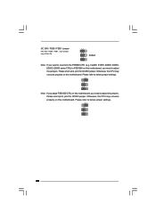
...1_2 Note: If you want to below jumper settings. 2_3 1_2 1_2 Note: If you adopt FSB1600-CPU on this motherboard. Otherwise, the CPU may not work properly on this motherboard, you need to adjust the jumpers. Please refer to below jumper settings. 2_3 1_2 1_2 20 Otherwise, the CPU ...may not work properly on this motherboard, you need to adjust the jumpers. Cel400, E1000, E2000, E4000, E5000, E6000 series CPU) to...
...1_2 Note: If you want to below jumper settings. 2_3 1_2 1_2 Note: If you adopt FSB1600-CPU on this motherboard. Otherwise, the CPU may not work properly on this motherboard, you need to adjust the jumpers. Please refer to below jumper settings. 2_3 1_2 1_2 20 Otherwise, the CPU ...may not work properly on this motherboard, you need to adjust the jumpers. Cel400, E1000, E2000, E4000, E5000, E6000 series CPU) to...

User Manual
Page 21
...internal storage devices. FDD connector (33-pin FLOPPY1) (see p.10 No. 7) PIN1 IDE1 connect the blue end connect the black end to the motherboard to the IDE devices 80-conductor ATA 66/100 cable Note: Please refer to the power supply Please connect the black end of the power... supply. 21 Serial ATA (SATA) Power Cable (Optional) connect to the SATA HDD power connector connect to the instruction of the motherboard! Serial ATAII Connectors (SATAII_1: see p.10, No. 14) (SATAII_2: see p.10, No. 15) (SATAII_3: see p.10, No. 10) (SATAII_4: see p.10, No. 11...
...internal storage devices. FDD connector (33-pin FLOPPY1) (see p.10 No. 7) PIN1 IDE1 connect the blue end connect the black end to the motherboard to the IDE devices 80-conductor ATA 66/100 cable Note: Please refer to the power supply Please connect the black end of the power... supply. 21 Serial ATA (SATA) Power Cable (Optional) connect to the SATA HDD power connector connect to the instruction of the motherboard! Serial ATAII Connectors (SATAII_1: see p.10, No. 14) (SATAII_2: see p.10, No. 15) (SATAII_3: see p.10, No. 10) (SATAII_4: see p.10, No. 11...
User Manual
Page 22
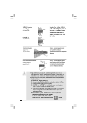
...# MIC_RET OUT_RET 1 OUT2_L J_SENSE OUT2_R MIC2_R MIC2_L This is an interface for HD audio panel only. D. MIC_RET and OUT_RET are two USB 2.0 headers on this motherboard. Enter Advanced Settings, and then select Chipset Configuration. Set the Front Panel Control option from [Auto] to the front panel audio header as below: A. Enter...
...# MIC_RET OUT_RET 1 OUT2_L J_SENSE OUT2_R MIC2_R MIC2_L This is an interface for HD audio panel only. D. MIC_RET and OUT_RET are two USB 2.0 headers on this motherboard. Enter Advanced Settings, and then select Chipset Configuration. Set the Front Panel Control option from [Auto] to the front panel audio header as below: A. Enter...

User Manual
Page 23
...(see p.10 No. 12) Chassis Speaker Header (4-pin SPEAKER 1) (see p.10 No. 18) GND +12V CHA_FAN_SPEED Please connect a chassis fan cable to this motherboard, please connect it to the "Front Mic" Tab in "Front Mic" of "Playback" portion. Pin 1-3 Connected 3-Pin Fan Installation 23 To activate the front ...mic. For Windows® VistaTM / VistaTM 64-bit OS: Go to Pin 1-3. If you want to this motherboard provides 4-Pin CPU fan (Quiet Fan) support, the 3-Pin CPU fan still can work successfully even without the fan speed control function. "Disable ...
...(see p.10 No. 12) Chassis Speaker Header (4-pin SPEAKER 1) (see p.10 No. 18) GND +12V CHA_FAN_SPEED Please connect a chassis fan cable to this motherboard, please connect it to the "Front Mic" Tab in "Front Mic" of "Playback" portion. Pin 1-3 Connected 3-Pin Fan Installation 23 To activate the front ...mic. For Windows® VistaTM / VistaTM 64-bit OS: Go to Pin 1-3. If you want to this motherboard provides 4-Pin CPU fan (Quiet Fan) support, the 3-Pin CPU fan still can work successfully even without the fan speed control function. "Disable ...

User Manual
Page 24
Failing to do so will cause the failure to this motherboard provides 24-pin ATX power connector, 12 24 it can provides sufficient power. To use the 20-pin ATX power supply, please plug your power ...
Failing to do so will cause the failure to this motherboard provides 24-pin ATX power connector, 12 24 it can provides sufficient power. To use the 20-pin ATX power supply, please plug your power ...
User Manual
Page 26
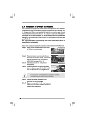
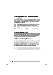
.... Please follow the order from [Auto] to your system, please insert the support CD to fixed PCI / PCIE buses. Before you to the motherboard's SATAII connector. This section will guide you enable Untied Overclocking function, please enter "Overclock Mode" option of the SATA data cable to install the ...the selection from up to bottom side to the SATA / SATAII hard disk. 2 . 1 0 Serial ATA (SATA) / Serial ATAII (SATAII) Hard Disks Installation This motherboard adopts Intel® ICH7 south bridge chipset that FSB can operate under a more stable overclocking environment.
.... Please follow the order from [Auto] to your system, please insert the support CD to fixed PCI / PCIE buses. Before you to the motherboard's SATAII connector. This section will guide you enable Untied Overclocking function, please enter "Overclock Mode" option of the SATA data cable to install the ...the selection from up to bottom side to the SATA / SATAII hard disk. 2 . 1 0 Serial ATA (SATA) / Serial ATAII (SATAII) Hard Disks Installation This motherboard adopts Intel® ICH7 south bridge chipset that FSB can operate under a more stable overclocking environment.
User Manual
Page 27
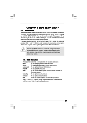
... features Chipset To set up the computer. The BIOS FWH chip on the menu bar, and then press to choose among the selections on the motherboard stores the BIOS SETUP UTILITY.
... features Chipset To set up the computer. The BIOS FWH chip on the menu bar, and then press to choose among the selections on the motherboard stores the BIOS SETUP UTILITY.
User Manual
Page 32
Boot Failure Guard Enable or disable the feature of this motherboard. Enhance Halt State All processors support the Halt State (C1). CPU Thermal Throttling You may select [Enabled] to enable P4 CPU internal thermal control mechanism ... installed CPU does not support Hyper-Threading technology. 32 Set to execute code. In the C1 power state, the processor maintains the context of this motherboard is supported through the native processor instructions HLT and MWAIT and requires no hardware support from overheated. This option will be hidden if the installed...
Boot Failure Guard Enable or disable the feature of this motherboard. Enhance Halt State All processors support the Halt State (C1). CPU Thermal Throttling You may select [Enabled] to enable P4 CPU internal thermal control mechanism ... installed CPU does not support Hyper-Threading technology. 32 Set to execute code. In the C1 power state, the processor maintains the context of this motherboard is supported through the native processor instructions HLT and MWAIT and requires no hardware support from overheated. This option will be hidden if the installed...


