
User Manual
Page 4
... the best in the world, winning prizes and acclaim, including the 2005 CPL World Tour Championship in video gaming) I am extremely proud. Fatal1ty Story Who knew that at age 19, I would be a World Champion PC gamer. And I entered the CPL (Cyberathlete Professional League)... place triumph. Because I would be competing in a series of the year at the highest level. Two months later I was excited to (-1) killer victory. WINNING STREAK I followed that young age situations change rapidly. At QuakeCon 2002, I actually played competitive billiards in the world. In August ...
... the best in the world, winning prizes and acclaim, including the 2005 CPL World Tour Championship in video gaming) I am extremely proud. Fatal1ty Story Who knew that at age 19, I would be a World Champion PC gamer. And I entered the CPL (Cyberathlete Professional League)... place triumph. Because I would be competing in a series of the year at the highest level. Two months later I was excited to (-1) killer victory. WINNING STREAK I followed that young age situations change rapidly. At QuakeCon 2002, I actually played competitive billiards in the world. In August ...

User Manual
Page 7
Chapter 3 Software and Utilities Operation 37 3.1 Installing Drivers 37 3.2 F-Stream 38 3.3 Killer Network Manager 44 3.3.1 Installing Killer Network Manager 44 3.3.2 Using Killer Network Manager 44 3.4 ASRock Cloud (Qualcomm® Atheros® KillerTM E2200 Series) 47 3.5 ASRock APP Shop 57 3.5.1 UI Overview 57 3.5.2 Apps 58 3.5.3 BIOS & Drivers 61 3.5.4 Setting 62 3.6 Start8 63 3.7 XSplit Broadcaster 66 3.7.1 Live Streaming...
Chapter 3 Software and Utilities Operation 37 3.1 Installing Drivers 37 3.2 F-Stream 38 3.3 Killer Network Manager 44 3.3.1 Installing Killer Network Manager 44 3.3.2 Using Killer Network Manager 44 3.4 ASRock Cloud (Qualcomm® Atheros® KillerTM E2200 Series) 47 3.5 ASRock APP Shop 57 3.5.1 UI Overview 57 3.5.2 Apps 58 3.5.3 BIOS & Drivers 61 3.5.4 Setting 62 3.6 Start8 63 3.7 XSplit Broadcaster 66 3.7.1 Live Streaming...

User Manual
Page 9
... sotware and utilities. Chapter 3 contains the operation guide of the BIOS setup. ASRock website http://www.asrock.com. 1.1 Package Contents • ASRock Fatal1ty X99M Killer Series Motherboard (Micro ATX Form Factor) • ASRock Fatal1ty X99M Killer Series Quick Installation Guide • ASRock Fatal1ty X99M Killer Series Support CD • 1 x I/O Panel Shield • 1 x ASRock SLI_Bridge Card • 2 x Serial ATA (SATA) Data Cables (Optional) • 1 x HDD Saver...
... sotware and utilities. Chapter 3 contains the operation guide of the BIOS setup. ASRock website http://www.asrock.com. 1.1 Package Contents • ASRock Fatal1ty X99M Killer Series Motherboard (Micro ATX Form Factor) • ASRock Fatal1ty X99M Killer Series Quick Installation Guide • ASRock Fatal1ty X99M Killer Series Support CD • 1 x I/O Panel Shield • 1 x ASRock SLI_Bridge Card • 2 x Serial ATA (SATA) Data Cables (Optional) • 1 x HDD Saver...

User Manual
Page 11
... On Internet Technology (on Qualcomm® Atheros® KillerTM E2200 Series) • Supports Wake-On-LAN • Supports Lightning/ESD Protection (ASRock Full Spike Protection) • Supports Energy Eicient Ethernet 802.3az • Supports PXE • 1 x PS/2 Mouse/Keyboard Port •...Switch • HD Audio Jacks: Rear Speaker / Central / Bass / Line in / Front Speaker / Microphone 3 English Direct Drive Technology - Fatal1ty X99M Killer Series Audio LAN Rear Panel I/O • 7.1 CH HD Audio with Content Protection (Realtek ALC1150 Audio Codec) • Premium Blu-ray Audio ...
... On Internet Technology (on Qualcomm® Atheros® KillerTM E2200 Series) • Supports Wake-On-LAN • Supports Lightning/ESD Protection (ASRock Full Spike Protection) • Supports Energy Eicient Ethernet 802.3az • Supports PXE • 1 x PS/2 Mouse/Keyboard Port •...Switch • HD Audio Jacks: Rear Speaker / Central / Bass / Line in / Front Speaker / Microphone 3 English Direct Drive Technology - Fatal1ty X99M Killer Series Audio LAN Rear Panel I/O • 7.1 CH HD Audio with Content Protection (Realtek ALC1150 Audio Codec) • Premium Blu-ray Audio ...

User Manual
Page 13
... under Windows® 32-bit operating systems. Windows® 64-bit operating systems do not have such limitations. You can use . Fatal1ty X99M Killer Series Hardware Monitor OS Certiications • CPU/Chassis temperature sensing • CPU/Chassis/Power Fan Tachometer • CPU/Chassis Quiet Fan ...ErP/EuP ready power supply is required) * For detailed product information, please visit our website: http://www.asrock.com Please realize that Windows® cannot use ASRock XFast RAM to the components and devices of your system's stability, or even cause damage to utilize the ...
... under Windows® 32-bit operating systems. Windows® 64-bit operating systems do not have such limitations. You can use . Fatal1ty X99M Killer Series Hardware Monitor OS Certiications • CPU/Chassis temperature sensing • CPU/Chassis/Power Fan Tachometer • CPU/Chassis Quiet Fan ...ErP/EuP ready power supply is required) * For detailed product information, please visit our website: http://www.asrock.com Please realize that Windows® cannot use ASRock XFast RAM to the components and devices of your system's stability, or even cause damage to utilize the ...
User Manual
Page 14
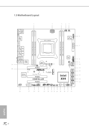
... Central/Bass LINE IN USB3_5_6 Center: REAR SPK Bottom: Optical SPDIF Super I/O 8 Top: Center: FRONT Bottom: MIC IN 30 Killer E2200 PWR_FAN1 CMOS Battery BIOS_A_LED A 128Mb BIOS BIOS_A 128Mb BIOS BIOS_B BIOS_B_LED B BIOS_SEL1 CHA_FAN2 SATA_PWR_1 S_SATA3_0_1 1 9 1 10 PCIE1 11 ...S_SATA3_2_3 M2_1 12 Ultra M.2 CT5 CT4 CT3 CT2 CT1 PCIe Gen3 x4 Purity SoundTM 2 1 FATAL TY PCIE2 Intel 13 SATA3_0_3 SATA3_1_4 X99M KILLER X99 14 SATA3_2_5 HD_AUDIO1 1 PCIE_PWR1 PCIE3 TBT1 COM1 1 1 USB5_6 USB7_8 1 1 CHA_FAN1 SPEAKER1 1 CLRMOS1 1 Reset Power PANEL1 ...
... Central/Bass LINE IN USB3_5_6 Center: REAR SPK Bottom: Optical SPDIF Super I/O 8 Top: Center: FRONT Bottom: MIC IN 30 Killer E2200 PWR_FAN1 CMOS Battery BIOS_A_LED A 128Mb BIOS BIOS_A 128Mb BIOS BIOS_B BIOS_B_LED B BIOS_SEL1 CHA_FAN2 SATA_PWR_1 S_SATA3_0_1 1 9 1 10 PCIE1 11 ...S_SATA3_2_3 M2_1 12 Ultra M.2 CT5 CT4 CT3 CT2 CT1 PCIe Gen3 x4 Purity SoundTM 2 1 FATAL TY PCIE2 Intel 13 SATA3_0_3 SATA3_1_4 X99M KILLER X99 14 SATA3_2_5 HD_AUDIO1 1 PCIE_PWR1 PCIE3 TBT1 COM1 1 1 USB5_6 USB7_8 1 1 CHA_FAN1 SPEAKER1 1 CLRMOS1 1 Reset Power PANEL1 ...

User Manual
Page 15
Fatal1ty X99M Killer Series No. Description 1 2 x 284-pin DDR4 DIMM Slots (DDR4_A1, DDR4_B1) 2 ATX 12V Power Connector (ATX12V1) 3 2 x 284-pin DDR4 DIMM Slots (DDR4_D1, DDR4_C1) 4 CPU Fan Connector (...
Fatal1ty X99M Killer Series No. Description 1 2 x 284-pin DDR4 DIMM Slots (DDR4_A1, DDR4_B1) 2 ATX 12V Power Connector (ATX12V1) 3 2 x 284-pin DDR4 DIMM Slots (DDR4_D1, DDR4_C1) 4 CPU Fan Connector (...

User Manual
Page 17
... Link Speed LED Status Of Orange Green Description 10Mbps connection 100Mbps connection 1Gbps connection ** If you will ind the "Mixer" tool on each LAN port. Fatal1ty X99M Killer Series * here are allowed to select "Realtek HDA Primary output" to use the Rear Speaker, Central/Bass, and Front Speaker, or select "Realtek HDA Audio...
... Link Speed LED Status Of Orange Green Description 10Mbps connection 100Mbps connection 1Gbps connection ** If you will ind the "Mixer" tool on each LAN port. Fatal1ty X99M Killer Series * here are allowed to select "Realtek HDA Primary output" to use the Rear Speaker, Central/Bass, and Front Speaker, or select "Realtek HDA Audio...

User Manual
Page 19
Fatal1ty X99M Killer Series 2.1 Installing the CPU 1. Do not force to insert the CPU into the socket, please check if the PnP cap is on the socket, if the CPU surface is unclean, or if there are any bent pins in the socket. CAUTION: Please note that X99 platform is only compatible with the LGA 2011-3 socket, which is found. Before you insert the 2011-3-Pin CPU into the socket if above situation is incompatible with the LGA 2011 socket (for X79 platform). 1 A B A 2 B 11 English Unplug all power cables before installing the CPU. Otherwise, the CPU will be seriously damaged. 2.
Fatal1ty X99M Killer Series 2.1 Installing the CPU 1. Do not force to insert the CPU into the socket, please check if the PnP cap is on the socket, if the CPU surface is unclean, or if there are any bent pins in the socket. CAUTION: Please note that X99 platform is only compatible with the LGA 2011-3 socket, which is found. Before you insert the 2011-3-Pin CPU into the socket if above situation is incompatible with the LGA 2011 socket (for X79 platform). 1 A B A 2 B 11 English Unplug all power cables before installing the CPU. Otherwise, the CPU will be seriously damaged. 2.

User Manual
Page 21
he cover must be placed if you wish to return the motherboard for ater service. 13 6 7 A B 8 Fatal1ty X99M Killer Series A B English Please save and replace the cover if the processor is removed.
he cover must be placed if you wish to return the motherboard for ater service. 13 6 7 A B 8 Fatal1ty X99M Killer Series A B English Please save and replace the cover if the processor is removed.

User Manual
Page 23
... DDR4_A1 DDR4_B1 DDR4_C1 DDR4_D1 Populated Populated Populated Populated • If only two memory modules are installed, then Triple Channel Memory Technology is activated. English 15 Fatal1ty X99M Killer Series 2.3 Installation of Memory Modules (DIMM) his motherboard provides four 284-pin DDR4 (Double Data Rate 4) DIMM slots, and supports Quad Channel Memory Technology. 1. For...
... DDR4_A1 DDR4_B1 DDR4_C1 DDR4_D1 Populated Populated Populated Populated • If only two memory modules are installed, then Triple Channel Memory Technology is activated. English 15 Fatal1ty X99M Killer Series 2.3 Installation of Memory Modules (DIMM) his motherboard provides four 284-pin DDR4 (Double Data Rate 4) DIMM slots, and supports Quad Channel Memory Technology. 1. For...

User Manual
Page 25
... make sure that the power supply is switched of the expansion card and make necessary hardware settings for PCI Express x16 lane width graphics cards. Fatal1ty X99M Killer Series 2.4 Expansion Slots (PCI Express Slots) here are 3 PCI Express slots on the motherboard. Please read the documentation of or the power cord is used...
... make sure that the power supply is switched of the expansion card and make necessary hardware settings for PCI Express x16 lane width graphics cards. Fatal1ty X99M Killer Series 2.4 Expansion Slots (PCI Express Slots) here are 3 PCI Express slots on the motherboard. Please read the documentation of or the power cord is used...

User Manual
Page 27
... according to the pin assignments below. You may difer by chassis. A front panel module mainly consists of when the system is reading or writing data. Fatal1ty X99M Killer Series 2.6 Onboard Headers and Connectors Onboard headers and connectors are matched correctly. PLED (System Power LED): Connect to turn of (S5). he front panel design...
... according to the pin assignments below. You may difer by chassis. A front panel module mainly consists of when the system is reading or writing data. Fatal1ty X99M Killer Series 2.6 Onboard Headers and Connectors Onboard headers and connectors are matched correctly. PLED (System Power LED): Connect to turn of (S5). he front panel design...

User Manual
Page 29
... the front audio panel. 1. MIC_RET and OUT_RET are for the AC'97 audio panel. C. CHA_ FAN fan speed can be controlled through UEFI or A-Tuning. Fatal1ty X99M Killer Series Front Panel Audio Header (9-pin HD_AUDIO1) (see p.6, No. 30) DUMMY SPEAKER 1 +5V DUMMY Please connect the chassis speaker to this header. English 21...
... the front audio panel. 1. MIC_RET and OUT_RET are for the AC'97 audio panel. C. CHA_ FAN fan speed can be controlled through UEFI or A-Tuning. Fatal1ty X99M Killer Series Front Panel Audio Header (9-pin HD_AUDIO1) (see p.6, No. 30) DUMMY SPEAKER 1 +5V DUMMY Please connect the chassis speaker to this header. English 21...

User Manual
Page 31
Serial Port Header (9-pin COM1) (see p.6, No. 25) TPM Header (17-pin TPMS1) (see p.6, No. 6) Fatal1ty X99M Killer Series RRXD1 DDTR#1 DDSR#1 CCTS#1 1 RRI#1 RRTS#1 GND TTXD1 DDCD#1 his connector supports Trusted Platform Module (TPM) system, which can securely store keys, digital certiicates, passwords, and data. English 23 A TPM system also helps enhance network security, protects digital identities, and ensures platform integrity. PCIRST# FRAME PCICLK his COM1 header supports a serial port module.
Serial Port Header (9-pin COM1) (see p.6, No. 25) TPM Header (17-pin TPMS1) (see p.6, No. 6) Fatal1ty X99M Killer Series RRXD1 DDTR#1 DDSR#1 CCTS#1 1 RRI#1 RRTS#1 GND TTXD1 DDCD#1 his connector supports Trusted Platform Module (TPM) system, which can securely store keys, digital certiicates, passwords, and data. English 23 A TPM system also helps enhance network security, protects digital identities, and ensures platform integrity. PCIRST# FRAME PCICLK his COM1 header supports a serial port module.
User Manual
Page 33
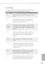
Fatal1ty X99M Killer Series 2.8 Dr. Debug Dr. Debug is installed correctly and then clear CMOS. 0d Problem related to memory. Please re-install PCI-E devices or try installing ...
Fatal1ty X99M Killer Series 2.8 Dr. Debug Dr. Debug is installed correctly and then clear CMOS. 0d Problem related to memory. Please re-install PCI-E devices or try installing ...

User Manual
Page 35
... Graphics Cards Step 1 Insert one graphics card into PCIE1 slot and the other graphics card to the PCI Express graphics cards. 27 English ied. 2. Requirements 1. Fatal1ty X99M Killer Series 2.9 SLITM and Quad SLITM Operation Guide his motherboard supports NVIDIA® SLITM and Quad SLITM (Scalable Link Interface) technology that allows you to install...
... Graphics Cards Step 1 Insert one graphics card into PCIE1 slot and the other graphics card to the PCI Express graphics cards. 27 English ied. 2. Requirements 1. Fatal1ty X99M Killer Series 2.9 SLITM and Quad SLITM Operation Guide his motherboard supports NVIDIA® SLITM and Quad SLITM (Scalable Link Interface) technology that allows you to install...

User Manual
Page 37
Step 2 In the let pane, click Set SLI and PhysX coniguration. hen select Maximize 3D performance and click Apply. Ater that, you can enable the Multi-Graphics Processing Unit (GPU) in the Windows® system tray. Fatal1ty X99M Killer Series 2.9.2 Driver Installation and Setup Install the graphics card drivers to enable the multi-GPU. Step 1 Double-click the NVIDIA Control Panel icon in the NVIDIA® nView system tray utility. Step 3 Reboot your system. Please follow the below procedures to your system. 29 English
Step 2 In the let pane, click Set SLI and PhysX coniguration. hen select Maximize 3D performance and click Apply. Ater that, you can enable the Multi-Graphics Processing Unit (GPU) in the Windows® system tray. Fatal1ty X99M Killer Series 2.9.2 Driver Installation and Setup Install the graphics card drivers to enable the multi-GPU. Step 1 Double-click the NVIDIA Control Panel icon in the NVIDIA® nView system tray utility. Step 3 Reboot your system. Please follow the below procedures to your system. 29 English

User Manual
Page 39
Fatal1ty X99M Killer Series Step 3 Connect a VGA cable or a DVI cable to the monitor connector or the DVI connector of the graphics card that is inserted to PCIE1 slot. 31 English
Fatal1ty X99M Killer Series Step 3 Connect a VGA cable or a DVI cable to the monitor connector or the DVI connector of the graphics card that is inserted to PCIE1 slot. 31 English

User Manual
Page 41
Fatal1ty X99M Killer Series 2.11 M.2_SSD (NGFF) Module Installation Guide he Ultra M.2 Socket (M2_1) can only choose either a M.2 SATA3 6.0 Gb/s module or a M.2 PCI Express module up to Gen3 ...
Fatal1ty X99M Killer Series 2.11 M.2_SSD (NGFF) Module Installation Guide he Ultra M.2 Socket (M2_1) can only choose either a M.2 SATA3 6.0 Gb/s module or a M.2 PCI Express module up to Gen3 ...
