
User Manual
Page 7
... Update & APP Shop 48 3.3.1 UI Overview 48 3.3.2 Apps 49 3.3.3 BIOS & Drivers 52 3.3.4 Setting 53 3.4 Creative SoundBlaster Cinema3 54 3.5 ASRock RGB LED 55 Chapter 4 UEFI SETUP UTILITY 57 4.1 Introduction 57 4.1.1 UEFI Menu Bar 57 4.1.2 Navigation Keys 58 4.2 Main Screen 59 4.3 OC Tweaker Screen 60... Screen 62 4.4.1 CPU Configuration 63 4.4.2 North Bridge Configuration 64 4.4.3 South Bridge Configuration 65 4.4.4 Storage Configuration 66 4.4.5 Super IO Configuration 67 4.4.6 ACPI Configuration 68 4.4.7 USB Configuration 69 4.4.8 Trusted Computing 70
... Update & APP Shop 48 3.3.1 UI Overview 48 3.3.2 Apps 49 3.3.3 BIOS & Drivers 52 3.3.4 Setting 53 3.4 Creative SoundBlaster Cinema3 54 3.5 ASRock RGB LED 55 Chapter 4 UEFI SETUP UTILITY 57 4.1 Introduction 57 4.1.1 UEFI Menu Bar 57 4.1.2 Navigation Keys 58 4.2 Main Screen 59 4.3 OC Tweaker Screen 60... Screen 62 4.4.1 CPU Configuration 63 4.4.2 North Bridge Configuration 64 4.4.3 South Bridge Configuration 65 4.4.4 Storage Configuration 66 4.4.5 Super IO Configuration 67 4.4.6 ACPI Configuration 68 4.4.7 USB Configuration 69 4.4.8 Trusted Computing 70

User Manual
Page 12
...1 x HDMI Port • 1 x Optical SPDIF Out Port • 1 x USB 3.1 Type-A Port (10 Gb/s) (Supports ESD Protection) • 1 x USB 3.1 Type-C Port (10 Gb/s) (Supports ESD Protection) • 6 x USB 3.0 Ports (Supports ESD Protection) * 1 x Fatal1ty Mouse Port (USB 3.0) is included • 1 x RJ-45 LAN Port with LED (ACT/LINK ...2242/2260/2280 M.2 SATA3 6.0 Gb/s module and M.2 PCI Express module up to Gen2 x2 (10 Gb/s)* * Supports NVMe SSD as boot disks * Supports ASRock U.2 Kit Connector • 1 x COM Port Header • 1 x TPM Header • 1 x Power LED and Speaker Header • 1 x...
...1 x HDMI Port • 1 x Optical SPDIF Out Port • 1 x USB 3.1 Type-A Port (10 Gb/s) (Supports ESD Protection) • 1 x USB 3.1 Type-C Port (10 Gb/s) (Supports ESD Protection) • 6 x USB 3.0 Ports (Supports ESD Protection) * 1 x Fatal1ty Mouse Port (USB 3.0) is included • 1 x RJ-45 LAN Port with LED (ACT/LINK ...2242/2260/2280 M.2 SATA3 6.0 Gb/s module and M.2 PCI Express module up to Gen2 x2 (10 Gb/s)* * Supports NVMe SSD as boot disks * Supports ASRock U.2 Kit Connector • 1 x COM Port Header • 1 x TPM Header • 1 x Power LED and Speaker Header • 1 x...
User Manual
Page 13
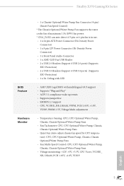
Fatal1ty X370 Gaming K4 Series • 1 x Chassis Optional/Water Pump Fan Connector (4-pin) (Smart Fan Speed Control) * The Chassis Optional/Water Pump Fan supports the water cooler fan of...) • 1 x 8 pin 12V Power Connector (Hi-Density Power Connector) • 1 x Front Panel Audio Connector • 1 x AMD LED Fan USB Header • 2 x USB 2.0 Headers (Support 4 USB 2.0 ports) (Supports ESD Protection) • 2 x USB 3.0 Headers (Support 4 USB 3.0 ports) (Supports ESD Protection) • 1 x Dr. Debug with LED BIOS Feature • AMI UEFI Legal BIOS with multilingual GUI support...
Fatal1ty X370 Gaming K4 Series • 1 x Chassis Optional/Water Pump Fan Connector (4-pin) (Smart Fan Speed Control) * The Chassis Optional/Water Pump Fan supports the water cooler fan of...) • 1 x 8 pin 12V Power Connector (Hi-Density Power Connector) • 1 x Front Panel Audio Connector • 1 x AMD LED Fan USB Header • 2 x USB 2.0 Headers (Support 4 USB 2.0 ports) (Supports ESD Protection) • 2 x USB 3.0 Headers (Support 4 USB 3.0 ports) (Supports ESD Protection) • 1 x Dr. Debug with LED BIOS Feature • AMI UEFI Legal BIOS with multilingual GUI support...
User Manual
Page 15
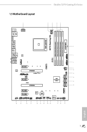
1.3 Motherboard Layout Fatal1ty X370 Gaming K4 Series Bottom: Optical SPDIF 1 2 3 45 CPU_OPT/W_PUMP CPU_FAN1 PS2 Mouse PS2 Keyboard X370 Gaming K4 HDMI1 SOCKET AM4 USB 3.0 T: USB1 B: USB2 USB 3.0 T: USB3 B: USB4 USB 3.1 T: USB3_TA_1 B: USB3_TC_1 USB 3.0 T: USB5 B: USB6 Top: RJ-45 LAN Top: Central... bit, 288-pin module) 6 7 USB3_9_10 1 1 USB_5 1 AMD_FAN_LED1 1 USB3_7_8 8 9 10 CHA_FAN1 11 SATA3_5_6 12 AMD Promontory X370 13 SATA3_3_4 14 ATXPWR1 SATA3_1_2 M2_2 PCIE5 PCIE6 HD_AUDIO1 COM1 1 1 1 TPMS1 SPK_PLED1 1 26 25 24 23 Super I/O CMOS Battery ...
1.3 Motherboard Layout Fatal1ty X370 Gaming K4 Series Bottom: Optical SPDIF 1 2 3 45 CPU_OPT/W_PUMP CPU_FAN1 PS2 Mouse PS2 Keyboard X370 Gaming K4 HDMI1 SOCKET AM4 USB 3.0 T: USB1 B: USB2 USB 3.0 T: USB3 B: USB4 USB 3.1 T: USB3_TA_1 B: USB3_TC_1 USB 3.0 T: USB5 B: USB6 Top: RJ-45 LAN Top: Central... bit, 288-pin module) 6 7 USB3_9_10 1 1 USB_5 1 AMD_FAN_LED1 1 USB3_7_8 8 9 10 CHA_FAN1 11 SATA3_5_6 12 AMD Promontory X370 13 SATA3_3_4 14 ATXPWR1 SATA3_1_2 M2_2 PCIE5 PCIE6 HD_AUDIO1 COM1 1 1 1 TPMS1 SPK_PLED1 1 26 25 24 23 Super I/O CMOS Battery ...

User Manual
Page 16
... DIMM Slots (DDR4_A1, DDR4_B1) 5 2 x 288-pin DDR4 DIMM Slots (DDR4_A2, DDR4_B2) 6 ATX Power Connector (ATXPWR1) 7 USB 3.0 Header (USB3_9_10) 8 USB 3.0 Header (USB3_7_8) 9 AMD LED Fan USB Header (USB_5) 10 AMD Fan LED Header (AMD_FAN_LED1) 11 Chassis Fan Connector (CHA_FAN1) 12 SATA3 Connectors (SATA3_5_6) 13 SATA3 Connectors ...18 Clear CMOS Jumper (CLRMOS1) 19 Chassis Fan / Waterpump Fan Connector (CHA_FAN3/W_PUMP) 20 Chassis Fan Connector (CHA_FAN2) 21 USB 2.0 Header (USB_1_2) 22 USB 2.0 Header (USB_3_4) 23 Power LED and Speaker Header (SPK_PLED1) 24 TPM Header (TPMS1) 25 COM Port Header (COM1...
... DIMM Slots (DDR4_A1, DDR4_B1) 5 2 x 288-pin DDR4 DIMM Slots (DDR4_A2, DDR4_B2) 6 ATX Power Connector (ATXPWR1) 7 USB 3.0 Header (USB3_9_10) 8 USB 3.0 Header (USB3_7_8) 9 AMD LED Fan USB Header (USB_5) 10 AMD Fan LED Header (AMD_FAN_LED1) 11 Chassis Fan Connector (CHA_FAN1) 12 SATA3 Connectors (SATA3_5_6) 13 SATA3 Connectors ...18 Clear CMOS Jumper (CLRMOS1) 19 Chassis Fan / Waterpump Fan Connector (CHA_FAN3/W_PUMP) 20 Chassis Fan Connector (CHA_FAN2) 21 USB 2.0 Header (USB_1_2) 22 USB 2.0 Header (USB_3_4) 23 Power LED and Speaker Header (SPK_PLED1) 24 TPM Header (TPMS1) 25 COM Port Header (COM1...

User Manual
Page 17
... Status Orange Orange Green Description 10Mbps connection 100Mbps connection 1Gbps connection 9 English Description 10 USB 3.1 Type-A Port (USB3_TA_1) 11 USB 3.1 Type-C Port (USB3_TC_1) 12 USB 3.0 Ports (USB3_3_4) 13 Fatal1ty Mouse Port (USB3_1) 14 USB 3.0 Port (USB3_2) 15 HDMI Port (HDMI1) 16 PS/2 Keyboard Port 17 Antenna... / Bass (Orange) 4 Rear Speaker (Black) 5 Line In (Light Blue) 6 Front Speaker (Lime)** 7 Microphone (Pink) 8 Optical SPDIF Out Port 9 USB 3.0 Ports (USB3_5_6) 12 10 9 87 11 No. 1.4 I/O Panel 1 Fatal1ty X370 Gaming K4 Series 35 2 46 17 16 15 13 14 No.
... Status Orange Orange Green Description 10Mbps connection 100Mbps connection 1Gbps connection 9 English Description 10 USB 3.1 Type-A Port (USB3_TA_1) 11 USB 3.1 Type-C Port (USB3_TC_1) 12 USB 3.0 Ports (USB3_3_4) 13 Fatal1ty Mouse Port (USB3_1) 14 USB 3.0 Port (USB3_2) 15 HDMI Port (HDMI1) 16 PS/2 Keyboard Port 17 Antenna... / Bass (Orange) 4 Rear Speaker (Black) 5 Line In (Light Blue) 6 Front Speaker (Lime)** 7 Microphone (Pink) 8 Optical SPDIF Out Port 9 USB 3.0 Ports (USB3_5_6) 12 10 9 87 11 No. 1.4 I/O Panel 1 Fatal1ty X370 Gaming K4 Series 35 2 46 17 16 15 13 14 No.

User Manual
Page 30
If you select USB connector, please install AMD utility "SR3 Settings Software". *The diagram shown here are for the orientation of AMD Fan LED Header (AMD_FAN_LED1) and page 28 for reference only. 6 CPU_FAN1 +12V AMD_FAN_LED1 or 7 CPU_FAN1 AMD_FAN_LED1 USB_5 Please note that only one cable should be used at a time in this step. If you select AMD_FAN_LED1, please install ASRock utility "ASRock RGB LED". Please refer to page 31 for the orientation of AMD LED Fan USB Header (USB_5). 22 English
If you select USB connector, please install AMD utility "SR3 Settings Software". *The diagram shown here are for the orientation of AMD Fan LED Header (AMD_FAN_LED1) and page 28 for reference only. 6 CPU_FAN1 +12V AMD_FAN_LED1 or 7 CPU_FAN1 AMD_FAN_LED1 USB_5 Please note that only one cable should be used at a time in this step. If you select AMD_FAN_LED1, please install ASRock utility "ASRock RGB LED". Please refer to page 31 for the orientation of AMD LED Fan USB Header (USB_5). 22 English

User Manual
Page 36
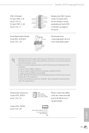
P+ USB_PWR This header is used for internal storage devices with up to this motherboard. USB 2.0 Headers ((9-pin USB_1_2) (see p.7, No. 21) (9-pin USB_3_4) (see p.7, No. 22) USB_PWR PP+ GND DUMMY 1 GND P+ PUSB_PWR There are two headers on ... 6.0 Gb/s data transfer rate. SATA3_6 SATA3_5 These six SATA3 connectors support SATA data cables for connecting the USB connector on this header. Each USB 2.0 header can support two ports. 28 English SATA3_2 SATA3_1 AMD LED Fan USB Header (4-pin USB_5) (see p.7, No. 12) SATA3_3 SATA3_4 SPEAKER DUMMY DUMMY +5V 1 PLED+ PLED+...
P+ USB_PWR This header is used for internal storage devices with up to this motherboard. USB 2.0 Headers ((9-pin USB_1_2) (see p.7, No. 21) (9-pin USB_3_4) (see p.7, No. 22) USB_PWR PP+ GND DUMMY 1 GND P+ PUSB_PWR There are two headers on ... 6.0 Gb/s data transfer rate. SATA3_6 SATA3_5 These six SATA3 connectors support SATA data cables for connecting the USB connector on this header. Each USB 2.0 header can support two ports. 28 English SATA3_2 SATA3_1 AMD LED Fan USB Header (4-pin USB_5) (see p.7, No. 12) SATA3_3 SATA3_4 SPEAKER DUMMY DUMMY +5V 1 PLED+ PLED+...
User Manual
Page 37
... is for the HD audio panel only. Connect Mic_IN (MIC) to Ground (GND). Connect Ground (GND) to MIC2_L. E. Fatal1ty X370 Gaming K4 Series USB 3.0 Header (19-pin USB3_7_8) (see p.7, No. 8) (19-pin USB3_9_10) (see p.7, No. 7) Vbus IntA_PA_SSRXIntA_PA_SSRX+ GND... IntA_PA_SSTXIntA_PA_SSTX+ GND IntA_PA_DIntA_PA_D+ Vbus IntA_PB_SSRXIntA_PB_SSRX+ GND IntA_PB_SSTXIntA_PB_SSTX+ GND IntA_PB_DIntA_PB_D+ Dummy 1 Besides four USB 3.0 ports on the I/O panel, there are for connecting audio devices to the front audio panel. 1. MIC_RET and OUT_RET are...
... is for the HD audio panel only. Connect Mic_IN (MIC) to Ground (GND). Connect Ground (GND) to MIC2_L. E. Fatal1ty X370 Gaming K4 Series USB 3.0 Header (19-pin USB3_7_8) (see p.7, No. 8) (19-pin USB3_9_10) (see p.7, No. 7) Vbus IntA_PA_SSRXIntA_PA_SSRX+ GND... IntA_PA_SSTXIntA_PA_SSTX+ GND IntA_PA_DIntA_PA_D+ Vbus IntA_PB_SSRXIntA_PB_SSRX+ GND IntA_PB_SSTXIntA_PB_SSTX+ GND IntA_PB_DIntA_PB_D+ Dummy 1 Besides four USB 3.0 ports on the I/O panel, there are for connecting audio devices to the front audio panel. 1. MIC_RET and OUT_RET are...
User Manual
Page 40
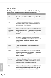
... see the diagrams below for reading the Dr. Debug codes. If the problem still exists, please install only one memory module or try using other USB, PCI devices. 01 - 54 (except 0d), 5A- 60 Problem related to PCI-E devices.
... see the diagrams below for reading the Dr. Debug codes. If the problem still exists, please install only one memory module or try using other USB, PCI devices. 01 - 54 (except 0d), 5A- 60 Problem related to PCI-E devices.

User Manual
Page 41
...or use other memory modules. If the problem still exists, please try using other VGA cards. Fatal1ty X370 Gaming K4 Series b4 Problem related to memory. English 33 b7 Problem related to USB devices. Please clear CMOS and try re-installing the keyboard and mouse. d6 The VGA could not... be recognized. Please try re-installing the VGA card. Please try removing all USB devices. Please re-install the CPU and memory then clear CMOS. d7 The Keyboard and mouse could not be recognized. d8 Invalid ...
...or use other memory modules. If the problem still exists, please try using other VGA cards. Fatal1ty X370 Gaming K4 Series b4 Problem related to memory. English 33 b7 Problem related to USB devices. Please clear CMOS and try re-installing the keyboard and mouse. d6 The VGA could not... be recognized. Please try re-installing the VGA card. Please try removing all USB devices. Please re-install the CPU and memory then clear CMOS. d7 The Keyboard and mouse could not be recognized. d8 Invalid ...

User Manual
Page 70
... In this section may set the configurations for the following items: CPU Configuration, North Bridge Configuration, South Bridge Configuration, StorageConfiguration, Super IO Configuration, ACPI Configuration, USB Configuration and Trusted Computing. Full HD UEFI When [Auto] is selected, the resolution will be set to malfunction.
... In this section may set the configurations for the following items: CPU Configuration, North Bridge Configuration, South Bridge Configuration, StorageConfiguration, Super IO Configuration, ACPI Configuration, USB Configuration and Trusted Computing. Full HD UEFI When [Auto] is selected, the resolution will be set to malfunction.

User Manual
Page 77
USB 3.0 Controller Enable or disable all the USB ports. If you encounter USB compatibility issues it is recommended to support USB devices under the UEFI setup and Windows/Linux operating systems only. XHCI Legacy Support Enable or disable XHCI Controller Legacy support. 69 English Legacy USB Support Enable or disable Legacy OS Support for USB 2.0 devices. Select UEFI Setup Only to disable legacy USB support. 4.4.7 USB Configuration Fatal1ty X370 Gaming K4 Series USB Controller Enable or disable all the USB 3.0 ports.
USB 3.0 Controller Enable or disable all the USB ports. If you encounter USB compatibility issues it is recommended to support USB devices under the UEFI setup and Windows/Linux operating systems only. XHCI Legacy Support Enable or disable XHCI Controller Legacy support. 69 English Legacy USB Support Enable or disable Legacy OS Support for USB 2.0 devices. Select UEFI Setup Only to disable legacy USB support. 4.4.7 USB Configuration Fatal1ty X370 Gaming K4 Series USB Controller Enable or disable all the USB 3.0 ports.

User Manual
Page 79
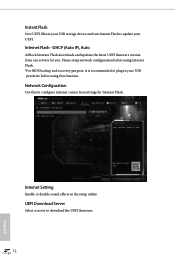
Easy RAID Installer Easy RAID Installer helps you to adjust the RGB LED color to your USB storage device. 4.5 Tools Fatal1ty X370 Gaming K4 Series RGB LED ASRock RGB LED allows you to copy the RAID driver from the support CD to your liking. English 71 After copying the drivers please change the SATA mode to RAID, then you can start installing the operating system in RAID mode.
Easy RAID Installer Easy RAID Installer helps you to adjust the RGB LED color to your USB storage device. 4.5 Tools Fatal1ty X370 Gaming K4 Series RGB LED ASRock RGB LED allows you to copy the RAID driver from the support CD to your liking. English 71 After copying the drivers please change the SATA mode to RAID, then you can start installing the operating system in RAID mode.
User Manual
Page 80
... device and run Instant Flash to configure internet connection settings for you. UEFI Download Server Select a server to plug in your USB pen drive before using Internet Flash. *For BIOS backup and recovery purpose, it is recommended to download the UEFI firmware. 72 ...English Network Configuration Use this function. DHCP (Auto IP), Auto ASRock Internet Flash downloads and updates the latest UEFI firmware version from our servers for Internet Flash. Instant Flash Save UEFI files in your UEFI. ...
... device and run Instant Flash to configure internet connection settings for you. UEFI Download Server Select a server to plug in your USB pen drive before using Internet Flash. *For BIOS backup and recovery purpose, it is recommended to download the UEFI firmware. 72 ...English Network Configuration Use this function. DHCP (Auto IP), Auto ASRock Internet Flash downloads and updates the latest UEFI firmware version from our servers for Internet Flash. Instant Flash Save UEFI files in your UEFI. ...

User Manual
Page 84
... note that a buzzer is needed. Full Screen Logo Enable to display the boot logo or disable to wait for you may not boot from an USB storage device. Boot From Onboard LAN Allow the system to configure the boot settings and the boot priority. In fast mode you to be turned...
... note that a buzzer is needed. Full Screen Logo Enable to display the boot logo or disable to wait for you may not boot from an USB storage device. Boot From Onboard LAN Allow the system to configure the boot settings and the boot priority. In fast mode you to be turned...

Quick Installation Guide
Page 5
Motherboard Layout Fatal1ty X370 Gaming K4 Series Bottom: Optical SPDIF 1 2 3 45 CPU_OPT/W_PUMP CPU_FAN1 PS2 Mouse PS2 Keyboard X370 Gaming K4 HDMI1 SOCKET AM4 USB 3.0 T: USB1 B: USB2 USB 3.0 T: USB3 B: USB4 USB 3.1 T: USB3_TA_1 B: USB3_TC_1 USB 3.0 T: USB5 B: USB6 Top: RJ-45 LAN Top: Central... bit, 288-pin module) 6 7 USB3_9_10 1 1 USB_5 1 AMD_FAN_LED1 1 USB3_7_8 8 9 10 CHA_FAN1 11 SATA3_5_6 12 AMD Promontory X370 13 SATA3_3_4 14 ATXPWR1 SATA3_1_2 M2_2 PCIE5 PCIE6 HD_AUDIO1 COM1 1 1 1 TPMS1 SPK_PLED1 1 26 25 24 23 Super I/O CMOS Battery ...
Motherboard Layout Fatal1ty X370 Gaming K4 Series Bottom: Optical SPDIF 1 2 3 45 CPU_OPT/W_PUMP CPU_FAN1 PS2 Mouse PS2 Keyboard X370 Gaming K4 HDMI1 SOCKET AM4 USB 3.0 T: USB1 B: USB2 USB 3.0 T: USB3 B: USB4 USB 3.1 T: USB3_TA_1 B: USB3_TC_1 USB 3.0 T: USB5 B: USB6 Top: RJ-45 LAN Top: Central... bit, 288-pin module) 6 7 USB3_9_10 1 1 USB_5 1 AMD_FAN_LED1 1 USB3_7_8 8 9 10 CHA_FAN1 11 SATA3_5_6 12 AMD Promontory X370 13 SATA3_3_4 14 ATXPWR1 SATA3_1_2 M2_2 PCIE5 PCIE6 HD_AUDIO1 COM1 1 1 1 TPMS1 SPK_PLED1 1 26 25 24 23 Super I/O CMOS Battery ...

Quick Installation Guide
Page 6
... DIMM Slots (DDR4_A1, DDR4_B1) 5 2 x 288-pin DDR4 DIMM Slots (DDR4_A2, DDR4_B2) 6 ATX Power Connector (ATXPWR1) 7 USB 3.0 Header (USB3_9_10) 8 USB 3.0 Header (USB3_7_8) 9 AMD LED Fan USB Header (USB_5) 10 AMD Fan LED Header (AMD_FAN_LED1) 11 Chassis Fan Connector (CHA_FAN1) 12 SATA3 Connectors (SATA3_5_6) 13 SATA3 Connectors ...18 Clear CMOS Jumper (CLRMOS1) 19 Chassis Fan / Waterpump Fan Connector (CHA_FAN3/W_PUMP) 20 Chassis Fan Connector (CHA_FAN2) 21 USB 2.0 Header (USB_1_2) 22 USB 2.0 Header (USB_3_4) 23 Power LED and Speaker Header (SPK_PLED1) 24 TPM Header (TPMS1) 25 COM Port Header (COM1...
... DIMM Slots (DDR4_A1, DDR4_B1) 5 2 x 288-pin DDR4 DIMM Slots (DDR4_A2, DDR4_B2) 6 ATX Power Connector (ATXPWR1) 7 USB 3.0 Header (USB3_9_10) 8 USB 3.0 Header (USB3_7_8) 9 AMD LED Fan USB Header (USB_5) 10 AMD Fan LED Header (AMD_FAN_LED1) 11 Chassis Fan Connector (CHA_FAN1) 12 SATA3 Connectors (SATA3_5_6) 13 SATA3 Connectors ...18 Clear CMOS Jumper (CLRMOS1) 19 Chassis Fan / Waterpump Fan Connector (CHA_FAN3/W_PUMP) 20 Chassis Fan Connector (CHA_FAN2) 21 USB 2.0 Header (USB_1_2) 22 USB 2.0 Header (USB_3_4) 23 Power LED and Speaker Header (SPK_PLED1) 24 TPM Header (TPMS1) 25 COM Port Header (COM1...

Quick Installation Guide
Page 7
... refer to the table below for the LAN port LED indications. I/O Panel 1 Fatal1ty X370 Gaming K4 Series 35 2 46 17 16 15 13 14 No. Description 10 USB 3.1 Type-A Port (USB3_TA_1) 11 USB 3.1 Type-C Port (USB3_TC_1) 12 USB 3.0 Ports (USB3_3_4) 13 Fatal1ty Mouse Port (USB3_1) 14 USB 3.0 Port (USB3_2) 15 HDMI Port (HDMI1) 16 PS/2 Keyboard Port 17 Antenna...
... refer to the table below for the LAN port LED indications. I/O Panel 1 Fatal1ty X370 Gaming K4 Series 35 2 46 17 16 15 13 14 No. Description 10 USB 3.1 Type-A Port (USB3_TA_1) 11 USB 3.1 Type-C Port (USB3_TC_1) 12 USB 3.0 Ports (USB3_3_4) 13 Fatal1ty Mouse Port (USB3_1) 14 USB 3.0 Port (USB3_2) 15 HDMI Port (HDMI1) 16 PS/2 Keyboard Port 17 Antenna...

Quick Installation Guide
Page 12
... x HDMI Port • 1 x Optical SPDIF Out Port • 1 x USB 3.1 Type-A Port (10 Gb/s) (Supports ESD Protection) • 1 x USB 3.1 Type-C Port (10 Gb/s) (Supports ESD Protection) • 6 x USB 3.0 Ports (Supports ESD Protection) * 1 x Fatal1ty Mouse Port (USB 3.0) is included • 1 x RJ-45 LAN Port with LED (ACT/LINK ...2242/2260/2280 M.2 SATA3 6.0 Gb/s module and M.2 PCI Express module up to Gen2 x2 (10 Gb/s)* * Supports NVMe SSD as boot disks * Supports ASRock U.2 Kit Connector • 1 x COM Port Header • 1 x TPM Header • 1 x Power LED and Speaker Header • 1 x ...
... x HDMI Port • 1 x Optical SPDIF Out Port • 1 x USB 3.1 Type-A Port (10 Gb/s) (Supports ESD Protection) • 1 x USB 3.1 Type-C Port (10 Gb/s) (Supports ESD Protection) • 6 x USB 3.0 Ports (Supports ESD Protection) * 1 x Fatal1ty Mouse Port (USB 3.0) is included • 1 x RJ-45 LAN Port with LED (ACT/LINK ...2242/2260/2280 M.2 SATA3 6.0 Gb/s module and M.2 PCI Express module up to Gen2 x2 (10 Gb/s)* * Supports NVMe SSD as boot disks * Supports ASRock U.2 Kit Connector • 1 x COM Port Header • 1 x TPM Header • 1 x Power LED and Speaker Header • 1 x ...


