

User Manual
Page 2
...Products and corporate names appearing in Perchlorate Best Management Practices (BMP) regulations passed by ASRock. CALIFORNIA, USA ONLY The Lithium battery adopted on this motherboard contains Perchlorate, a toxic substance controlled in this documentation. Disclaimer: Specifications and information ... a particular purpose. "Perchlorate Material-special handling may be constructed as a commitment by the California Legislature. ASRock assumes no event shall ASRock, its directors, officers, employees, or agents be liable for any indirect, special, incidental, or consequential ...
...Products and corporate names appearing in Perchlorate Best Management Practices (BMP) regulations passed by ASRock. CALIFORNIA, USA ONLY The Lithium battery adopted on this motherboard contains Perchlorate, a toxic substance controlled in this documentation. Disclaimer: Specifications and information ... a particular purpose. "Perchlorate Material-special handling may be constructed as a commitment by the California Legislature. ASRock assumes no event shall ASRock, its directors, officers, employees, or agents be liable for any indirect, special, incidental, or consequential ...

User Manual
Page 6
Contents Chapter 1 Introduction 1 1.1 Package Contents 1 1.2 Specifications 2 1.3 Motherboard Layout 6 1.4 I/O Panel 8 Chapter 2 Installation 10 2.1 Installing the CPU 11 2.2 Installing the CPU Fan and Heatsink 14 2.3 Installing Memory Modules (DIMM) 15 2.4 Expansion Slots (PCI Express ...
Contents Chapter 1 Introduction 1 1.1 Package Contents 1 1.2 Specifications 2 1.3 Motherboard Layout 6 1.4 I/O Panel 8 Chapter 2 Installation 10 2.1 Installing the CPU 11 2.2 Installing the CPU Fan and Heatsink 14 2.3 Installing Memory Modules (DIMM) 15 2.4 Expansion Slots (PCI Express ...

User Manual
Page 9
... be subject to quality and endurance. ASRock website http://www.asrock.com. 1.1 Package Contents • ASRock Fatal1ty H170 Performance Series Motherboard (ATX Form Factor) • ASRock Fatal1ty H170 Performance Series Quick Installation Guide • ASRock Fatal1ty H170 Performance Series Support CD • 2 x Serial ATA (SATA) Data Cables (Optional) • 1 x I/O Panel Shield • 1 x Screw for purchasing ASRock Fatal1ty H170 Performance Series motherboard, a reliable motherboard produced under ASRock's consistently stringent quality control. It delivers...
... be subject to quality and endurance. ASRock website http://www.asrock.com. 1.1 Package Contents • ASRock Fatal1ty H170 Performance Series Motherboard (ATX Form Factor) • ASRock Fatal1ty H170 Performance Series Quick Installation Guide • ASRock Fatal1ty H170 Performance Series Support CD • 2 x Serial ATA (SATA) Data Cables (Optional) • 1 x I/O Panel Shield • 1 x Screw for purchasing ASRock Fatal1ty H170 Performance Series motherboard, a reliable motherboard produced under ASRock's consistently stringent quality control. It delivers...

User Manual
Page 14
1.3 Motherboard Layout 1 ATX12V1 23 4 CPU_FAN1 USB 2.0 T: USB1 B: USB2 PS2 Keyboard /Mouse DVI1 HDMI1 DDR4_A1 (64 bit, 288-pin module) DDR4_A2 (64 bit, 288-pin module) DDR4_B1 (... IN Center: REAR SPK Bottom: Optical SPDIF PCIE_PWR1 Top: Center: FRONT Bottom: MIC IN 25 PCIE1 LAN H170 Performance PCIE2 CPU_FAN2 SATA3_1 SATA3_0 USB3_7_8 5 CHA_FAN4 6 7 1 8 9 M2_1 CT5 CT4 CT3 CT2 CT1 PCIE3 CMOS Battery PCIE4 Intel H170 Purity SoundTM 3 PCIE5 HD_AUDIO1 1 COM1 1 RoHS BIOS_A1 BIOS_B1 128Mb 128Mb BIOS BIOS BIOS_A_LED1 BIOS_B_LED1 CLRMOS1 1 SPK_PLED1...
1.3 Motherboard Layout 1 ATX12V1 23 4 CPU_FAN1 USB 2.0 T: USB1 B: USB2 PS2 Keyboard /Mouse DVI1 HDMI1 DDR4_A1 (64 bit, 288-pin module) DDR4_A2 (64 bit, 288-pin module) DDR4_B1 (... IN Center: REAR SPK Bottom: Optical SPDIF PCIE_PWR1 Top: Center: FRONT Bottom: MIC IN 25 PCIE1 LAN H170 Performance PCIE2 CPU_FAN2 SATA3_1 SATA3_0 USB3_7_8 5 CHA_FAN4 6 7 1 8 9 M2_1 CT5 CT4 CT3 CT2 CT1 PCIE3 CMOS Battery PCIE4 Intel H170 Purity SoundTM 3 PCIE5 HD_AUDIO1 1 COM1 1 RoHS BIOS_A1 BIOS_B1 128Mb 128Mb BIOS BIOS BIOS_A_LED1 BIOS_B_LED1 CLRMOS1 1 SPK_PLED1...

User Manual
Page 18
... or touch a safety grounded object before installing or removing the motherboard components. Doing so may cause physical injuries and damages to motherboard components. • In order to avoid damage from static electricity to the motherboard's components, NEVER place your chassis to do not overtighten the ...screws! Pre-installation Precautions Take note of your motherboard directly on a grounded anti-static pad or in the bag that comes with the components. • When placing screws to secure the motherboard to unplug the power cord before you handle the components....
... or touch a safety grounded object before installing or removing the motherboard components. Doing so may cause physical injuries and damages to motherboard components. • In order to avoid damage from static electricity to the motherboard's components, NEVER place your chassis to do not overtighten the ...screws! Pre-installation Precautions Take note of your motherboard directly on a grounded anti-static pad or in the bag that comes with the components. • When placing screws to secure the motherboard to unplug the power cord before you handle the components....

User Manual
Page 21
The cover must be placed if you wish to return the motherboard for after service. 13 English Fatal1ty H170 Performance Series Please save and replace the cover if the processor is removed.
The cover must be placed if you wish to return the motherboard for after service. 13 English Fatal1ty H170 Performance Series Please save and replace the cover if the processor is removed.

User Manual
Page 23
... DDR3 memory module into the slot at incorrect orientation. It will cause permanent damage to activate Dual Channel Memory Technology with only one correct orientation. Fatal1ty H170 Performance Series 2.3 Installing Memory Modules (DIMM) This motherboard provides four 288-pin DDR4 (Double Data Rate 4) DIMM slots, and supports Dual Channel Memory Technology. 1. otherwise, this...
... DDR3 memory module into the slot at incorrect orientation. It will cause permanent damage to activate Dual Channel Memory Technology with only one correct orientation. Fatal1ty H170 Performance Series 2.3 Installing Memory Modules (DIMM) This motherboard provides four 288-pin DDR4 (Double Data Rate 4) DIMM slots, and supports Dual Channel Memory Technology. 1. otherwise, this...

User Manual
Page 25
PCIE4 (PCIe 3.0 x16 slot) is used for PCI Express x4 lane width graphics cards. Fatal1ty H170 Performance Series 2.4 Expansion Slots (PCI Express Slots) There are 5 PCI Express slots on the motherboard. PCIe slots: PCIE1 (PCIe 3.0 x1 slot) is used for PCI Express x1 lane width cards. PCIE2 (PCIe 3.0 x16 slot) is used for ...off or the power cord is used for PCI Express x1 lane width cards For a better thermal environment, please connect a chassis fan to the motherboard's chassis fan connector (CHA_FAN1, CHA_FAN2, CHA_FAN3 or CHA_FAN4) when using multiple graphics cards. 17 English
PCIE4 (PCIe 3.0 x16 slot) is used for PCI Express x4 lane width graphics cards. Fatal1ty H170 Performance Series 2.4 Expansion Slots (PCI Express Slots) There are 5 PCI Express slots on the motherboard. PCIe slots: PCIE1 (PCIe 3.0 x1 slot) is used for PCI Express x1 lane width cards. PCIE2 (PCIe 3.0 x16 slot) is used for ...off or the power cord is used for PCI Express x1 lane width cards For a better thermal environment, please connect a chassis fan to the motherboard's chassis fan connector (CHA_FAN1, CHA_FAN2, CHA_FAN3 or CHA_FAN4) when using multiple graphics cards. 17 English

User Manual
Page 27
... system boot. Users may refer to the BIOS LED (BIOS_A_ LED1 or BIOS_B_LED1) to ensure normal system operation. Fatal1ty H170 Performance Series BIOS Selection Jumper (BIOS_SEL1) (see p.7, No. 20) Default Backup BIOS (Main BIOS) This motherboard has two BIOS onboard, a main BIOS (BIOS_A1) and a backup BIOS (BIOS_B1), which BIOS is corrupted or damaged, please...
... system boot. Users may refer to the BIOS LED (BIOS_A_ LED1 or BIOS_B_LED1) to ensure normal system operation. Fatal1ty H170 Performance Series BIOS Selection Jumper (BIOS_SEL1) (see p.7, No. 20) Default Backup BIOS (Main BIOS) This motherboard has two BIOS onboard, a main BIOS (BIOS_A1) and a backup BIOS (BIOS_B1), which BIOS is corrupted or damaged, please...

User Manual
Page 28
... if the computer freezes and fails to the motherboard. The LED is on when the system is reading or writing data. When connecting your system using the power switch. Do NOT place jumper caps over the headers and connectors will cause permanent damage to perform a normal restart. Note the positive and negative...
... if the computer freezes and fails to the motherboard. The LED is on when the system is reading or writing data. When connecting your system using the power switch. Do NOT place jumper caps over the headers and connectors will cause permanent damage to perform a normal restart. Note the positive and negative...

User Manual
Page 29
... SATA function of SATA3_2_3 will be disabled. Please connect the chassis power LED and the chassis speaker to this motherboard. If M2_1 is occupied by a SATA-type M.2 device, SATA3_0 will be disabled. Fatal1ty H170 Performance Series Power LED and Speaker Header (7-pin SPK_PLED1) (see p.7, No. 19) USB_PWR -B +B GND DUMMY 1 GND +A -A USB_PWR There are two...
... SATA function of SATA3_2_3 will be disabled. Please connect the chassis power LED and the chassis speaker to this motherboard. If M2_1 is occupied by a SATA-type M.2 device, SATA3_0 will be disabled. Fatal1ty H170 Performance Series Power LED and Speaker Header (7-pin SPK_PLED1) (see p.7, No. 19) USB_PWR -B +B GND DUMMY 1 GND +A -A USB_PWR There are two...

User Manual
Page 30
... on this IntA_PB_SSTX- English 22 D. To activate the front mic, go to the "FrontMic" Tab in our manual and chassis manual to Ground (GND). IntA_PB_SSTX+ motherboard.
... on this IntA_PB_SSTX- English 22 D. To activate the front mic, go to the "FrontMic" Tab in our manual and chassis manual to Ground (GND). IntA_PB_SSTX+ motherboard.

User Manual
Page 31
Fatal1ty H170 Performance Series Chassis Fan Connectors (4-pin CHA_FAN1) (see p.7, No. 13) (4-pin CHA_FAN2) (see p.7, No. 12) (4-pin CHA_FAN3) (see p.7, No. 21) 4 3 21 GND FAN_VOLTAGE FAN_SPEED FAN_SPEED_CONTROL ... Connector (24-pin ATXPWR1) (see p.7, No. 5) ATX 12V Power Connector (8-pin ATX12V1) (see p.7, No. 9) FAN_VOLTAGE CPU_FAN_SPEED GND FAN_SPEED_CONTROL 1 2 34 1 GND 2 FAN_VOLTAGE 3 CPU_FAN_SPEED 4 FAN_SPEED_CONTROL This motherboard provides two 4-Pin CPU fan (Quiet Fan) connectors. To use a 20-pin ATX power supply, please plug it along Pin 1 and Pin 13.
Fatal1ty H170 Performance Series Chassis Fan Connectors (4-pin CHA_FAN1) (see p.7, No. 13) (4-pin CHA_FAN2) (see p.7, No. 12) (4-pin CHA_FAN3) (see p.7, No. 21) 4 3 21 GND FAN_VOLTAGE FAN_SPEED FAN_SPEED_CONTROL ... Connector (24-pin ATXPWR1) (see p.7, No. 5) ATX 12V Power Connector (8-pin ATX12V1) (see p.7, No. 9) FAN_VOLTAGE CPU_FAN_SPEED GND FAN_SPEED_CONTROL 1 2 34 1 GND 2 FAN_VOLTAGE 3 CPU_FAN_SPEED 4 FAN_SPEED_CONTROL This motherboard provides two 4-Pin CPU fan (Quiet Fan) connectors. To use a 20-pin ATX power supply, please plug it along Pin 1 and Pin 13.

User Manual
Page 33
... details. 4. Please refer to three identical PCI Express x16 graphics cards. 1. If you pair a 12-pipe CrossFireXTM Edition card with this motherboard. Fatal1ty H170 Performance Series 2.7 CrossFireXTM and Quad CrossFireXTM Operation Guide This motherboard supports CrossFireXTM and Quad CrossFireXTM that allows you to install up to your graphics card vendor for details.) 25 English Please...
... details. 4. Please refer to three identical PCI Express x16 graphics cards. 1. If you pair a 12-pipe CrossFireXTM Edition card with this motherboard. Fatal1ty H170 Performance Series 2.7 CrossFireXTM and Quad CrossFireXTM Operation Guide This motherboard supports CrossFireXTM and Quad CrossFireXTM that allows you to install up to your graphics card vendor for details.) 25 English Please...

User Manual
Page 37
... module into the desired nut location on the motherboard. Skip Step 3 and 4 and go straight to Step 5 if you are going to be aware that the M.2 (NGFF) SSD module only fits in one orientation. Otherwise, release the standoff by default. Please be used. E D C B A E D C B A C B A E D C B A Fatal1ty H170 Performance Series Step 3 Move the standoff based on the...
... module into the desired nut location on the motherboard. Skip Step 3 and 4 and go straight to Step 5 if you are going to be aware that the M.2 (NGFF) SSD module only fits in one orientation. Otherwise, release the standoff by default. Please be used. E D C B A E D C B A C B A E D C B A Fatal1ty H170 Performance Series Step 3 Move the standoff based on the...
User Manual
Page 39
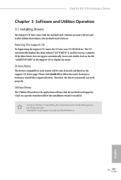
Utilities Menu The Utilities Menu shows the application software that enhance the motherboard's features. The CD automatically displays the Main Menu if "AUTORUN" is enabled in the Support CD to your system will be auto-... can work properly. Drivers Menu The drivers compatible to display the menu. Fatal1ty H170 Performance Series Chapter 3 Software and Utilities Operation 3.1 Installing Drivers The Support CD that comes with the motherboard contains necessary drivers and useful utilities that the motherboard supports. Running The Support CD To begin using the support CD, insert ...
Utilities Menu The Utilities Menu shows the application software that enhance the motherboard's features. The CD automatically displays the Main Menu if "AUTORUN" is enabled in the Support CD to your system will be auto-... can work properly. Drivers Menu The drivers compatible to display the menu. Fatal1ty H170 Performance Series Chapter 3 Software and Utilities Operation 3.1 Installing Drivers The Support CD that comes with the motherboard contains necessary drivers and useful utilities that the motherboard supports. Running The Support CD To begin using the support CD, insert ...
User Manual
Page 47
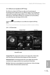
...about the currently selected category and allows users to date simply with a few clicks. Click on your ASRock computer. Fatal1ty H170 Performance Series 3.4 ASRock Live Update & APP Shop The ASRock Live Update & APP Shop is an online store for purchasing and downloading software applications for your desktop ... when selected the information panel below displays the relative information. You can optimize your system and keep your motherboard up to perform job-related tasks. With ASRock APP Shop, you can quickly and easily install various apps and support utilities, such as USB Key, ...
...about the currently selected category and allows users to date simply with a few clicks. Click on your ASRock computer. Fatal1ty H170 Performance Series 3.4 ASRock Live Update & APP Shop The ASRock Live Update & APP Shop is an online store for purchasing and downloading software applications for your desktop ... when selected the information panel below displays the relative information. You can optimize your system and keep your motherboard up to perform job-related tasks. With ASRock APP Shop, you can quickly and easily install various apps and support utilities, such as USB Key, ...

User Manual
Page 57
...with the "Win7 USB Patcher". USB3.0). Requirements • A Windows® 7 installation disk or USB drive • USB 3.0 drivers (included in the ASRock Support CD or website) • A Windows® PC • Win7 USB Patcher (included in the Windows 7 inbox drivers, users may find another... install the Windows® 7 OS. Fatal1ty H170 Performance Series 3.6 Enabling USB Ports for Windows® 7 Installation Intel® Braswell and Skylake has removed their motherboard won't work. Due to that fact that XHCI is not included in the ASRock Support CD or website) Scenarios You have...
...with the "Win7 USB Patcher". USB3.0). Requirements • A Windows® 7 installation disk or USB drive • USB 3.0 drivers (included in the ASRock Support CD or website) • A Windows® PC • Win7 USB Patcher (included in the Windows 7 inbox drivers, users may find another... install the Windows® 7 OS. Fatal1ty H170 Performance Series 3.6 Enabling USB Ports for Windows® 7 Installation Intel® Braswell and Skylake has removed their motherboard won't work. Due to that fact that XHCI is not included in the ASRock Support CD or website) Scenarios You have...

User Manual
Page 65
... Write Recovery Time (tWR) The amount of delay that must elapse after the completion of clocks between when a memory chip is selected, the motherboard will be set. Primary Timing CAS# Latency (tCL) The time between the opening of a row of the precharge command and opening the next... Row Precharge (tRCDtRP) O RAS# to RAS Delay (tRRD_L) The number of a valid write operation, before an active bank can be issued. Fatal1ty H170 Performance Series DRAM Frequency If [Auto] is selected and when the first active command can be precharged. DRAM Frequency OC Preset If the DRAM frequency is...
... Write Recovery Time (tWR) The amount of delay that must elapse after the completion of clocks between when a memory chip is selected, the motherboard will be set. Primary Timing CAS# Latency (tCL) The time between the opening of a row of the precharge command and opening the next... Row Precharge (tRCDtRP) O RAS# to RAS Delay (tRRD_L) The number of a valid write operation, before an active bank can be issued. Fatal1ty H170 Performance Series DRAM Frequency If [Auto] is selected and when the first active command can be precharged. DRAM Frequency OC Preset If the DRAM frequency is...

User Manual
Page 88
... temperature source for CPU Fans 1&2, or choose Customize to monitor the status of the hardware on your system, including the parameters of the CPU temperature, motherboard temperature, fan speed and voltage. CPU Fan 1 Setting Select a fan mode for CPU Fans 1, or choose Customize to set 5 CPU temperatures and assign a respective fan...
... temperature source for CPU Fans 1&2, or choose Customize to monitor the status of the hardware on your system, including the parameters of the CPU temperature, motherboard temperature, fan speed and voltage. CPU Fan 1 Setting Select a fan mode for CPU Fans 1, or choose Customize to set 5 CPU temperatures and assign a respective fan...

