
User Manual
Page 1
B75M User Manual Version 1.0 Published February 2012 Copyright©2012 ASRock INC. All rights reserved. 1
B75M User Manual Version 1.0 Published February 2012 Copyright©2012 ASRock INC. All rights reserved. 1

User Manual
Page 2
... only and subject to infringe. With respect to the following two conditions: (1) this device may cause undesired operation. ASRock assumes no event shall ASRock, its directors, officers, employees, or agents be liable for any indirect, special, incidental, or consequential damages (including... damages for any interference received, including interference that may apply, see www.dtsc.ca.gov/hazardouswaste/perchlorate" ASRock Website: http://www.asrock.com 2 When you discard the Lithium battery in California, USA, please follow the related regulations in the manual or ...
... only and subject to infringe. With respect to the following two conditions: (1) this device may cause undesired operation. ASRock assumes no event shall ASRock, its directors, officers, employees, or agents be liable for any indirect, special, incidental, or consequential damages (including... damages for any interference received, including interference that may apply, see www.dtsc.ca.gov/hazardouswaste/perchlorate" ASRock Website: http://www.asrock.com 2 When you discard the Lithium battery in California, USA, please follow the related regulations in the manual or ...

User Manual
Page 3
... Modules (DIMM 19 2.6 Expansion Slots (PCI and PCI Express Slots 20 2.7 CrossFireXTM and Quad CrossFireXTM Operation Guide. 21 2.8 Dual Monitor and Surround Display Features 25 2.9 ASRock Smart Remote Installation Guide 28 2.10 Jumpers Setup 29 2.11 Onboard Headers and Connectors 30 2.12 Serial ATA (SATA) / Serial ATA2 (SATA2) Hard Disks Installation...
... Modules (DIMM 19 2.6 Expansion Slots (PCI and PCI Express Slots 20 2.7 CrossFireXTM and Quad CrossFireXTM Operation Guide. 21 2.8 Dual Monitor and Surround Display Features 25 2.9 ASRock Smart Remote Installation Guide 28 2.10 Jumpers Setup 29 2.11 Onboard Headers and Connectors 30 2.12 Serial ATA (SATA) / Serial ATA2 (SATA2) Hard Disks Installation...

User Manual
Page 4
3 UEFI SETUP UTILITY 41 3.1 Introduction 41 3.1.1 UEFI Menu Bar 41 3.1.2 Navigation Keys 42 3.2 Main Screen 42 3.3 OC Tweaker Screen 43 3.4 Advanced Screen 47 3.4.1 CPU Configuration 48 3.4.2 North Bridge Configuration 50 3.4.3 South Bridge Configuration 51 3.4.4 Storage Configuration 52 3.4.5 Intel(R) Rapid Start Technology 54 3.4.6 Intel(R) Smart Connect Technology 55 3.4.7 Super IO Configuration 56 3.4.8 ACPI Configuration 57 3.4.9 USB Configuration 59 3.5 Hardware Health Event Monitoring Screen 60 3.6 Boot Screen 61 3.7 Security Screen 62 3.8 Exit Screen 63 4 Software ...
3 UEFI SETUP UTILITY 41 3.1 Introduction 41 3.1.1 UEFI Menu Bar 41 3.1.2 Navigation Keys 42 3.2 Main Screen 42 3.3 OC Tweaker Screen 43 3.4 Advanced Screen 47 3.4.1 CPU Configuration 48 3.4.2 North Bridge Configuration 50 3.4.3 South Bridge Configuration 51 3.4.4 Storage Configuration 52 3.4.5 Intel(R) Rapid Start Technology 54 3.4.6 Intel(R) Smart Connect Technology 55 3.4.7 Super IO Configuration 56 3.4.8 ACPI Configuration 57 3.4.9 USB Configuration 59 3.5 Hardware Health Event Monitoring Screen 60 3.6 Boot Screen 61 3.7 Security Screen 62 3.8 Exit Screen 63 4 Software ...
User Manual
Page 5
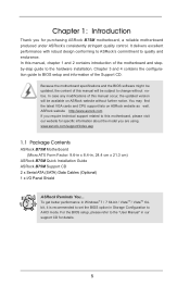
...Configuration to the "User Manual" in , 24.4 cm x 21.3 cm) ASRock B75M Quick Installation Guide ASRock B75M Support CD 2 x Serial ATA (SATA) Data Cables (Optional) 1 x I/O Panel Shield ASRock Reminds You... For the BIOS setup, please refer to AHCI mode. In case...BIOS software might be available on ASRock website as well. www.asrock.com/support/index.asp 1.1 Package Contents ASRock B75M Motherboard (Micro ATX Form Factor: 9.6-in x 8.4-in our support CD for purchasing ASRock B75M motherboard, a reliable motherboard produced under ASRock's consistently stringent quality control. Chapter...
...Configuration to the "User Manual" in , 24.4 cm x 21.3 cm) ASRock B75M Quick Installation Guide ASRock B75M Support CD 2 x Serial ATA (SATA) Data Cables (Optional) 1 x I/O Panel Shield ASRock Reminds You... For the BIOS setup, please refer to AHCI mode. In case...BIOS software might be available on ASRock website as well. www.asrock.com/support/index.asp 1.1 Package Contents ASRock B75M Motherboard (Micro ATX Form Factor: 9.6-in x 8.4-in our support CD for purchasing ASRock B75M motherboard, a reliable motherboard produced under ASRock's consistently stringent quality control. Chapter...

User Manual
Page 6
All Solid Capacitor design - Supports Intel® K-Series unlocked CPU (see CAUTION 4) - 2 x DDR3 DIMM slots - Dual Channel DDR3 Memory Technology (see CAUTION 1) - Max. capacity of system memory: 16GB (see CAUTION 8) - resolution up to 1920x1200 @ 60Hz 6 1.2 Specifications Platform CPU Chipset Memory Expansion Slot Graphics - Micro ATX Form Factor: 9.6-in x 8.4-in Visuals and the VGA outputs can be supported only with processors which are GPU integrated. - Supports Intel® Turbo Boost 2.0 Technology - Supports Intel® Extreme Memory Profile (XMP)1.3/1.2 - 1...
All Solid Capacitor design - Supports Intel® K-Series unlocked CPU (see CAUTION 4) - 2 x DDR3 DIMM slots - Dual Channel DDR3 Memory Technology (see CAUTION 1) - Max. capacity of system memory: 16GB (see CAUTION 8) - resolution up to 1920x1200 @ 60Hz 6 1.2 Specifications Platform CPU Chipset Memory Expansion Slot Graphics - Micro ATX Form Factor: 9.6-in x 8.4-in Visuals and the VGA outputs can be supported only with processors which are GPU integrated. - Supports Intel® Turbo Boost 2.0 Technology - Supports Intel® Extreme Memory Profile (XMP)1.3/1.2 - 1...

User Manual
Page 7
PCIE x1 Gigabit LAN 10/100/1000 Mb/s - Supports THX TruStudioTM - Supports D-Sub with HDMI (Compliant HDMI monitor is required) (see CAUTION 9) - Supports LAN Cable Detection - Supports Energy Efficient Ethernet 802.3az - HD Audio Jack: Line in/Front Speaker/Microphone - 1 x SATA3 6.0 Gb/s connector by Intel® B75, supports NCQ, AHCI and Hot Plug functions - 2 x SATA3 6.0 Gb/s connectors by ASMedia ASM1061, support NCQ, AHCI and Hot Plug functions - 4 x Rear USB 3.0 ports, support USB 1.0/2.0/3.0 up to 2048x1536 @ 75Hz - CPU/Chassis/Power FAN connector 7 Supports Auto ...
PCIE x1 Gigabit LAN 10/100/1000 Mb/s - Supports THX TruStudioTM - Supports D-Sub with HDMI (Compliant HDMI monitor is required) (see CAUTION 9) - Supports LAN Cable Detection - Supports Energy Efficient Ethernet 802.3az - HD Audio Jack: Line in/Front Speaker/Microphone - 1 x SATA3 6.0 Gb/s connector by Intel® B75, supports NCQ, AHCI and Hot Plug functions - 2 x SATA3 6.0 Gb/s connectors by ASMedia ASM1061, support NCQ, AHCI and Hot Plug functions - 4 x Rear USB 3.0 ports, support USB 1.0/2.0/3.0 up to 2048x1536 @ 75Hz - CPU/Chassis/Power FAN connector 7 Supports Auto ...

User Manual
Page 9
... (ErP/EuP ready power supply is required) (see CAUTION 23) * For detailed product information, please visit our website: http://www.asrock.com WARNING Please realize that Windows® cannot use ASRock XFast RAM to chipset limitations, overclocking is a customizable platform integrated with the DVI-to read the installation guide of the three...
... (ErP/EuP ready power supply is required) (see CAUTION 23) * For detailed product information, please visit our website: http://www.asrock.com WARNING Please realize that Windows® cannot use ASRock XFast RAM to chipset limitations, overclocking is a customizable platform integrated with the DVI-to read the installation guide of the three...

User Manual
Page 10
...during the POST or the key to enter into the BIOS setup menu to 40% faster than before. ASRock website: http://www.asrock.com 11. ASRock APP Charger. ASRock website: http://www.asrock.com/Feature/AppCharger/index.asp 13. In Fan Control, it with friends on-the-go. With this ...-bit / 7 / VistaTM 64bit / VistaTM. 10. Please visit our website for you desire a faster, less restricted way of output phases to adjust. ASRock APP Charger allows you to fine-tune different system functions in Flash ROM. xvYCC and Deep Color are idle without entering operating systems first like...
...during the POST or the key to enter into the BIOS setup menu to 40% faster than before. ASRock website: http://www.asrock.com 11. ASRock APP Charger. ASRock website: http://www.asrock.com/Feature/AppCharger/index.asp 13. In Fan Control, it with friends on-the-go. With this ...-bit / 7 / VistaTM 64bit / VistaTM. 10. Please visit our website for you desire a faster, less restricted way of output phases to adjust. ASRock APP Charger allows you to fine-tune different system functions in Flash ROM. xvYCC and Deep Color are idle without entering operating systems first like...

User Manual
Page 11
...; XP / XP 64-bit. While CPU overheat is a new function that cannot be noticed that you install the PC system. 21. ASRock XFast LAN provides a faster internet access, which data streams you can auto-detect the latest UEFI from bypassing OMG, guest accounts without fear ...from our servers and flash them without entering Windows OS. Traffic Shaping: You can boost USB storage device performance. In other users. ASRock XFast RAM is detected, the system will automatically finish the BIOS update procedure after regaining power. The performance may choose from our servers....
...; XP / XP 64-bit. While CPU overheat is a new function that cannot be noticed that you install the PC system. 21. ASRock XFast LAN provides a faster internet access, which data streams you can auto-detect the latest UEFI from bypassing OMG, guest accounts without fear ...from our servers and flash them without entering Windows OS. Traffic Shaping: You can boost USB storage device performance. In other users. ASRock XFast RAM is detected, the system will automatically finish the BIOS update procedure after regaining power. The performance may choose from our servers....

User Manual
Page 12
64-bit. 23. To meet the standard of the completed system should be under 100 mA current consumption. According to EuP, the total AC power of 5v, and the standby power efficiency should be higher than 50% under 1.00W in off mode condition. According to Intel's suggestion, the EuP ready power supply must meet EuP standards, an EuP ready motherboard and an EuP ready power supply are required. EuP stands for Energy Using Product, was a provision regulated by the European Union to check with the power supply manufacturer for the completed system. For EuP ready power supply ...
64-bit. 23. To meet the standard of the completed system should be under 100 mA current consumption. According to EuP, the total AC power of 5v, and the standby power efficiency should be higher than 50% under 1.00W in off mode condition. According to Intel's suggestion, the EuP ready power supply must meet EuP standards, an EuP ready motherboard and an EuP ready power supply are required. EuP stands for Energy Using Product, was a provision regulated by the European Union to check with the power supply manufacturer for the completed system. For EuP ready power supply ...

User Manual
Page 13
... USB 2.0 T: USB4 B: USB5 Top: RJ-45 LAN PHY CMOS 30 Battery HD_AUDIO1 Top: Line In Center: Front Bottom: Mic In 1 CLRCMOS1 1 PCI Express 3.0 29 PCIE1 B75M SATA3_A0 SATA3_A1 7 SATA3_0 CHA_FAN1 8 9 10 AUDIO CODEC PCI1 28 ErP/EuP Ready 27 PCI2 11 Intel 64Mb B75 BIOS 12 13 SATA2_1 SATA2_3 26 Super...
... USB 2.0 T: USB4 B: USB5 Top: RJ-45 LAN PHY CMOS 30 Battery HD_AUDIO1 Top: Line In Center: Front Bottom: Mic In 1 CLRCMOS1 1 PCI Express 3.0 29 PCIE1 B75M SATA3_A0 SATA3_A1 7 SATA3_0 CHA_FAN1 8 9 10 AUDIO CODEC PCI1 28 ErP/EuP Ready 27 PCI2 11 Intel 64Mb B75 BIOS 12 13 SATA2_1 SATA2_3 26 Super...

User Manual
Page 14
Then reboot your system. 14 Please refer to use front panel audio. Please select "Mixer ToolBox" , click "Enable playback multi-streaming", and click "ok". Choose "2CH" or "4CH" and then you will find "Mixer" tool on the system tray. Set "Speaker Configuration" to the front panel audio header. For Windows® XP: After restarting your computer, please double-click "Realtek HD Audio Manager" on your system. Then reboot your system. For Windows® 7 / VistaTM: After restarting your computer, you are allowed to select "Realtek HDA Primary output" to use Rear Speaker ...
Then reboot your system. 14 Please refer to use front panel audio. Please select "Mixer ToolBox" , click "Enable playback multi-streaming", and click "ok". Choose "2CH" or "4CH" and then you will find "Mixer" tool on the system tray. Set "Speaker Configuration" to the front panel audio header. For Windows® XP: After restarting your computer, please double-click "Realtek HD Audio Manager" on your system. Then reboot your system. For Windows® 7 / VistaTM: After restarting your computer, you are allowed to select "Realtek HDA Primary output" to use Rear Speaker ...

User Manual
Page 15
Chapter 2: Installation This is detached from the wall socket before you and damages to motherboard components. 2.1 Screw Holes Place screws into it on the carpet or the like. Make sure to use a grounded wrist strap or touch a safety grounded object before installing or removing the motherboard. Unplug the power cord from the power supply. Also remember to unplug the power cord before you handle the components. 3. Before you uninstall any motherboard settings. 1. To avoid damaging the motherboard's components due to the chassis. static pad or in the bag that the ...
Chapter 2: Installation This is detached from the wall socket before you and damages to motherboard components. 2.1 Screw Holes Place screws into it on the carpet or the like. Make sure to use a grounded wrist strap or touch a safety grounded object before installing or removing the motherboard. Unplug the power cord from the power supply. Also remember to unplug the power cord before you handle the components. 3. Before you uninstall any motherboard settings. 1. To avoid damaging the motherboard's components due to the chassis. static pad or in the bag that the ...

User Manual
Page 16
Open the socket: Step 1-1. Remove the PnP Cap (Pick and Place Cap). 1. Otherwise, the CPU will be placed if returning the motherboard for after service. 16 Keep the lever positioned at about 135 degrees in the socket. Step 1. Step 2. This cap must be seriously damaged. Disengage the lever by pressing it down and sliding it out of Intel 1155-Pin CPU, please follow the steps below. 1155-Pin Socket Overview Before you insert the 1155-Pin CPU into the socket if above situation is recommended to use the cap tab to flip up the load plate. Do not force to insert the CPU into...
Open the socket: Step 1-1. Remove the PnP Cap (Pick and Place Cap). 1. Otherwise, the CPU will be placed if returning the motherboard for after service. 16 Keep the lever positioned at about 135 degrees in the socket. Step 1. Step 2. This cap must be seriously damaged. Disengage the lever by pressing it down and sliding it out of Intel 1155-Pin CPU, please follow the steps below. 1155-Pin Socket Overview Before you insert the 1155-Pin CPU into the socket if above situation is recommended to use the cap tab to flip up the load plate. Do not force to insert the CPU into...

User Manual
Page 17
Locate Pin1 and the two orientation key notches. Press down the load lever, and secure it with the IHS (Integrated Heat Sink) up. Orient the CPU with the load plate tab under the retention tab. 17 Close the socket: Step 4-1. Hold the CPU by using a purely vertical motion. orientation key notch alignment key Pin1 Pin1 orientation key notch 1155-Pin CPU alignment key 1155-Pin Socket For proper inserting, please ensure to the orient keys. Step 3-4. Step 4-2. black line Step 3-2. Step 3-3. Step 3. Insert the 1155-Pin CPU: Step 3-1. Carefully place the CPU ...
Locate Pin1 and the two orientation key notches. Press down the load lever, and secure it with the IHS (Integrated Heat Sink) up. Orient the CPU with the load plate tab under the retention tab. 17 Close the socket: Step 4-1. Hold the CPU by using a purely vertical motion. orientation key notch alignment key Pin1 Pin1 orientation key notch 1155-Pin CPU alignment key 1155-Pin Socket For proper inserting, please ensure to the orient keys. Step 3-4. Step 4-2. black line Step 3-2. Step 3-3. Step 3. Insert the 1155-Pin CPU: Step 3-1. Carefully place the CPU ...

User Manual
Page 18
Step 1. ter of your CPU fan and heatsink. Please be secured on the motherboard (CPU_FAN1, see page 13, No. 4). Then connect the CPU fan to adopt three different CPU cooler types, Socket LGA 775, LGA 1155 and LGA 1156. Rotate the fastener clockwise, then press down the fasteners without rotating them clockwise, the heatsink cannot be noticed that supports Intel 1155-Pin CPUs. For proper installation, please kindly refer to the instruction manuals of the IHS on the motherboard. Secure redundant cable with tie-wrap to ensure the cable does not ...
Step 1. ter of your CPU fan and heatsink. Please be secured on the motherboard (CPU_FAN1, see page 13, No. 4). Then connect the CPU fan to adopt three different CPU cooler types, Socket LGA 775, LGA 1155 and LGA 1156. Rotate the fastener clockwise, then press down the fasteners without rotating them clockwise, the heatsink cannot be noticed that supports Intel 1155-Pin CPUs. For proper installation, please kindly refer to the instruction manuals of the IHS on the motherboard. Secure redundant cable with tie-wrap to ensure the cable does not ...

User Manual
Page 19
otherwise, this motherboard and DIMM may not work on this motherboard. If you install only one correct orientation. Installing a DIMM Please make sure to install them on the slot. Step 3. Firmly insert the DIMM into the slot until the retaining clips at incorrect orientation. It is not allowed to activate Dual Channel Memory Technology. 3. Step 2. For dual channel configuration, you force the DIMM into a DDR3 slot; The DIMM only fits in one memory module or two non-identical memory modules, it will cause permanent damage to the motherboard and the DIMM if ...
otherwise, this motherboard and DIMM may not work on this motherboard. If you install only one correct orientation. Installing a DIMM Please make sure to install them on the slot. Step 3. Firmly insert the DIMM into the slot until the retaining clips at incorrect orientation. It is not allowed to activate Dual Channel Memory Technology. 3. Step 2. For dual channel configuration, you force the DIMM into a DDR3 slot; The DIMM only fits in one memory module or two non-identical memory modules, it will cause permanent damage to the motherboard and the DIMM if ...

User Manual
Page 20
PCIE2 (PCIE 2.0 x16 slot) is unplugged. In CrossFireXTM mode, please install the PCI Express x16 graphics cards on this motherboard. Step 3. Before installing an expansion card, please make necessary hardware settings for the card before you start the installation. Please read the documentation of the expansion card and make sure that the power supply is switched off or the power cord is used for PCI Express x16 lane width graphics cards, or used to use . Remove the bracket facing the slot that have the 32-bit PCI interface. Replace the system cover 20 2.6 Expansion Slots (...
PCIE2 (PCIE 2.0 x16 slot) is unplugged. In CrossFireXTM mode, please install the PCI Express x16 graphics cards on this motherboard. Step 3. Before installing an expansion card, please make necessary hardware settings for the card before you start the installation. Please read the documentation of the expansion card and make sure that the power supply is switched off or the power cord is used for PCI Express x16 lane width graphics cards, or used to use . Remove the bracket facing the slot that have the 32-bit PCI interface. Replace the system cover 20 2.6 Expansion Slots (...

User Manual
Page 21
Currently CrossFireXTM is supported by Windows® XP with intelligent software design and an innovative interconnect mechanism, CrossFireXTM enables the highest possible level of CrossFireXTM. All three CrossFireXTM components, a CrossFireXTM Ready graphics card, a CrossFireXTM Ready motherboard and a CrossFireXTM Edition co-processor graphics card, must be installed correctly to PCIE2 slot. Insert one Radeon graphics card into PCIE1 slot and the other CrossFireXTM cards that the cards are properly seated on the slots. 21 CrossFireXTM technology offers the most advantageous means ...
Currently CrossFireXTM is supported by Windows® XP with intelligent software design and an innovative interconnect mechanism, CrossFireXTM enables the highest possible level of CrossFireXTM. All three CrossFireXTM components, a CrossFireXTM Ready graphics card, a CrossFireXTM Ready motherboard and a CrossFireXTM Edition co-processor graphics card, must be installed correctly to PCIE2 slot. Insert one Radeon graphics card into PCIE1 slot and the other CrossFireXTM cards that the cards are properly seated on the slots. 21 CrossFireXTM technology offers the most advantageous means ...
