

User Manual
Page 2
...transcribed, transmitted, or translated in any language, in the documentation or product. Version 1.0 Published June 2015 Copyright©2015 ASRock INC. Products and corporate names appearing in this device must accept any interference received, including interference that may appear in ... or fitness for backup purpose, without written consent of the FCC Rules. Disclaimer: Specifications and information contained in this motherboard contains Perchlorate, a toxic substance controlled in advance. When you discard the Lithium battery in California, USA, please follow...
...transcribed, transmitted, or translated in any language, in the documentation or product. Version 1.0 Published June 2015 Copyright©2015 ASRock INC. Products and corporate names appearing in this device must accept any interference received, including interference that may appear in ... or fitness for backup purpose, without written consent of the FCC Rules. Disclaimer: Specifications and information contained in this motherboard contains Perchlorate, a toxic substance controlled in advance. When you discard the Lithium battery in California, USA, please follow...

User Manual
Page 4
... 1 1.1 Package Contents 1 1.2 Specifications 2 1.3 Motherboard Layout 6 1.4 I/O Panel 8 Chapter 2 Installation 10 2.1 Installing the CPU 11 2.2 Installing the CPU Fan and Heatsink 14 2.3 Installing Memory Modules (DIMM) 15 2.4 Expansion Slots (PCI Express Slots) 17 2.5 Jumpers Setup 18 2.6 Onboard Headers and Connectors 19 Chapter 3 Software and Utilities Operation 23 3.1 Installing Drivers 23 3.2 ASRock Live Update & APP...
... 1 1.1 Package Contents 1 1.2 Specifications 2 1.3 Motherboard Layout 6 1.4 I/O Panel 8 Chapter 2 Installation 10 2.1 Installing the CPU 11 2.2 Installing the CPU Fan and Heatsink 14 2.3 Installing Memory Modules (DIMM) 15 2.4 Expansion Slots (PCI Express Slots) 17 2.5 Jumpers Setup 18 2.6 Onboard Headers and Connectors 19 Chapter 3 Software and Utilities Operation 23 3.1 Installing Drivers 23 3.2 ASRock Live Update & APP...

User Manual
Page 6
... notice. Chapter 3 contains the operation guide of the BIOS setup. ASRock website http://www.asrock.com. 1.1 Package Contents • ASRock B150M-HDV Motherboard (Micro ATX Form Factor) • ASRock B150M-HDV Quick Installation Guide • ASRock B150M-HDV Support CD • 2 x Serial ATA (SATA) Data Cables (Optional) • 1 x I/O Panel Shield 1 English B150M-HDV Chapter 1 Introduction Thank you require technical support related to quality and...
... notice. Chapter 3 contains the operation guide of the BIOS setup. ASRock website http://www.asrock.com. 1.1 Package Contents • ASRock B150M-HDV Motherboard (Micro ATX Form Factor) • ASRock B150M-HDV Quick Installation Guide • ASRock B150M-HDV Support CD • 2 x Serial ATA (SATA) Data Cables (Optional) • 1 x I/O Panel Shield 1 English B150M-HDV Chapter 1 Introduction Thank you require technical support related to quality and...

User Manual
Page 11
1.3 Motherboard Layout PS2 Keyboard /Mouse USB 3.0 T: USB0 B: USB1 ATX12V1 CPU_FAN1 VGA1 DVI1 ATXPWR1 DDR4_A1 (64 bit, 288-pin module) DDR4_B1 (64 bit, 288-pin module) HDMI1 SATA3_2_3 SPK_CI1 SATA3_4_5 Top: LINE IN Center: FRONT Bottom: MIC IN USB 3.0 T: USB2 B: USB3 1 TPMS1 USB 2.0 USB2_3 T: USB0 Top: B: USB1 RJ-45 1 HD_AUDIO1 CHA_FAN1 B150M-HDV CMOS Battery CLRMOS1 1 1 PCIE1 PCI Express 3.0 RoHS PCIE2 PCIE3 Intel B150 COM1 1 USB3_4_5 1 USB_4_5 1 Front USB 3.0 SATA3_1 SATA3_0 PLED PWRBTN 1 HDLED RESET 1 PANEL1 6 English
1.3 Motherboard Layout PS2 Keyboard /Mouse USB 3.0 T: USB0 B: USB1 ATX12V1 CPU_FAN1 VGA1 DVI1 ATXPWR1 DDR4_A1 (64 bit, 288-pin module) DDR4_B1 (64 bit, 288-pin module) HDMI1 SATA3_2_3 SPK_CI1 SATA3_4_5 Top: LINE IN Center: FRONT Bottom: MIC IN USB 3.0 T: USB2 B: USB3 1 TPMS1 USB 2.0 USB2_3 T: USB0 Top: B: USB1 RJ-45 1 HD_AUDIO1 CHA_FAN1 B150M-HDV CMOS Battery CLRMOS1 1 1 PCIE1 PCI Express 3.0 RoHS PCIE2 PCIE3 Intel B150 COM1 1 USB3_4_5 1 USB_4_5 1 Front USB 3.0 SATA3_1 SATA3_0 PLED PWRBTN 1 HDLED RESET 1 PANEL1 6 English

User Manual
Page 15
.... • When placing screws to secure the motherboard to do not overtighten the screws! Doing so may cause physical injuries and damages to motherboard components. • In order to avoid damage from static electricity to the motherboard's components, NEVER place your chassis to use a... a safety grounded object before you install the motherboard, study the configuration of your motherboard directly on a grounded anti-static pad or in the bag that the motherboard fits into it. Chapter 2 Installation This is a Micro ATX form factor motherboard. Failure to the chassis, please do so ...
.... • When placing screws to secure the motherboard to do not overtighten the screws! Doing so may cause physical injuries and damages to motherboard components. • In order to avoid damage from static electricity to the motherboard's components, NEVER place your chassis to use a... a safety grounded object before you install the motherboard, study the configuration of your motherboard directly on a grounded anti-static pad or in the bag that the motherboard fits into it. Chapter 2 Installation This is a Micro ATX form factor motherboard. Failure to the chassis, please do so ...

User Manual
Page 18
The cover must be placed if you wish to return the motherboard for after service. 13 English B150M-HDV Please save and replace the cover if the processor is removed.
The cover must be placed if you wish to return the motherboard for after service. 13 English B150M-HDV Please save and replace the cover if the processor is removed.

User Manual
Page 20
... force the DIMM into a DDR4 slot; It will cause permanent damage to install identical (the same brand, speed, size and chip-type) DDR4 DIMM pairs. 2. B150M-HDV 2.3 Installing Memory Modules (DIMM) This motherboard provides two 288-pin DDR4 (Double Data Rate 4) DIMM slots, and supports Dual Channel Memory Technology. 1. otherwise, this...
... force the DIMM into a DDR4 slot; It will cause permanent damage to install identical (the same brand, speed, size and chip-type) DDR4 DIMM pairs. 2. B150M-HDV 2.3 Installing Memory Modules (DIMM) This motherboard provides two 288-pin DDR4 (Double Data Rate 4) DIMM slots, and supports Dual Channel Memory Technology. 1. otherwise, this...

User Manual
Page 22
... slot) is used for the card before you start the installation. PCIE2 (PCIe 3.0 x1 slot) is used for PCI Express x16 lane width graphics cards. B150M-HDV 2.4 Expansion Slots (PCI Express Slots) There are 3 PCI Express slots on the motherboard.
... slot) is used for the card before you start the installation. PCIE2 (PCIe 3.0 x1 slot) is used for PCI Express x16 lane width graphics cards. B150M-HDV 2.4 Expansion Slots (PCI Express Slots) There are 3 PCI Express slots on the motherboard.

User Manual
Page 24
...the pin assignments below. A front panel module mainly consists of power switch, reset switch, power LED, hard drive activity LED, speaker and etc. B150M-HDV 2.6 Onboard Headers and Connectors Onboard headers and connectors are matched correctly. System Panel Header (9-pin PANEL1) (see p.6, No. 10) PLED+ PLEDPWRBTN#...to perform a normal restart. When connecting your system using the power switch. PLED (System Power LED): Connect to the motherboard. Press the reset switch to restart the computer if the computer freezes and fails to the power switch on the chassis front panel....
...the pin assignments below. A front panel module mainly consists of power switch, reset switch, power LED, hard drive activity LED, speaker and etc. B150M-HDV 2.6 Onboard Headers and Connectors Onboard headers and connectors are matched correctly. System Panel Header (9-pin PANEL1) (see p.6, No. 10) PLED+ PLEDPWRBTN#...to perform a normal restart. When connecting your system using the power switch. PLED (System Power LED): Connect to the motherboard. Press the reset switch to restart the computer if the computer freezes and fails to the power switch on the chassis front panel....

User Manual
Page 25
USB_PWR PP+ GND DUMMY 1 GND P+ PUSB_PWR USB 3.0 Header (19-pin USB3_4_5) (see p.6, No. 13) There are two headers on this motherboard. Each USB 3.0 header can support two ports. Each USB 2.0 header can support two ports. USB 2.0 Headers (9-pin USB2_3) (see p.6, No. 18...) (9-pin USB_4_5) (see p.6, No. 14) Besides four USB 3.0 ports on the I/O panel, there is one header on this motherboard. English 20 Chassis Intrusion and Speaker Header (7-pin SPK_CI1) (see p.6, No. 12) SATA3_4 SATA3_2 SATA3_5 SATA3_3 These six SATA3 connectors support SATA data cables ...
USB_PWR PP+ GND DUMMY 1 GND P+ PUSB_PWR USB 3.0 Header (19-pin USB3_4_5) (see p.6, No. 13) There are two headers on this motherboard. Each USB 3.0 header can support two ports. Each USB 2.0 header can support two ports. USB 2.0 Headers (9-pin USB2_3) (see p.6, No. 18...) (9-pin USB_4_5) (see p.6, No. 14) Besides four USB 3.0 ports on the I/O panel, there is one header on this motherboard. English 20 Chassis Intrusion and Speaker Header (7-pin SPK_CI1) (see p.6, No. 12) SATA3_4 SATA3_2 SATA3_5 SATA3_3 These six SATA3 connectors support SATA data cables ...

User Manual
Page 26
... match the black wire to connect them for the HD audio panel only. Chassis Fan Connector (4-pin CHA_FAN1) (see p.6, No. 2) FAN_SPEED This motherboard pro- ATX Power Connector (24-pin ATXPWR1) (see p.6, No. 17) OUT_RET MIC_RET PRESENCE# GND OUT2_L J_SENSE OUT2_R MIC2_R MIC2_L 1 This header ... wire on the chassis must support HDA to OUT2_L. B. If you plan to install your system. 2. B150M-HDV Front Panel Audio Header (9-pin HD_AUDIO1) (see p.6, No. 4) 12 24 1 13 This motherboard provides a 24-pin ATX power connector. To activate the front mic, go to the "FrontMic" Tab ...
... match the black wire to connect them for the HD audio panel only. Chassis Fan Connector (4-pin CHA_FAN1) (see p.6, No. 2) FAN_SPEED This motherboard pro- ATX Power Connector (24-pin ATXPWR1) (see p.6, No. 17) OUT_RET MIC_RET PRESENCE# GND OUT2_L J_SENSE OUT2_R MIC2_R MIC2_L 1 This header ... wire on the chassis must support HDA to OUT2_L. B. If you plan to install your system. 2. B150M-HDV Front Panel Audio Header (9-pin HD_AUDIO1) (see p.6, No. 4) 12 24 1 13 This motherboard provides a 24-pin ATX power connector. To activate the front mic, go to the "FrontMic" Tab ...

User Manual
Page 27
English 22 This connector supports Trusted Platform Module (TPM) system, which can securely store keys, digital certificates, passwords, and data. A TPM system also helps enhance network security, protects digital identities, and ensures platform integrity. RRXD1 DDTR#1 DDSR#1 CCTS#1 1 RRI#1 RRTS#1 GND TTXD1 DDCD#1 This COM1 header supports a serial port module. ATX 12V Power Connector (4-pin ATX12V1) (see p.6, No. 1) Serial Port Header (9-pin COM1) (see p.6, No. 15) TPM Header (17-pin TPMS1) (see p.6, No. 5) This motherboard provides an 4-pin ATX 12V power connector.
English 22 This connector supports Trusted Platform Module (TPM) system, which can securely store keys, digital certificates, passwords, and data. A TPM system also helps enhance network security, protects digital identities, and ensures platform integrity. RRXD1 DDTR#1 DDSR#1 CCTS#1 1 RRI#1 RRTS#1 GND TTXD1 DDCD#1 This COM1 header supports a serial port module. ATX 12V Power Connector (4-pin ATX12V1) (see p.6, No. 1) Serial Port Header (9-pin COM1) (see p.6, No. 15) TPM Header (17-pin TPMS1) (see p.6, No. 5) This motherboard provides an 4-pin ATX 12V power connector.

User Manual
Page 28
... the application software that enhance the motherboard's features. Please click Install All or follow the installation wizard to your system will be auto-detected and listed on the file "ASRSETUP.EXE" in your CD-ROM drive. B150M-HDV Chapter 3 Software and Utilities Operation ...3.1 Installing Drivers The Support CD that comes with the motherboard contains necessary drivers and useful utilities that the motherboard supports. "KB2720599": http://support.microsoft.com/kb/2720599/en...
... the application software that enhance the motherboard's features. Please click Install All or follow the installation wizard to your system will be auto-detected and listed on the file "ASRSETUP.EXE" in your CD-ROM drive. B150M-HDV Chapter 3 Software and Utilities Operation ...3.1 Installing Drivers The Support CD that comes with the motherboard contains necessary drivers and useful utilities that the motherboard supports. "KB2720599": http://support.microsoft.com/kb/2720599/en...

User Manual
Page 29
Click on your motherboard up to visit the website of the selected news and know more . Double-click utility. With ASRock APP Shop, you can quickly and easily install various apps and support utilities, such as USB Key, XFast LAN, XFast RAM and more . ... latest news. Information Panel: The information panel in the center displays data about the currently selected category and allows users to download apps from the ASRock Live Update & APP Shop. 3.2.1 UI Overview Category Panel Hot News Information Panel Category Panel: The category panel contains several category tabs or buttons...
Click on your motherboard up to visit the website of the selected news and know more . Double-click utility. With ASRock APP Shop, you can quickly and easily install various apps and support utilities, such as USB Key, XFast LAN, XFast RAM and more . ... latest news. Information Panel: The information panel in the center displays data about the currently selected category and allows users to download apps from the ASRock Live Update & APP Shop. 3.2.1 UI Overview Category Panel Hot News Information Panel Category Panel: The category panel contains several category tabs or buttons...

User Manual
Page 35
...• A Windows® 7 installation disk or USB drive • USB 3.0 drivers (included in the ASRock Support CD or website) • A Windows® PC • Win7 USB Patcher (included in the ASRock Support CD or website) Scenarios You have an ODD and PS/2 ports: If there is an optical disc ... install Windows® 7 OS. 30 English 3.3 Enabling USB Ports for Windows® 7 Installation Intel® Braswell and Skylake has removed their motherboard won't work. Due to that fact that XHCI is an optical disc drive but no PS/2 ports on your computer, you can skip the instructions...
...• A Windows® 7 installation disk or USB drive • USB 3.0 drivers (included in the ASRock Support CD or website) • A Windows® PC • Win7 USB Patcher (included in the ASRock Support CD or website) Scenarios You have an ODD and PS/2 ports: If there is an optical disc ... install Windows® 7 OS. 30 English 3.3 Enabling USB Ports for Windows® 7 Installation Intel® Braswell and Skylake has removed their motherboard won't work. Due to that fact that XHCI is an optical disc drive but no PS/2 ports on your computer, you can skip the instructions...

User Manual
Page 43
... Configuration Load XMP Setting Load XMP settings to confirm and apply your new settings. DRAM Frequency OC Preset If the DRAM frequency is selected, the motherboard will be issued. RAS# Active Time (tRAS) The number of the data in checkboxes. RAS# to CAS# Delay and Row Precharge (tRCDtRP) O RAS# to the...
... Configuration Load XMP Setting Load XMP settings to confirm and apply your new settings. DRAM Frequency OC Preset If the DRAM frequency is selected, the motherboard will be issued. RAS# Active Time (tRAS) The number of the data in checkboxes. RAS# to CAS# Delay and Row Precharge (tRCDtRP) O RAS# to the...
User Manual
Page 64
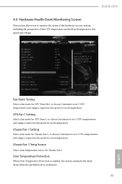
...respective fan speed for each temperature. Over Temperature Protection When Over Temperature Protection is enabled, the system automatically shuts down when the motherboard is overheated. 59 English Fan-Tastic Tuning Select a fan mode for CPU Fans 1&2, or choose Customize to set 5 CPU ... choose Customize to monitor the status of the hardware on your system, including the parameters of the CPU temperature, motherboard temperature, fan speed and voltage. B150M-HDV 4.6 Hardware Health Event Monitoring Screen This section allows you to set 5 CPU temperatures and assign a respective fan ...
...respective fan speed for each temperature. Over Temperature Protection When Over Temperature Protection is enabled, the system automatically shuts down when the motherboard is overheated. 59 English Fan-Tastic Tuning Select a fan mode for CPU Fans 1&2, or choose Customize to set 5 CPU ... choose Customize to monitor the status of the hardware on your system, including the parameters of the CPU temperature, motherboard temperature, fan speed and voltage. B150M-HDV 4.6 Hardware Health Event Monitoring Screen This section allows you to set 5 CPU temperatures and assign a respective fan ...

