RAID Installation Guide
Page 1
... ... 5 1.3.1 Installing Windows XP / XP 64-bit With RAID Funtions 5 1.3.2 Installing Windows 7 / 7 64-bit / Vista / Vista 64-bit With RAID Funtions 6 1.4 Opening Option ROM 7 1.5 Using the Main Menu 8 1.6 Viewing Drive Assignments 9 1.7 Secure Erasing a Physical Drive 10 1.8 Creating a Logical Drive 12 1.9 Deleting a Logical Drive 17 1.10 Viewing Controller Configuration 18 1.11 Responding to...
... ... 5 1.3.1 Installing Windows XP / XP 64-bit With RAID Funtions 5 1.3.2 Installing Windows 7 / 7 64-bit / Vista / Vista 64-bit With RAID Funtions 6 1.4 Opening Option ROM 7 1.5 Using the Main Menu 8 1.6 Viewing Drive Assignments 9 1.7 Secure Erasing a Physical Drive 10 1.8 Creating a Logical Drive 12 1.9 Deleting a Logical Drive 17 1.10 Viewing Controller Configuration 18 1.11 Responding to...

RAID Installation Guide
Page 8
Press 3 to view the controller configuration. Press Esc (Escape) to exit the utility and reboot your computer screen, press Ctrl-F to create a logical drive or view information about an existing logical drive. 1.5 Using the Main Menu When the Option ROM displays on your PC. 8 Press 4 to delete a logical drive. The Main Menu (above) has five options: Press 1 to view physical drive assignments Press 2 to enter the Utility and display the Main Menu.
Press 3 to view the controller configuration. Press Esc (Escape) to exit the utility and reboot your computer screen, press Ctrl-F to create a logical drive or view information about an existing logical drive. 1.5 Using the Main Menu When the Option ROM displays on your PC. 8 Press 4 to delete a logical drive. The Main Menu (above) has five options: Press 1 to view physical drive assignments Press 2 to enter the Utility and display the Main Menu.

RAID Installation Guide
Page 9
..., such as SATA 1.5 Gb/s, 3.0 Gb/s, or 6.0 Gb/s. This screen reports physical drive assignments and provides the following information: Port: ID - 1.6 Viewing Drive Assignments From the Main Menu screen, press 1 to create a new logical drive.
..., such as SATA 1.5 Gb/s, 3.0 Gb/s, or 6.0 Gb/s. This screen reports physical drive assignments and provides the following information: Port: ID - 1.6 Viewing Drive Assignments From the Main Menu screen, press 1 to create a new logical drive.

RAID Installation Guide
Page 10
... erase a physical drive that belongs to go Critical or Offline. Back up any important data before you want . To secure erase a physical drive: 1 From the Main Menu screen, press 1 to see the View Drive Assignments screen. 2 Press the arrow keys to restore your data after a secure erase. The caution screen appears...
... erase a physical drive that belongs to go Critical or Offline. Back up any important data before you want . To secure erase a physical drive: 1 From the Main Menu screen, press 1 to see the View Drive Assignments screen. 2 Press the arrow keys to restore your data after a secure erase. The caution screen appears...

RAID Installation Guide
Page 12
... Define LD Menu appears for the number you selected. ٛ Initialization. Press the arrow keys to move to select it. 1.8 Creating a Logical Drive 1 From the Main Menu screen, press 2 to toggle between ON and OFF. ٛ Read Policy. Press the Spacebar to display the Define LD Menu. 2.
... Define LD Menu appears for the number you selected. ٛ Initialization. Press the arrow keys to move to select it. 1.8 Creating a Logical Drive 1 From the Main Menu screen, press 2 to toggle between ON and OFF. ٛ Read Policy. Press the Spacebar to display the Define LD Menu. 2.

RAID Installation Guide
Page 14
... from Create Logical Drive step 8, above. 1 Press Ctrl-Y to allocate a portion of the logical drive for one logical drive. 2 Press Esc to exit to the Main Menu. Press Esc again to exit the Utility. 3 Press Y to select an available logical drive number and press Enter. 14 You have successfully created a new...
... from Create Logical Drive step 8, above. 1 Press Ctrl-Y to allocate a portion of the logical drive for one logical drive. 2 Press Esc to exit to the Main Menu. Press Esc again to exit the Utility. 3 Press Y to select an available logical drive number and press Enter. 14 You have successfully created a new...

RAID Installation Guide
Page 15
...Assignment, the physical drives are split between two logical drives. and LD 1-2 means logical drive 1, physical drive 2. 15 Extent 2 belongs to the Main Menu. Choose the RAID level and options for the second logical drive. The physical drives on Ports 1 and 2 reflect smaller capacities because a portion ...Drive Assignments, Split Physical Drives After you can use it. In this example, observe how each of physical drives, press 1 on the Main Menu screen to the first logical drive. Note You must be partition and format your logical drive configuration. 6 Press Esc to exit to ...
...Assignment, the physical drives are split between two logical drives. and LD 1-2 means logical drive 1, physical drive 2. 15 Extent 2 belongs to the Main Menu. Choose the RAID level and options for the second logical drive. The physical drives on Ports 1 and 2 reflect smaller capacities because a portion ...Drive Assignments, Split Physical Drives After you can use it. In this example, observe how each of physical drives, press 1 on the Main Menu screen to the first logical drive. Note You must be partition and format your logical drive configuration. 6 Press Esc to exit to ...

RAID Installation Guide
Page 17
... drive appears. 3 Press Ctrl-Y to the Delete LD Menu. The screen returns to confirm and complete logical drive deletion. To delete a logical drive: 1 From the Main Menu screen, press 3 to display the Delete LD Menu. 2 Highlight the logical drive you wish to back up any important data before you delete a logical... Drive Warning When you delete a logical drive, you delete all data on it, you cannot delete that logical drive. Press Esc to return to the Main Menu. 17
... drive appears. 3 Press Ctrl-Y to the Delete LD Menu. The screen returns to confirm and complete logical drive deletion. To delete a logical drive: 1 From the Main Menu screen, press 3 to display the Delete LD Menu. 2 Highlight the logical drive you wish to back up any important data before you delete a logical... Drive Warning When you delete a logical drive, you delete all data on it, you cannot delete that logical drive. Press Esc to return to the Main Menu. 17

RAID Installation Guide
Page 18
The Controller Configuration Options screen provides diagnostic information that might be helpful for troubleshooting purposes: The system IRQ used by the RAID controller Base Address 18 1.10 Viewing Controller Configuration From the Main Menu screen, press 4 to display the Controller Configuration Options screen.
The Controller Configuration Options screen provides diagnostic information that might be helpful for troubleshooting purposes: The system IRQ used by the RAID controller Base Address 18 1.10 Viewing Controller Configuration From the Main Menu screen, press 4 to display the Controller Configuration Options screen.

User Manual
Page 4
... Support CD 53 4.2.2 Drivers Menu 53 4.2.3 Utilities Menu 53 4.2.4 Contact Information 53 4 3. UEFI SETUP UTILITY 35 3.1 Introduction 35 3.1.1 UEFI Menu Bar 35 3.1.2 Navigation Keys 36 3.2 Main Screen 36 3.3 OC Tweaker Screen 37 3.4 Advanced Screen 40 3.4.1 CPU Configuration 41 3.4.2 North Bridge Configuration 42 3.4.3 South Bridge Configuration...
... Support CD 53 4.2.2 Drivers Menu 53 4.2.3 Utilities Menu 53 4.2.4 Contact Information 53 4 3. UEFI SETUP UTILITY 35 3.1 Introduction 35 3.1.1 UEFI Menu Bar 35 3.1.2 Navigation Keys 36 3.2 Main Screen 36 3.3 OC Tweaker Screen 37 3.4 Advanced Screen 40 3.4.1 CPU Configuration 41 3.4.2 North Bridge Configuration 42 3.4.3 South Bridge Configuration...

User Manual
Page 20
... select the "Display Settings" tab so that you can adjust the parameters of the multi-monitor according to three. Click the items "This is my main monitor" and "Extend the desktop onto this monitor". Click "OK" to save your monitors that you would like to another. 20 Right-click the display...
... select the "Display Settings" tab so that you can adjust the parameters of the multi-monitor according to three. Click the items "This is my main monitor" and "Extend the desktop onto this monitor". Click "OK" to save your monitors that you would like to another. 20 Right-click the display...

User Manual
Page 26
... reset switch on the chassis front panel. PWRBTN (Power Switch): Connect to the hard drive activity LED on the chassis front panel. A front panel module mainly consists of power switch, reset switch, power LED, hard drive activity LED, speaker and etc. CPU Fan Connectors (4-pin CPU_FAN1) (see p.11 No. 9) 1 SPEAKER DUMMY...
... reset switch on the chassis front panel. PWRBTN (Power Switch): Connect to the hard drive activity LED on the chassis front panel. A front panel module mainly consists of power switch, reset switch, power LED, hard drive activity LED, speaker and etc. CPU Fan Connectors (4-pin CPU_FAN1) (see p.11 No. 9) 1 SPEAKER DUMMY...

User Manual
Page 35
... how to use the mouse to choose among the selections on the system chassis. Because the UEFI software is constantly being updated, the following selections: Main To set up the system time/date information OC Tweaker To set up overclocking features Advanced To set up the advanced UEFI features H/W Monitor To...
... how to use the mouse to choose among the selections on the system chassis. Because the UEFI software is constantly being updated, the following selections: Main To set up the system time/date information OC Tweaker To set up overclocking features Advanced To set up the advanced UEFI features H/W Monitor To...

User Manual
Page 36
... settings Save changes and exit the UEFI SETUP UTILITY Print screen Jump to the Exit Screen or exit the current screen 3.2 Main Screen When you enter the UEFI SETUP UTILITY, the Main screen will appear and display the system overview. 36 Navigation Key(s) Function Description / Moves cursor left or right to select...
... settings Save changes and exit the UEFI SETUP UTILITY Print screen Jump to the Exit Screen or exit the current screen 3.2 Main Screen When you enter the UEFI SETUP UTILITY, the Main screen will appear and display the system overview. 36 Navigation Key(s) Function Description / Moves cursor left or right to select...
User Manual
Page 53
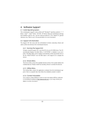
... detects the installed devices. Refer to your OS documentation for more about ASRock, welcome to install it. 4.2.4 Contact Information If you may contact your dealer for general reference only. If the Main Menu did not appear automatically, locate and double click on a specifi...;c item then follow the installation wizard to visit ASRock's website at http://www.asrock.com; 4. Software Support 4.1 Install Operating System This motherboard ...
... detects the installed devices. Refer to your OS documentation for more about ASRock, welcome to install it. 4.2.4 Contact Information If you may contact your dealer for general reference only. If the Main Menu did not appear automatically, locate and double click on a specifi...;c item then follow the installation wizard to visit ASRock's website at http://www.asrock.com; 4. Software Support 4.1 Install Operating System This motherboard ...

User Manual
Page 56
Choose Logical Drive Create Menu to set up Raid Drive. 9. Choose Logical Drive Main Menu to create a Raid Drive. 10. Choose Usable Physical Drive List to enter Raid Utility. For example: key in drvcfg -s [Drv number] [Ctrl number] to select Raid HDD. 56 And then key in drvcfg -s 4E B5. 8. 7.
Choose Logical Drive Create Menu to set up Raid Drive. 9. Choose Logical Drive Main Menu to create a Raid Drive. 10. Choose Usable Physical Drive List to enter Raid Utility. For example: key in drvcfg -s [Drv number] [Ctrl number] to select Raid HDD. 56 And then key in drvcfg -s 4E B5. 8. 7.

Quick Installation Guide
Page 17
Click the number "2" icon. Click the items "This is my main monitor" and "Extend the desktop onto this monitor". Repeat steps A through E for the diaplay icon identified by the number three to three. 6. E. For ... you would like to three. Click and drag the display icons to positions representing the physical setup of the multi-monitor according to another. 17 ASRock A55M-VS Motherboard English Right-click the display icon and select "Attached", if necessary. G. A. Click "OK" to apply these new values. Click "Apply" or "OK" to save...
Click the number "2" icon. Click the items "This is my main monitor" and "Extend the desktop onto this monitor". Repeat steps A through E for the diaplay icon identified by the number three to three. 6. E. For ... you would like to three. Click and drag the display icons to positions representing the physical setup of the multi-monitor according to another. 17 ASRock A55M-VS Motherboard English Right-click the display icon and select "Attached", if necessary. G. A. Click "OK" to apply these new values. Click "Apply" or "OK" to save...

Quick Installation Guide
Page 23
... may configure the way to turn off (S5). Pin 1-3 Connected 3-Pin Fan Installation 23 ASRock A55M-VS Motherboard English RESET (Reset Switch): Connect to the reset switch on the chassis front panel. A front panel module mainly consists of power switch, reset switch, power LED, hard drive activity LED, speaker and etc. Though...
... may configure the way to turn off (S5). Pin 1-3 Connected 3-Pin Fan Installation 23 ASRock A55M-VS Motherboard English RESET (Reset Switch): Connect to the reset switch on the chassis front panel. A front panel module mainly consists of power switch, reset switch, power LED, hard drive activity LED, speaker and etc. Though...

Quick Installation Guide
Page 27
...or pressing the reset button on the system chassis. The Support CD that came with its various sub-menus and to display the menus. 27 ASRock A55M-VS Motherboard English For the detailed information about BIOS Setup, please refer to the User Manual (PDF file) contained in the Support CD ...to select among the predetermined choices. If the Main Menu does not appear automatically, locate and doubleclick on the motherboard stores BIOS Setup Utility. 3. It will enhance motherboard features. It is ...
...or pressing the reset button on the system chassis. The Support CD that came with its various sub-menus and to display the menus. 27 ASRock A55M-VS Motherboard English For the detailed information about BIOS Setup, please refer to the User Manual (PDF file) contained in the Support CD ...to select among the predetermined choices. If the Main Menu does not appear automatically, locate and doubleclick on the motherboard stores BIOS Setup Utility. 3. It will enhance motherboard features. It is ...

Quick Installation Guide
Page 159
7. Choose Logical Drive Create Menu to select Raid HDD. 159 ASRock A55M-VS Motherboard English Choose Usable Physical Drive List to create a Raid Drive. 10. For example: key in drvcfg -s [Drv number] [Ctrl number] to set up Raid Drive. 9. Choose Logical Drive Main Menu to enter Raid Utility. And then key in drvcfg -s 4E B5. 8.
7. Choose Logical Drive Create Menu to select Raid HDD. 159 ASRock A55M-VS Motherboard English Choose Usable Physical Drive List to create a Raid Drive. 10. For example: key in drvcfg -s [Drv number] [Ctrl number] to set up Raid Drive. 9. Choose Logical Drive Main Menu to enter Raid Utility. And then key in drvcfg -s 4E B5. 8.