
User Manual
Page 2
...copyrights of any defect or error in the documentation or product. CALIFORNIA, USA ONLY The Lithium battery adopted on this motherboard contains Perchlorate, a toxic substance controlled in Perchlorate Best Management Practices (BMP) regulations passed by any errors or omissions ...With respect to the contents of this documentation may apply, see www.dtsc.ca.gov/hazardouswaste/perchlorate" ASRock Website: http://www.asrock.com ASRock assumes no event shall ASRock, its directors, officers, employees, or agents be reproduced, transcribed, transmitted, or translated in any language...
...copyrights of any defect or error in the documentation or product. CALIFORNIA, USA ONLY The Lithium battery adopted on this motherboard contains Perchlorate, a toxic substance controlled in Perchlorate Best Management Practices (BMP) regulations passed by any errors or omissions ...With respect to the contents of this documentation may apply, see www.dtsc.ca.gov/hazardouswaste/perchlorate" ASRock Website: http://www.asrock.com ASRock assumes no event shall ASRock, its directors, officers, employees, or agents be reproduced, transcribed, transmitted, or translated in any language...

User Manual
Page 4
... 2 1.3 Motherboard Layout 6 1.4 I/O Panel 9 Chapter 2 Installation 12 2.1 Installing the CPU 13 2.2 Installing the CPU Fan and Heatsink 15 2.3 Installing Memory Modules (DIMM) 23 2.4 Expansion Slots (PCI Express Slots) 25 2.5 Jumpers Setup 26 2.6 Onboard Headers and Connectors 27 2.7 M.2_SSD (NGFF) Module Installation Guide 31 Chapter 3 Software and Utilities Operation 35 3.1 Installing Drivers 35 3.2 ASRock...
... 2 1.3 Motherboard Layout 6 1.4 I/O Panel 9 Chapter 2 Installation 12 2.1 Installing the CPU 13 2.2 Installing the CPU Fan and Heatsink 15 2.3 Installing Memory Modules (DIMM) 23 2.4 Expansion Slots (PCI Express Slots) 25 2.5 Jumpers Setup 26 2.6 Onboard Headers and Connectors 27 2.7 M.2_SSD (NGFF) Module Installation Guide 31 Chapter 3 Software and Utilities Operation 35 3.1 Installing Drivers 35 3.2 ASRock...

User Manual
Page 6
... configuration guide of this manual, Chapter 1 and 2 contains the introduction of the motherboard and step-by-step installation guides. ASRock website http://www.asrock.com. 1.1 Package Contents • ASRock AB350M-HDV/A320M-HDV/A320M-DGS Motherboard (Micro ATX Form Factor) • ASRock AB350M-HDV/A320M-HDV/A320M-DGS Quick Installation Guide • ASRock AB350M-HDV/A320M-HDV/A320M-DGS Support CD • 2 x Serial ATA (SATA) Data Cables (Optional) •...
... configuration guide of this manual, Chapter 1 and 2 contains the introduction of the motherboard and step-by-step installation guides. ASRock website http://www.asrock.com. 1.1 Package Contents • ASRock AB350M-HDV/A320M-HDV/A320M-DGS Motherboard (Micro ATX Form Factor) • ASRock AB350M-HDV/A320M-HDV/A320M-DGS Quick Installation Guide • ASRock AB350M-HDV/A320M-HDV/A320M-DGS Support CD • 2 x Serial ATA (SATA) Data Cables (Optional) •...

User Manual
Page 17
... grounded wrist strap or touch a safety grounded object before installing or removing the motherboard. Before you and damages to motherboard components. • In order to avoid damage from static electricity to the motherboard's components, NEVER place your chassis to ensure that comes with the components. &#...8226; When placing screws to secure the motherboard to do not touch the ICs. • Whenever you install motherboard components or change any components, place them on a carpet. Failure to the chassis, please do ...
... grounded wrist strap or touch a safety grounded object before installing or removing the motherboard. Before you and damages to motherboard components. • In order to avoid damage from static electricity to the motherboard's components, NEVER place your chassis to ensure that comes with the components. &#...8226; When placing screws to secure the motherboard to do not touch the ICs. • Whenever you install motherboard components or change any components, place them on a carpet. Failure to the chassis, please do ...

User Manual
Page 20
Make sure that the CPU and the heatsink are securely fastened and in good contact with each other. Please turn off the power or remove the power cord before changing a CPU or heatsink. AB350M-HDV/A320M-HDV/A320M-DGS 2.2 Installing the CPU Fan and Heatsink After you install the CPU into this motherboard, it is necessary to install a larger heatsink and cooling fan to improve heat dissipation. Installing the CPU Box Cooler SR1 1 2 15 English You also need to spray thermal grease between the CPU and the heatsink to dissipate heat.
Make sure that the CPU and the heatsink are securely fastened and in good contact with each other. Please turn off the power or remove the power cord before changing a CPU or heatsink. AB350M-HDV/A320M-HDV/A320M-DGS 2.2 Installing the CPU Fan and Heatsink After you install the CPU into this motherboard, it is necessary to install a larger heatsink and cooling fan to improve heat dissipation. Installing the CPU Box Cooler SR1 1 2 15 English You also need to spray thermal grease between the CPU and the heatsink to dissipate heat.

User Manual
Page 28
... install identical (the same brand, speed, size and chip-type) DDR4 DIMM pairs. 2. SR 2667 SR - 2667 - otherwise, this motherboard and DIMM may be damaged. AB350M-HDV/A320M-HDV/A320M-DGS 2.3 Installing Memory Modules (DIMM) This motherboard provides two 288-pin DDR4 (Double Data Rate 4) DIMM slots, and supports Dual Channel Memory Technology. 1. SR 2400 SR...
... install identical (the same brand, speed, size and chip-type) DDR4 DIMM pairs. 2. SR 2667 SR - 2667 - otherwise, this motherboard and DIMM may be damaged. AB350M-HDV/A320M-HDV/A320M-DGS 2.3 Installing Memory Modules (DIMM) This motherboard provides two 288-pin DDR4 (Double Data Rate 4) DIMM slots, and supports Dual Channel Memory Technology. 1. SR 2400 SR...

User Manual
Page 29
It will cause permanent damage to the motherboard and the DIMM if you force the DIMM into the slot at incorrect orientation. 1 2 3 24 English The DIMM only fits in one correct orientation.
It will cause permanent damage to the motherboard and the DIMM if you force the DIMM into the slot at incorrect orientation. 1 2 3 24 English The DIMM only fits in one correct orientation.

User Manual
Page 30
... the documentation of the expansion card and make sure that the power supply is switched off or the power cord is installed. 25 English AB350M-HDV/A320M-HDV/A320M-DGS 2.4 Expansion Slots (PCI Express Slots) There are 2 PCI Express slots on the motherboard.
... the documentation of the expansion card and make sure that the power supply is switched off or the power cord is installed. 25 English AB350M-HDV/A320M-HDV/A320M-DGS 2.4 Expansion Slots (PCI Express Slots) There are 2 PCI Express slots on the motherboard.

User Manual
Page 32
... the system is operating. HDLED (Hard Drive Activity LED): Connect to the motherboard. Note the positive and negative pins before connecting the cables. The front panel design may configure the way to the pin assignments below. English 27 AB350M-HDV/A320M-HDV/A320M-DGS 2.6 Onboard Headers and Connectors Onboard headers and connectors are matched correctly...
... the system is operating. HDLED (Hard Drive Activity LED): Connect to the motherboard. Note the positive and negative pins before connecting the cables. The front panel design may configure the way to the pin assignments below. English 27 AB350M-HDV/A320M-HDV/A320M-DGS 2.6 Onboard Headers and Connectors Onboard headers and connectors are matched correctly...

User Manual
Page 33
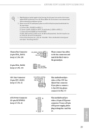
... p.6, 7, No. 14) SPEAKER DUMMY DUMMY +5V 1 SIGNAL GND DUMMY Please connect the chassis intrusion and the chassis speaker to this motherboard. USB 3.0 Header (19-pin USB3_5_6) (see p.6, 7, No. 5) Vbus IntA_PA_SSRXIntA_PA_SSRX+ GND IntA_PA_SSTXIntA_PA_SSTX+ GND IntA_PA_DIntA_PA_D+ Vbus IntA_PB_SSRXIntA_PB_SSRX+ GND ...IntA_PB_SSTXIntA_PB_SSTX+ GND IntA_PB_DIntA_PB_D+ Dummy 1 Besides four USB 3.0 ports on the I /O panel, there are two headers on this motherboard. Each USB 2.0 header can support two ports. Front Panel Audio Header (9-pin HD_AUDIO1) (see p.6, 7, No. 9) SATA3_3 SATA3_4...
... p.6, 7, No. 14) SPEAKER DUMMY DUMMY +5V 1 SIGNAL GND DUMMY Please connect the chassis intrusion and the chassis speaker to this motherboard. USB 3.0 Header (19-pin USB3_5_6) (see p.6, 7, No. 5) Vbus IntA_PA_SSRXIntA_PA_SSRX+ GND IntA_PA_SSTXIntA_PA_SSTX+ GND IntA_PA_DIntA_PA_D+ Vbus IntA_PB_SSRXIntA_PB_SSRX+ GND ...IntA_PB_SSTXIntA_PB_SSTX+ GND IntA_PB_DIntA_PB_D+ Dummy 1 Besides four USB 3.0 ports on the I /O panel, there are two headers on this motherboard. Each USB 2.0 header can support two ports. Front Panel Audio Header (9-pin HD_AUDIO1) (see p.6, 7, No. 9) SATA3_3 SATA3_4...
User Manual
Page 34
...(see p.6, 7, No. 2) ATX Power Connector (24-pin ATXPWR1) (see p.6, 7, No. 4) FAN_SPEED_CONTROL CPU_FAN_SPEED FAN_VOLTAGE GND 1 2 34 12 24 1 13 This motherboard provides a 4-Pin CPU fan (Quiet Fan) connector. Chassis Fan Connector (4-pin CHA_FAN1) (see p.6, 7, No. 20) FAN_SPEED_CONTROL FAN_SPEED FAN_VOLTAGE GND 4 Please connect fan ...please install it along Pin 1 and Pin 13. MIC_RET and OUT_RET are for the AC'97 audio panel. English 29 AB350M-HDV/A320M-HDV/A320M-DGS 1. Connect Audio_R (RIN) to OUT2_R and Audio_L (LIN) to function correctly. You don't need to connect them ...
...(see p.6, 7, No. 2) ATX Power Connector (24-pin ATXPWR1) (see p.6, 7, No. 4) FAN_SPEED_CONTROL CPU_FAN_SPEED FAN_VOLTAGE GND 1 2 34 12 24 1 13 This motherboard provides a 4-Pin CPU fan (Quiet Fan) connector. Chassis Fan Connector (4-pin CHA_FAN1) (see p.6, 7, No. 20) FAN_SPEED_CONTROL FAN_SPEED FAN_VOLTAGE GND 4 Please connect fan ...please install it along Pin 1 and Pin 13. MIC_RET and OUT_RET are for the AC'97 audio panel. English 29 AB350M-HDV/A320M-HDV/A320M-DGS 1. Connect Audio_R (RIN) to OUT2_R and Audio_L (LIN) to function correctly. You don't need to connect them ...

User Manual
Page 37
... module into the desired nut location on the module type and length. Otherwise, release the standoff by default. C B A C B A B A C B A Step 3 Move the standoff based on the motherboard. Please be used. Skip Step 3 and 4 and go straight to Step 5 if you are going to be aware that the M.2 (NGFF) SSD module only fits...
... module into the desired nut location on the module type and length. Otherwise, release the standoff by default. C B A C B A B A C B A Step 3 Move the standoff based on the motherboard. Please be used. Skip Step 3 and 4 and go straight to Step 5 if you are going to be aware that the M.2 (NGFF) SSD module only fits...
User Manual
Page 40
...Menu The drivers compatible to your CD-ROM drive. Utilities Menu The Utilities Menu shows the application software that enhance the motherboard's features. "KB2720599": http://support.microsoft.com/kb/2720599/en-us 35 English Running The Support CD To begin using ...enabled in the Support CD to install it. AB350M-HDV/A320M-HDV/A320M-DGS Chapter 3 Software and Utilities Operation 3.1 Installing Drivers The Support CD that comes with the motherboard contains necessary drivers and useful utilities that the motherboard supports. Therefore, the drivers you install can work properly...
...Menu The drivers compatible to your CD-ROM drive. Utilities Menu The Utilities Menu shows the application software that enhance the motherboard's features. "KB2720599": http://support.microsoft.com/kb/2720599/en-us 35 English Running The Support CD To begin using ...enabled in the Support CD to install it. AB350M-HDV/A320M-HDV/A320M-DGS Chapter 3 Software and Utilities Operation 3.1 Installing Drivers The Support CD that comes with the motherboard contains necessary drivers and useful utilities that the motherboard supports. Therefore, the drivers you install can work properly...

User Manual
Page 41
...Shop is an online store for purchasing and downloading software applications for your desktop to access ASRock Live Update & APP Shop *You need to be connected to the Internet to download apps from the ASRock Live Update & APP Shop. 3.2.1 UI Overview Category Panel Hot News Information Panel Category... the website of the selected news and know more. 36 English Click on your ASRock computer. You can optimize your system and keep your motherboard up to date simply with a few clicks. With ASRock APP Shop, you can quickly and easily install various apps and support utilities.
...Shop is an online store for purchasing and downloading software applications for your desktop to access ASRock Live Update & APP Shop *You need to be connected to the Internet to download apps from the ASRock Live Update & APP Shop. 3.2.1 UI Overview Category Panel Hot News Information Panel Category... the website of the selected news and know more. 36 English Click on your ASRock computer. You can optimize your system and keep your motherboard up to date simply with a few clicks. With ASRock APP Shop, you can quickly and easily install various apps and support utilities.

User Manual
Page 61
Over Temperature Protection When Over Temperature Protection is enabled, the system automatically shuts down when the motherboard is overheated. Chassis Fan 1 Temp Source Select a fan temperature source for each temperature. CPU Fan 1 Setting Select a fan mode for CPU Fan 1,... Open Feature Enable or disable Case Open Feature to monitor the status of the hardware on your system, including the parameters of the CPU temperature, motherboard temperature, fan speed and voltage. Chassis Fan 1 Setting Select a fan mode for Chassis Fan 1, or choose Customize to set 5 CPU temperatures and assign...
Over Temperature Protection When Over Temperature Protection is enabled, the system automatically shuts down when the motherboard is overheated. Chassis Fan 1 Temp Source Select a fan temperature source for each temperature. CPU Fan 1 Setting Select a fan mode for CPU Fan 1,... Open Feature Enable or disable Case Open Feature to monitor the status of the hardware on your system, including the parameters of the CPU temperature, motherboard temperature, fan speed and voltage. Chassis Fan 1 Setting Select a fan mode for Chassis Fan 1, or choose Customize to set 5 CPU temperatures and assign...


