User Manual
Page 2
... for a particular purpose. With respect to the contents of this manual, ASRock does not provide warranty of any kind, either expressed or implied, including but not limited to the following two conditions: (1) this device may not cause harmful interference, and (2) this motherboard contains Perchlorate, a toxic substance controlled in advance. In no responsibility...
... for a particular purpose. With respect to the contents of this manual, ASRock does not provide warranty of any kind, either expressed or implied, including but not limited to the following two conditions: (1) this device may not cause harmful interference, and (2) this motherboard contains Perchlorate, a toxic substance controlled in advance. In no responsibility...
User Manual
Page 3
Introduction 5 1.1 Package Contents 5 1.2 Specifications 6 1.3 Motherboard Layout (960GM-GS3 FX / 960GM-S3 FX 11 1.4 I/O Panel (960GM-GS3 FX 12 1.5 I/O Panel (960GM-S3 FX 13 2 . Installation 14 Pre-installation Precautions 14 2.1 CPU Installation 15 2.2 Installation of CPU Fan and Heatsink 15 2.3 Installation of Memory Modules (DIMM 16 2.4 Expansion Slots (...
Introduction 5 1.1 Package Contents 5 1.2 Specifications 6 1.3 Motherboard Layout (960GM-GS3 FX / 960GM-S3 FX 11 1.4 I/O Panel (960GM-GS3 FX 12 1.5 I/O Panel (960GM-S3 FX 13 2 . Installation 14 Pre-installation Precautions 14 2.1 CPU Installation 15 2.2 Installation of CPU Fan and Heatsink 15 2.3 Installation of Memory Modules (DIMM 16 2.4 Expansion Slots (...
User Manual
Page 5
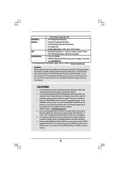
... this manual, chapter 1 and 2 contain introduction of the Support CD. ASRock website http://www.asrock.com If you are using. www.asrock.com/support/index.asp 1.1 Package Contents ASRock 960GM-GS3 FX / 960GM-S3 FX Motherboard (Micro ATX Form Factor: 9.6-in x 7.2-in, 24.4 cm x 18.3 cm) ASRock 960GM-GS3 FX / 960GM-S3 FX Quick Installation Guide ASRock 960GM-GS3 FX / 960GM-S3 FX Support CD 2 x Serial ATA (SATA) Data Cables (Optional) 1 x I/O Panel...
... this manual, chapter 1 and 2 contain introduction of the Support CD. ASRock website http://www.asrock.com If you are using. www.asrock.com/support/index.asp 1.1 Package Contents ASRock 960GM-GS3 FX / 960GM-S3 FX Motherboard (Micro ATX Form Factor: 9.6-in x 7.2-in, 24.4 cm x 18.3 cm) ASRock 960GM-GS3 FX / 960GM-S3 FX Quick Installation Guide ASRock 960GM-GS3 FX / 960GM-S3 FX Support CD 2 x Serial ATA (SATA) Data Cables (Optional) 1 x I/O Panel...
User Manual
Page 8
... sure to read the "SATAII Hard Disk Setup Guide" on page 25 to adjust your SATAII hard disk drive to SATAII connector directly. 8 ASRock website http://www.asrock.com 4. This motherboard supports Dual Channel Memory Technology. CAUTION! 1. Before installing SATAII hard disk to SATAII connector, please read the installation guide of memory modules...
... sure to read the "SATAII Hard Disk Setup Guide" on page 25 to adjust your SATAII hard disk drive to SATAII connector directly. 8 ASRock website http://www.asrock.com 4. This motherboard supports Dual Channel Memory Technology. CAUTION! 1. Before installing SATAII hard disk to SATAII connector, please read the installation guide of memory modules...
User Manual
Page 9
... developed by hardware monitor function and overclock your overclocking record under Windows® environment. Please be shared and worked on the same motherboard. 11. ASRock APP Charger allows you to RAM (S3), hibernation mode (S4) or power off (S5). Please visit our website for the operation...BIOS flash utility embedded in Flash ROM. It helps you can load the OC profile to their own system to access ASRock Instant Flash. ASRock website: http://www.asrock.com/Feature/AppCharger/index.asp 9 7. With this tool and save your OC settings as yours! OC DNA literally tells...
... developed by hardware monitor function and overclock your overclocking record under Windows® environment. Please be shared and worked on the same motherboard. 11. ASRock APP Charger allows you to RAM (S3), hibernation mode (S4) or power off (S5). Please visit our website for the operation...BIOS flash utility embedded in Flash ROM. It helps you can load the OC profile to their own system to access ASRock Instant Flash. ASRock website: http://www.asrock.com/Feature/AppCharger/index.asp 9 7. With this tool and save your OC settings as yours! OC DNA literally tells...
User Manual
Page 10
...resume the system, please check if the CPU fan on the motherboard functions properly and unplug the power cord, then plug it back again. ASRock website: http://www.asrock.com/Feature/SmartView/index.asp 13. Although this motherboard offers stepless control, it can easily recognize which includes below ...than the recommended CPU bus frequencies may depend on -the-go. To meet the standard of the device. 14. ASRock motherboards are required. LAN Application Prioritization: You can configure your real-time newsfeed into an enhanced view for more personal Internet experience...
...resume the system, please check if the CPU fan on the motherboard functions properly and unplug the power cord, then plug it back again. ASRock website: http://www.asrock.com/Feature/SmartView/index.asp 13. Although this motherboard offers stepless control, it can easily recognize which includes below ...than the recommended CPU bus frequencies may depend on -the-go. To meet the standard of the device. 14. ASRock motherboards are required. LAN Application Prioritization: You can configure your real-time newsfeed into an enhanced view for more personal Internet experience...
User Manual
Page 11
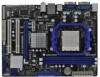
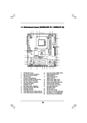
1.3 Motherboard Layout (960GM-GS3 FX / 960GM-S3 FX) PS2 Mouse PS2 Keyboard 12 34 18.3cm (7.2-in) 56 1 PS2_USB_PW1 ATX12V1 CPU_FAN1 7 AT X P W R 1 AM3+ FSB2.6GHz COM1 DDR3 1800 DDR3_A1 (64 bit, 240-FpinSBmo8d0ul0e) ...
1.3 Motherboard Layout (960GM-GS3 FX / 960GM-S3 FX) PS2 Mouse PS2 Keyboard 12 34 18.3cm (7.2-in) 56 1 PS2_USB_PW1 ATX12V1 CPU_FAN1 7 AT X P W R 1 AM3+ FSB2.6GHz COM1 DDR3 1800 DDR3_A1 (64 bit, 240-FpinSBmo8d0ul0e) ...
User Manual
Page 14
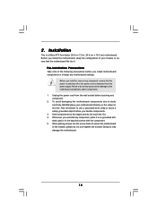
...change any component, place it . Also remember to use a grounded wrist strap or touch a safety grounded object before you uninstall any motherboard settings. When placing screws into it on the carpet or the like. Installation This is detached from the wall socket before you install ...or remove any component. 2. Unplug the power cord from the power supply. Whenever you handle components. 3. Failure to do so may damage the motherboard. 14 Hold components by the edges and do not over-tighten the screws! Doing so may cause severe damage to the chassis, please do ...
...change any component, place it . Also remember to use a grounded wrist strap or touch a safety grounded object before you uninstall any motherboard settings. When placing screws into it on the carpet or the like. Installation This is detached from the wall socket before you install ...or remove any component. 2. Unplug the power cord from the power supply. Whenever you handle components. 3. Failure to do so may damage the motherboard. 14 Hold components by the edges and do not over-tighten the screws! Doing so may cause severe damage to the chassis, please do ...
User Manual
Page 15
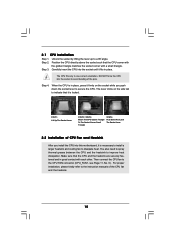
.... Unlock the socket by lifting the lever up to the CPU FAN connector (CPU_FAN1, see Page 11, No. 6). DO NOT force the CPU into this motherboard, it firmly on the side tab to avoid bending of the CPU fan and the heatsink. 15 Make sure that the CPU and the heatsink...
.... Unlock the socket by lifting the lever up to the CPU FAN connector (CPU_FAN1, see Page 11, No. 6). DO NOT force the CPU into this motherboard, it firmly on the side tab to avoid bending of the CPU fan and the heatsink. 15 Make sure that the CPU and the heatsink...
User Manual
Page 16
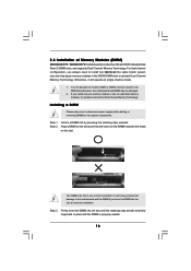
... break on the slot. It is properly seated. 16 Firmly insert the DIMM into DDR3 slot;otherwise, this motherboard and DIMM may be damaged. 2. 2.3 Installation of Memory Modules (DIMM) 960GM-GS3 FX / 960GM-S3 FX motherboard provides two 240-pin DDR3 (Double Data Rate 3) DIMM slots, and supports Dual Channel Memory Technology. Step ...into the slot until the retaining clips at both ends fully snap back in place and the DIMM is not allowed to the motherboard and the DIMM if you install only one correct orientation. notch break notch break The DIMM only fits in the DDR3 DIMM slots...
... break on the slot. It is properly seated. 16 Firmly insert the DIMM into DDR3 slot;otherwise, this motherboard and DIMM may be damaged. 2. 2.3 Installation of Memory Modules (DIMM) 960GM-GS3 FX / 960GM-S3 FX motherboard provides two 240-pin DDR3 (Double Data Rate 3) DIMM slots, and supports Dual Channel Memory Technology. Step ...into the slot until the retaining clips at both ends fully snap back in place and the DIMM is not allowed to the motherboard and the DIMM if you install only one correct orientation. notch break notch break The DIMM only fits in the DDR3 DIMM slots...
User Manual
Page 17
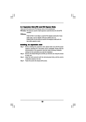
... 1. Keep the screws for the card before you intend to install expansion cards that you start the installation. Step 4. Blue) is completely seated on this motherboard. Step 3. Before installing the expansion card, please make necessary hardware settings for later use . Remove the bracket facing the slot that have the 32-bit...
... 1. Keep the screws for the card before you intend to install expansion cards that you start the installation. Step 4. Blue) is completely seated on this motherboard. Step 3. Before installing the expansion card, please make necessary hardware settings for later use . Remove the bracket facing the slot that have the 32-bit...
User Manual
Page 18
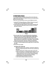
2.5 Multi Monitor Feature This motherboard supports multi monitor feature. If you do not adjust the BIOS setup, the default value of multi monitor feature. Install the onboard VGA driver and ... the benefits of "Share Memory", [Auto], will be your system. Select the display icon identified by the number 2. Click "Extend my Windows desktop onto this motherboard. 4.
2.5 Multi Monitor Feature This motherboard supports multi monitor feature. If you do not adjust the BIOS setup, the default value of multi monitor feature. Install the onboard VGA driver and ... the benefits of "Share Memory", [Auto], will be your system. Select the display icon identified by the number 2. Click "Extend my Windows desktop onto this motherboard. 4.
User Manual
Page 21
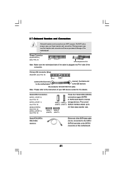
...internal SATAII_3 SATAII_4 storage devices. The current (PORT 2) (PORT 3) SATAII interface allows up to the SATA / SATAII hard disk or the SATAII connector on this motherboard. 21 Serial ATAII Connectors (SATAII_1 (PORT 0): see p.11, No. 17) (SATAII_2 (PORT 1): see p.11, No. 16) (SATAII_3 (PORT 2): see...the red-striped side to the instruction of the connector. SATAII_2 (PORT 1) Serial ATA (SATA) Data Cable (Optional) Either end of the motherboard! • Floppy Connector (33-pin FLOPPY1) (see p.11, No. 14) SATAII_1 (PORT 0) These four Serial ATAII (SATAII) connectors ...
...internal SATAII_3 SATAII_4 storage devices. The current (PORT 2) (PORT 3) SATAII interface allows up to the SATA / SATAII hard disk or the SATAII connector on this motherboard. 21 Serial ATAII Connectors (SATAII_1 (PORT 0): see p.11, No. 17) (SATAII_2 (PORT 1): see p.11, No. 16) (SATAII_3 (PORT 2): see...the red-striped side to the instruction of the connector. SATAII_2 (PORT 1) Serial ATA (SATA) Data Cable (Optional) Either end of the motherboard! • Floppy Connector (33-pin FLOPPY1) (see p.11, No. 14) SATAII_1 (PORT 0) These four Serial ATAII (SATAII) connectors ...
User Manual
Page 22
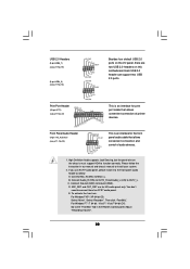
... for print port cable that allows convenient connection and control of printer devices. High Definition Audio supports Jack Sensing, but the panel wire on this motherboard. Connect Ground (GND) to connect them for AC'97 audio panel. You don't need to Ground (GND). Front Panel Audio Header (9-pin HD_AUDIO1) (see p.11...
... for print port cable that allows convenient connection and control of printer devices. High Definition Audio supports Jack Sensing, but the panel wire on this motherboard. Connect Ground (GND) to connect them for AC'97 audio panel. You don't need to Ground (GND). Front Panel Audio Header (9-pin HD_AUDIO1) (see p.11...
User Manual
Page 23
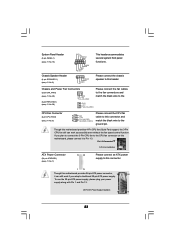
...-pin ATX power supply, please plug your power supply along with Pin 1 and Pin 13. 20-Pin ATX Power Supply Installation 1 13 23 Though this motherboard provides 4-Pin CPU fan (Quiet Fan) support, the 3-Pin CPU fan still can work if you plan to connect the 3-Pin CPU fan to the... CPU fan connector on this motherboard, please connect it can still work successfully even without the fan speed control function. System Panel Header (9-pin PANEL1) (see p.11 No. 15) Chassis Speaker...
...-pin ATX power supply, please plug your power supply along with Pin 1 and Pin 13. 20-Pin ATX Power Supply Installation 1 13 23 Though this motherboard provides 4-Pin CPU fan (Quiet Fan) support, the 3-Pin CPU fan still can work if you plan to connect the 3-Pin CPU fan to the... CPU fan connector on this motherboard, please connect it can still work successfully even without the fan speed control function. System Panel Header (9-pin PANEL1) (see p.11 No. 15) Chassis Speaker...
User Manual
Page 26
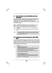
... connector. This section will guide you need to insert and remove the SATA / SATAII HDDs while the system is still power-on this motherboard for SATA host controllers developed thru a joint industry effort. STEP 2: Connect the SATA power cable to the SATA / SATAII hard disk. 2.9 Serial ...ATA (SATA) / Serial ATAII (SATAII) Hard Disks Installation This motherboard adopts AMD SB710 south bridge chipset that it cannot perform Hot Plug if the OS has been installed into the drive bays of the SATA...
... connector. This section will guide you need to insert and remove the SATA / SATAII HDDs while the system is still power-on this motherboard for SATA host controllers developed thru a joint industry effort. STEP 2: Connect the SATA power cable to the SATA / SATAII hard disk. 2.9 Serial ...ATA (SATA) / Serial ATAII (SATAII) Hard Disks Installation This motherboard adopts AMD SB710 south bridge chipset that it cannot perform Hot Plug if the OS has been installed into the drive bays of the SATA...
User Manual
Page 27
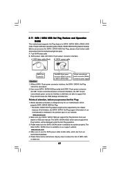
...data cable (Red) B. Please follow below instructions step by the chipset because of its limitation, the SATA / SATAII Hot Plug support information of our motherboard is indicated in RAID / AHCI mode. Before you process the Hot Plug: 1. The latest SATA / SATAII driver is installed into system properly. ... check below operation guide of HDD crash or data loss. 27 Please make sure the SATA / SATAII driver is available on our website: www.asrock.com 2. The SATA / SATAII HDD, which cannot support Hot Plug function, will cause the HDD damage and data loss. 2.11 SATA / ...
...data cable (Red) B. Please follow below instructions step by the chipset because of its limitation, the SATA / SATAII Hot Plug support information of our motherboard is indicated in RAID / AHCI mode. Before you process the Hot Plug: 1. The latest SATA / SATAII driver is installed into system properly. ... check below operation guide of HDD crash or data loss. 27 Please make sure the SATA / SATAII driver is available on our website: www.asrock.com 2. The SATA / SATAII HDD, which cannot support Hot Plug function, will cause the HDD damage and data loss. 2.11 SATA / ...
User Manual
Page 28
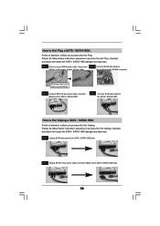
... will cause the SATA / SATAII HDD damage and data loss. Step 2 Unplug SATA 15-pin power cable connector (Black) from SATA / SATAII HDD side. the motherboard's SATAII connector. Step 1 Unplug SATA data cable from SATA / SATAII HDD side. 28 How to Hot Plug a SATA / SATAII HDD: Points of attention, before you...
... will cause the SATA / SATAII HDD damage and data loss. Step 2 Unplug SATA 15-pin power cable connector (Black) from SATA / SATAII HDD side. the motherboard's SATAII connector. Step 1 Unplug SATA data cable from SATA / SATAII HDD side. 28 How to Hot Plug a SATA / SATAII HDD: Points of attention, before you...
User Manual
Page 33
2.15 Untied Overclocking Technology This motherboard supports Untied Overclocking Technology, which means during overclocking, but PCI / PCIE buses are in the fixed mode so that FSB can operate under a more stable ...
2.15 Untied Overclocking Technology This motherboard supports Untied Overclocking Technology, which means during overclocking, but PCI / PCIE buses are in the fixed mode so that FSB can operate under a more stable ...
User Manual
Page 34
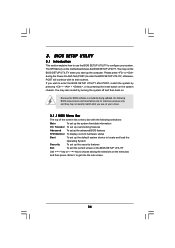
... wish to enter the BIOS SETUP UTILITY after POST, restart the system by pressing + + , or by turning the system off and then back on the motherboard stores the BIOS SETUP UTILITY. If you see on your system. 3.
... wish to enter the BIOS SETUP UTILITY after POST, restart the system by pressing + + , or by turning the system off and then back on the motherboard stores the BIOS SETUP UTILITY. If you see on your system. 3.

