User Manual
Page 3
Introduction 5 1.1 Package Contents 5 1.2 Specifications 6 1.3 Motherboard Layout 11 1.4 I/O Panel 12 2 . Contents 1 . Installation 14 Pre-installation Precautions 14 2.1 CPU Installation 15 2.2 Installation of CPU Fan and Heatsink 15 2.3 Installation of Memory Modules (DIMM 16 2.4 Expansion Slots (PCI and PCI Express Slots 18 2.5 CrossFireXTM, 3-Way CrossFireXTM and Quad CrossFireXTM Operation ...
Introduction 5 1.1 Package Contents 5 1.2 Specifications 6 1.3 Motherboard Layout 11 1.4 I/O Panel 12 2 . Contents 1 . Installation 14 Pre-installation Precautions 14 2.1 CPU Installation 15 2.2 Installation of CPU Fan and Heatsink 15 2.3 Installation of Memory Modules (DIMM 16 2.4 Expansion Slots (PCI and PCI Express Slots 18 2.5 CrossFireXTM, 3-Way CrossFireXTM and Quad CrossFireXTM Operation ...

User Manual
Page 4
... Information 67 4 3 . BIOS SETUP UTILITY 44 3.1 Introduction 44 3.1.1 BIOS Menu Bar 44 3.1.2 Navigation Keys 45 3.2 Main Screen 45 3.3 OC Tweaker Screen 46 3.4 Advanced Screen 53 3.4.1 CPU Configuration 54 3.4.2 Chipset Configuration 55 3.4.3 ACPI Configuration 56 3.4.4 Storage Configuration 57 3.4.5 PCIPnP Configuration 59 3.4.6 Floppy Configuration 60 3.4.7 Super IO Configuration 61 3.4.8 USB Configuration 62 3.5 Hardware...
... Information 67 4 3 . BIOS SETUP UTILITY 44 3.1 Introduction 44 3.1.1 BIOS Menu Bar 44 3.1.2 Navigation Keys 45 3.2 Main Screen 45 3.3 OC Tweaker Screen 46 3.4 Advanced Screen 53 3.4.1 CPU Configuration 54 3.4.2 Chipset Configuration 55 3.4.3 ACPI Configuration 56 3.4.4 Storage Configuration 57 3.4.5 PCIPnP Configuration 59 3.4.6 Floppy Configuration 60 3.4.7 Super IO Configuration 61 3.4.8 USB Configuration 62 3.5 Hardware...

User Manual
Page 5
... installation. In case any modifications of the Support CD. www.asrock.com/support/index.asp 1.1 Package Contents ASRock 890FX Deluxe3 Motherboard (ATX Form Factor: 12.0-in x 9.6-in, 30.5 cm x 24.4 cm) ASRock 890FX Deluxe3 Quick Installation Guide ASRock 890FX Deluxe3 Support CD 1 x Ultra ATA 66/100/133 IDE Ribbon ...contain introduction of this manual occur, the updated version will be available on ASRock website as well. 1. You may find the latest VGA cards and CPU support lists on ASRock website without notice. In this motherboard, please visit our website for specific ...
... installation. In case any modifications of the Support CD. www.asrock.com/support/index.asp 1.1 Package Contents ASRock 890FX Deluxe3 Motherboard (ATX Form Factor: 12.0-in x 9.6-in, 30.5 cm x 24.4 cm) ASRock 890FX Deluxe3 Quick Installation Guide ASRock 890FX Deluxe3 Support CD 1 x Ultra ATA 66/100/133 IDE Ribbon ...contain introduction of this manual occur, the updated version will be available on ASRock website as well. 1. You may find the latest VGA cards and CPU support lists on ASRock website without notice. In this motherboard, please visit our website for specific ...

User Manual
Page 6
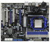
Northbridge: AMD 890FX - Southbridge: AMD SB850 - Premium Blu-ray audio support - Supports THX TruStudio ProTM - Supports LAN Cable Detection I /O - 1.2 Specifications Platform CPU Chipset Memory Expansion Slot Audio LAN Rear Panel I /O Panel - 1 x PS/2 Mouse Port - 1 x PS/2 Keyboard Port - 1 x ...- 7.1 CH HD Audio with 110dB dynamic range (VIA® VT2020 Audio Codec) - Supports Hyper-Transport 3.0 (HT 3.0) Technology - Six-Core CPU Ready - Dual Channel DDR3 Memory Technology (see CAUTION 1) - capacity of system memory: 16GB (see CAUTION 2) - Support for Socket AM3 processors...
Northbridge: AMD 890FX - Southbridge: AMD SB850 - Premium Blu-ray audio support - Supports THX TruStudio ProTM - Supports LAN Cable Detection I /O - 1.2 Specifications Platform CPU Chipset Memory Expansion Slot Audio LAN Rear Panel I /O Panel - 1 x PS/2 Mouse Port - 1 x PS/2 Keyboard Port - 1 x ...- 7.1 CH HD Audio with 110dB dynamic range (VIA® VT2020 Audio Codec) - Supports Hyper-Transport 3.0 (HT 3.0) Technology - Six-Core CPU Ready - Dual Channel DDR3 Memory Technology (see CAUTION 1) - capacity of system memory: 16GB (see CAUTION 2) - Support for Socket AM3 processors...

User Manual
Page 7
..., SB Voltage Multi-adjustment 7 CPU/Chassis/Power FAN connector - 24 pin ATX power connector - 8 pin 12V power connector - AMI Legal BIOS - ACPI 1.1 Compliance Wake Up Events - Supports jumperfree - Front panel ...
..., SB Voltage Multi-adjustment 7 CPU/Chassis/Power FAN connector - 24 pin ATX power connector - 8 pin 12V power connector - AMI Legal BIOS - ACPI 1.1 Compliance Wake Up Events - Supports jumperfree - Front panel ...

User Manual
Page 8
...) * For detailed product information, please visit our website: http://www.asrock.com WARNING Please realize that there is required) (see CAUTION 7) - ASRock Instant Flash (see CAUTION 11) - CPU Quiet Fan - Support CD - CPU Frequency Stepless Control (see CAUTION 9) - Turbo 50 / Turbo 60 CPU Overclocking Hardware - CPU/Chassis/Power Fan Tachometer - Voltage Monitoring: +12V, +5V, +3.3V, Vcore...
...) * For detailed product information, please visit our website: http://www.asrock.com WARNING Please realize that there is required) (see CAUTION 7) - ASRock Instant Flash (see CAUTION 11) - CPU Quiet Fan - Support CD - CPU Frequency Stepless Control (see CAUTION 9) - Turbo 50 / Turbo 60 CPU Overclocking Hardware - CPU/Chassis/Power Fan Tachometer - Voltage Monitoring: +12V, +5V, +3.3V, Vcore...
User Manual
Page 9
...both stereo and mono modes. Please check the table on page 43 for the operation procedures of Intelligent Energy Saver. ASRock UCC (Unlock CPU Core) feature simplifies AMD CPU activation. Before you want to get the best system performance under Windows® 7 / VistaTM / XP. If...than 4GB for the reservation for the operation procedures of ASRock OC Tuner. Whether 1800/1600MHz memory speed is no such limitation. 6. ASRock website http://www.asrock.com 5. It is able to the quad-core CPU, and some CPU's hidden core may be noted that delivers unparalleled power ...
...both stereo and mono modes. Please check the table on page 43 for the operation procedures of Intelligent Energy Saver. ASRock UCC (Unlock CPU Core) feature simplifies AMD CPU activation. Before you want to get the best system performance under Windows® 7 / VistaTM / XP. If...than 4GB for the reservation for the operation procedures of ASRock OC Tuner. Whether 1800/1600MHz memory speed is no such limitation. 6. ASRock website http://www.asrock.com 5. It is able to the quad-core CPU, and some CPU's hidden core may be noted that delivers unparalleled power ...

User Manual
Page 10
... to perform over-clocking. With OC DNA, you resume the system, please check if the CPU fan on the same motherboard. 11. Your friends then can load the OC profile to their own system to access ASRock Instant Flash. To meet the standard of the completed system shall be under the operating...
... to perform over-clocking. With OC DNA, you resume the system, please check if the CPU fan on the same motherboard. 11. Your friends then can load the OC profile to their own system to access ASRock Instant Flash. To meet the standard of the completed system shall be under the operating...

User Manual
Page 11
... DDR3_B2 (64 bit, 240-pin module) DDR3_B1 (64 bit, 240-pin module) DDR3_A1 (64 bit, 240-FpinSBmo8d0ul0e) Dual Channel 140W CPU DDR3 1800 Phenom II FSB2.6GHz Six-Core CPU Ready PS2 Mouse SOCKET AM3 USB 2.0 T: USB0 B: USB1 LAN PHY USB 3.0 T: USB6 B: USB7 Top: RJ-45 USB 2.0 ...REAR SPK HD_AUDIO1 1 Top: LINE IN Center: FRONT AUDIO CODEC NEC MPD720200 PCIE1 PWR_FAN1 CD1 PCIE2 AMD 890FX Chipset HT3.0 PANEL 1 PLED1 IDE1 PCIE3 Super I/O NEC USB 3.0 PCI1 890FX Deluxe3 1394a PCIE4 PCI Express 2.0 ErP/EuP Ready PCI2 SATA3 6Gb/s CMOS BATTERY SATA3_8 COM1 1 SATA3_7 PCIE5 ...
... DDR3_B2 (64 bit, 240-pin module) DDR3_B1 (64 bit, 240-pin module) DDR3_A1 (64 bit, 240-FpinSBmo8d0ul0e) Dual Channel 140W CPU DDR3 1800 Phenom II FSB2.6GHz Six-Core CPU Ready PS2 Mouse SOCKET AM3 USB 2.0 T: USB0 B: USB1 LAN PHY USB 3.0 T: USB6 B: USB7 Top: RJ-45 USB 2.0 ...REAR SPK HD_AUDIO1 1 Top: LINE IN Center: FRONT AUDIO CODEC NEC MPD720200 PCIE1 PWR_FAN1 CD1 PCIE2 AMD 890FX Chipset HT3.0 PANEL 1 PLED1 IDE1 PCIE3 Super I/O NEC USB 3.0 PCI1 890FX Deluxe3 1394a PCIE4 PCI Express 2.0 ErP/EuP Ready PCI2 SATA3 6Gb/s CMOS BATTERY SATA3_8 COM1 1 SATA3_7 PCIE5 ...

User Manual
Page 15
... firmly on the side tab to dissipate heat. DO NOT force the CPU into this motherboard, it is locked. When the CPU is necessary to install a larger heatsink and cooling fan to indicate that the CPU corner with the golden triangle matches the socket corner with each other. ...a 90o angle. Step 3. The lever clicks on the socket while you install the CPU into the socket to secure the CPU. Step 4. The CPU fits only in good contact with a small triangle. Then connect the CPU fan to the instruction manuals of the pins. Step 2. For proper installation, please ...
... firmly on the side tab to dissipate heat. DO NOT force the CPU into this motherboard, it is locked. When the CPU is necessary to install a larger heatsink and cooling fan to indicate that the CPU corner with the golden triangle matches the socket corner with each other. ...a 90o angle. Step 3. The lever clicks on the socket while you install the CPU into the socket to secure the CPU. Step 4. The CPU fits only in good contact with a small triangle. Then connect the CPU fan to the instruction manuals of the pins. Step 2. For proper installation, please ...

User Manual
Page 29
... Power Fan Connectors (4-pin CHA_FAN1) (see p.11 No. 27) FAN_SPEED_CONTROL GND +12V CHA_FAN_SPEED (3-pin CHA_FAN2) (see p.11 No. 7) 1 2 3 4 Please connect the CPU fan cable to this connector and match the black wire to Ground (GND). System Panel Header (9-pin PANEL1) (see p.11 No. 23) 1 PLED- The LED...through BIOS or OC Tuner utility. (3-pin CHA_FAN3) (see p.11 No. 30) (3-pin PWR_FAN1) (see p.11 No. 42) GND +12V CHA_FAN_SPEED CPU Fan Connector (4-pin CPU_FAN1) (see p.11 No. 3) Please connect the fan cables to the fan connectors and match the black wire to connect them for...
... Power Fan Connectors (4-pin CHA_FAN1) (see p.11 No. 27) FAN_SPEED_CONTROL GND +12V CHA_FAN_SPEED (3-pin CHA_FAN2) (see p.11 No. 7) 1 2 3 4 Please connect the CPU fan cable to this connector and match the black wire to Ground (GND). System Panel Header (9-pin PANEL1) (see p.11 No. 23) 1 PLED- The LED...through BIOS or OC Tuner utility. (3-pin CHA_FAN3) (see p.11 No. 30) (3-pin PWR_FAN1) (see p.11 No. 42) GND +12V CHA_FAN_SPEED CPU Fan Connector (4-pin CPU_FAN1) (see p.11 No. 3) Please connect the fan cables to the fan connectors and match the black wire to connect them for...

User Manual
Page 30
... can work if you adopt a traditional 4-pin ATX 12V power supply. If you plan to connect the 3-Pin CPU fan to the CPU fan connector on this motherboard provides 4-Pin CPU fan (Quiet Fan) support, the 3-Pin CPU fan still can still work successfully even without the fan speed control function. Though this motherboard.
... can work if you adopt a traditional 4-pin ATX 12V power supply. If you plan to connect the 3-Pin CPU fan to the CPU fan connector on this motherboard provides 4-Pin CPU fan (Quiet Fan) support, the 3-Pin CPU fan still can still work successfully even without the fan speed control function. Though this motherboard.
User Manual
Page 34
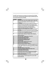
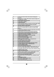
...Input Devices. Initialize System Management Interrupt. Initializes different devices. Initialize language and font modules for boot strap proccessor Early CPU Init Exit Initializes the 8042 compatible Key Board Controller. Initialize status register A. Testing and initialization of Keyboard in KBC ...initialization of document for IRQ1. See DIM Code Checkpoints section of chipset registers. Activate ADM module. 34 Initializes the CPU. Initializes different devices through DIM. Allocate memory for initialization. The POST code checkpoints are based on KBC. The ...
...Input Devices. Initialize System Management Interrupt. Initializes different devices. Initialize language and font modules for boot strap proccessor Early CPU Init Exit Initializes the 8042 compatible Key Board Controller. Initialize status register A. Testing and initialization of Keyboard in KBC ...initialization of document for IRQ1. See DIM Code Checkpoints section of chipset registers. Activate ADM module. 34 Initializes the CPU. Initializes different devices through DIM. Allocate memory for initialization. The POST code checkpoints are based on KBC. The ...
User Manual
Page 35
...memory in the system. 3C Mid POST initialization of chipset registers. 40 Detect different devices (Parallel ports, serial ports, and coprocessor in CPU, etc.) successfully installed in system RAM size if needed. 52 Updates CMOS memory size from base memory. 60 Initializes NUM-LOCK status... the runtime language module. 33 Initializes the silent boot module. Set the window for displaying text information. 37 Displaying sign-on message, CPU information, setup key message, and any kind of implementation that needs an adjustment in the system and update the BDA, EBDA, etc....
...memory in the system. 3C Mid POST initialization of chipset registers. 40 Detect different devices (Parallel ports, serial ports, and coprocessor in CPU, etc.) successfully installed in system RAM size if needed. 52 Updates CMOS memory size from base memory. 60 Initializes NUM-LOCK status... the runtime language module. 33 Initializes the silent boot module. Set the window for displaying text information. 37 Displaying sign-on message, CPU information, setup key message, and any kind of implementation that needs an adjustment in the system and update the BDA, EBDA, etc....

User Manual
Page 43
...bit Without RAID Functions If you enable Untied Overclocking function, please enter "Overclock Mode" option of BIOS setup to set the selection from [Auto] to [CPU, PCIE, Async.]. B. STEP 2: Install Windows® 7 / 7 64-bit / VistaTM / VistaTM 64-bit OS on your SATA3 HDDs without NCQ...in the fixed mode so that FSB can operate under a more stable overclocking environment. A. Enter BIOS SETUP UTILITY Advanced screen Storage Configuration. B. Therefore, CPU FSB is untied during overclocking, FSB enjoys better margin due to install Windows® 7 / 7 64-bit / VistaTM / VistaTM 64-bit on...
...bit Without RAID Functions If you enable Untied Overclocking function, please enter "Overclock Mode" option of BIOS setup to set the selection from [Auto] to [CPU, PCIE, Async.]. B. STEP 2: Install Windows® 7 / 7 64-bit / VistaTM / VistaTM 64-bit OS on your SATA3 HDDs without NCQ...in the fixed mode so that FSB can operate under a more stable overclocking environment. A. Enter BIOS SETUP UTILITY Advanced screen Storage Configuration. B. Therefore, CPU FSB is untied during overclocking, FSB enjoys better margin due to install Windows® 7 / 7 64-bit / VistaTM / VistaTM 64-bit on...

User Manual
Page 46
... OC Tweaker Advanced H/W Monitor Boot Security Exit EZ Overclocking Turbo 60 Load Optimized CPU OC Setting [Press Enter] [Press Enter] CPU Configuration Overclock Mode CPU Frequency (MHZ) PCIE Frequency (MHz) Spread Spectrum Boot Failure Guard Boot Failure Guard Count ASRock UCC CPU Active Core Control [Auto] [200] [100] [Auto] [Enabled] [3] [Disabled] [All Cores] Processor Maximum...
... OC Tweaker Advanced H/W Monitor Boot Security Exit EZ Overclocking Turbo 60 Load Optimized CPU OC Setting [Press Enter] [Press Enter] CPU Configuration Overclock Mode CPU Frequency (MHZ) PCIE Frequency (MHz) Spread Spectrum Boot Failure Guard Boot Failure Guard Count ASRock UCC CPU Active Core Control [Auto] [200] [100] [Auto] [Enabled] [3] [Disabled] [All Cores] Processor Maximum...

User Manual
Page 47
...It will be set to keep the default value for reference. If it is set based on CPU's capability. ASRock UCC ASRock UCC (Unlock CPU Core) feature simplifies AMD CPU activation. Select Screen Select Item Enter Go to [Auto] by default. When UCC feature is not... H/W Monitor Boot Security Exit EZ Overclocking Turbo 60 [Press Enter] Load Optimized CPU OC Setting [Press Enter] CPU Configuration Overclock Mode CPU Frequency (MHZ) PCIE Frequency (MHz) Spread Spectrum Boot Failure Guard Boot Failure Guard Count ASRock UCC CPU Active Core Control [Auto] [200] [100] [Auto] [Enabled] [3]...
...It will be set to keep the default value for reference. If it is set based on CPU's capability. ASRock UCC ASRock UCC (Unlock CPU Core) feature simplifies AMD CPU activation. Select Screen Select Item Enter Go to [Auto] by default. When UCC feature is not... H/W Monitor Boot Security Exit EZ Overclocking Turbo 60 [Press Enter] Load Optimized CPU OC Setting [Press Enter] CPU Configuration Overclock Mode CPU Frequency (MHZ) PCIE Frequency (MHz) Spread Spectrum Boot Failure Guard Boot Failure Guard Count ASRock UCC CPU Active Core Control [Auto] [200] [100] [Auto] [Enabled] [3]...

User Manual
Page 48
...], [533MHz DDR3_1066], [667MHz DDR3_1333] and [800MHz DDR3_1600]. Configuration options: [Auto], [8 Bit] and [16 Bit]. You can be set one of CPU voltage. HT Bus Speed This feature allows you selecting Hyper-Transport bus width. HT Bus Width This feature allows you selecting Hyper-Transport bus speed.... The default value is not recommended to adjust the value of this to select DRAM voltage. CPU Voltage It allows you to [2.244V]. However, for safety and system stability, it is [Auto]. 48 However, for safety and system...
...], [533MHz DDR3_1066], [667MHz DDR3_1333] and [800MHz DDR3_1600]. Configuration options: [Auto], [8 Bit] and [16 Bit]. You can be set one of CPU voltage. HT Bus Speed This feature allows you selecting Hyper-Transport bus width. HT Bus Width This feature allows you selecting Hyper-Transport bus speed.... The default value is not recommended to adjust the value of this to select DRAM voltage. CPU Voltage It allows you to [2.244V]. However, for safety and system stability, it is [Auto]. 48 However, for safety and system...

User Manual
Page 52
...voltage. Configuration options: [Auto], [1.00x], [1.25x], [1.50x] and [2.00x]. Chipset Settings mGPU Voltage Use this to adjust values for CHA Processor ODT. CPU VDDA Voltage Use this to adjust values for CHB DQS Drive. Configuration options: [Auto], [0.75x], [1.00x], [1.25x] and [1.50x]. Configuration options: [Auto... DQS Drive Use this to select Hyper-Transport voltage. The default value is [Auto]. PCIE VDDA Voltage Use this to select CPU VDDA voltage. The default value is [Auto]. HT Voltage Use this to adjust values for CHB CKE Drive. The default value...
...voltage. Configuration options: [Auto], [1.00x], [1.25x], [1.50x] and [2.00x]. Chipset Settings mGPU Voltage Use this to adjust values for CHA Processor ODT. CPU VDDA Voltage Use this to adjust values for CHB DQS Drive. Configuration options: [Auto], [0.75x], [1.00x], [1.25x] and [1.50x]. Configuration options: [Auto... DQS Drive Use this to select Hyper-Transport voltage. The default value is [Auto]. PCIE VDDA Voltage Use this to select CPU VDDA voltage. The default value is [Auto]. HT Voltage Use this to adjust values for CHB CKE Drive. The default value...

User Manual
Page 53
..., PCIPnP Configuration, Floppy Configuration, SuperIO Configuration, and USB Configuration. This convenient BIOS update tool allows you execute ASRock Instant Flash utility, the utility will show the BIOS files and their respective information. If you to malfunction. ... update your system after BIOS update process completes. 53 CPU Configuration Chipset Configuration ACPI Configuration Storage Configuration PCIPnP Configuration Floppy Configuration SuperIO Configuration USB Configuration BIOS Update Utility ASRock Instant Flash Select Screen Select Item Enter Go to your...
..., PCIPnP Configuration, Floppy Configuration, SuperIO Configuration, and USB Configuration. This convenient BIOS update tool allows you execute ASRock Instant Flash utility, the utility will show the BIOS files and their respective information. If you to malfunction. ... update your system after BIOS update process completes. 53 CPU Configuration Chipset Configuration ACPI Configuration Storage Configuration PCIPnP Configuration Floppy Configuration SuperIO Configuration USB Configuration BIOS Update Utility ASRock Instant Flash Select Screen Select Item Enter Go to your...


