User Manual
Page 1
880GM-LE User Manual Version 1.0 Published April 2010 Copyright©2010 ASRock INC. All rights reserved. 1
880GM-LE User Manual Version 1.0 Published April 2010 Copyright©2010 ASRock INC. All rights reserved. 1
User Manual
Page 2
... their respective companies, and are furnished for identification or explanation and to the owners' benefit, without written consent of ASRock Inc. Disclaimer: Specifications and information contained in this manual are used only for informational use only and subject to the...damages (including damages for a particular purpose. "Perchlorate Material-special handling may apply, see www.dtsc.ca.gov/hazardouswaste/perchlorate" ASRock Website: http://www.asrock.com 2 Copyright Notice: No part of this manual may be reproduced, transcribed, transmitted, or translated in any language, in...
... their respective companies, and are furnished for identification or explanation and to the owners' benefit, without written consent of ASRock Inc. Disclaimer: Specifications and information contained in this manual are used only for informational use only and subject to the...damages (including damages for a particular purpose. "Perchlorate Material-special handling may apply, see www.dtsc.ca.gov/hazardouswaste/perchlorate" ASRock Website: http://www.asrock.com 2 Copyright Notice: No part of this manual may be reproduced, transcribed, transmitted, or translated in any language, in...

User Manual
Page 3
Introduction 5 1.1 Package Contents 5 1.2 Specifications 6 1.3 Motherboard Layout 11 1.4 I/O Panel 12 2 . Installation 13 Pre-installation Precautions 13 2.1 CPU Installation 14 2.2 Installation of CPU Fan and Heatsink 14 2.3 Installation of Memory Modules (DIMM 15 2.4 Expansion Slots (PCI and PCI Express Slots 16 2.5 Dual Monitor and Surround Display Features 17 2.6 ATITM Hybrid CrossFireXTM Operation Guide 20 2.7 Jumpers Setup 22 2.8 Onboard Headers and Connectors 23 2.9 SATAII Hard Disk Setup Guide 27 2.10 Serial ATA (SATA) / Serial ATAII (SATAII) Hard Disks Installation ...
Introduction 5 1.1 Package Contents 5 1.2 Specifications 6 1.3 Motherboard Layout 11 1.4 I/O Panel 12 2 . Installation 13 Pre-installation Precautions 13 2.1 CPU Installation 14 2.2 Installation of CPU Fan and Heatsink 14 2.3 Installation of Memory Modules (DIMM 15 2.4 Expansion Slots (PCI and PCI Express Slots 16 2.5 Dual Monitor and Surround Display Features 17 2.6 ATITM Hybrid CrossFireXTM Operation Guide 20 2.7 Jumpers Setup 22 2.8 Onboard Headers and Connectors 23 2.9 SATAII Hard Disk Setup Guide 27 2.10 Serial ATA (SATA) / Serial ATAII (SATAII) Hard Disks Installation ...
User Manual
Page 4
3 . Software Support 60 4.1 Install Operating System 60 4.2 Support CD Information 60 4.2.1 Running Support CD 60 4.2.2 Drivers Menu 60 4.2.3 Utilities Menu 60 4.2.4 Contact Information 60 4 BIOS SETUP UTILITY 37 3.1 Introduction 37 3.1.1 BIOS Menu Bar 37 3.1.2 Navigation Keys 38 3.2 Main Screen 38 3.3 OC Tweaker Screen 39 3.4 Advanced Screen 46 3.4.1 CPU Configuration 47 3.4.2 Chipset Configuration 48 3.4.3 ACPI Configuration 49 3.4.4 Storage Configuration 50 3.4.5 PCIPnP Configuration 52 3.4.6 Floppy Configuration 53 3.4.7 Super IO Configuration 53 3.4.8 USB ...
3 . Software Support 60 4.1 Install Operating System 60 4.2 Support CD Information 60 4.2.1 Running Support CD 60 4.2.2 Drivers Menu 60 4.2.3 Utilities Menu 60 4.2.4 Contact Information 60 4 BIOS SETUP UTILITY 37 3.1 Introduction 37 3.1.1 BIOS Menu Bar 37 3.1.2 Navigation Keys 38 3.2 Main Screen 38 3.3 OC Tweaker Screen 39 3.4 Advanced Screen 46 3.4.1 CPU Configuration 47 3.4.2 Chipset Configuration 48 3.4.3 ACPI Configuration 49 3.4.4 Storage Configuration 50 3.4.5 PCIPnP Configuration 52 3.4.6 Floppy Configuration 53 3.4.7 Super IO Configuration 53 3.4.8 USB ...
User Manual
Page 5
...manual occur, the updated version will be available on ASRock website as well. In this motherboard, please visit our website for purchasing ASRock 880GM-LE motherboard, a reliable motherboard produced under ASRock's consistently stringent quality control. In case any modifications ...step-by-step guide to change without further notice. www.asrock.com/support/index.asp 1.1 Package Contents 1 x ASRock 880GM-LE Motherboard (Micro ATX Form Factor: 9.6-in x 7.8-in, 24.4 cm x 19.8 cm) 1 x ASRock 880GM-LE Quick Installation Guide 1 x ASRock 880GM-LE Support CD 1 x Ultra ATA 66/100/133 IDE ...
...manual occur, the updated version will be available on ASRock website as well. In this motherboard, please visit our website for purchasing ASRock 880GM-LE motherboard, a reliable motherboard produced under ASRock's consistently stringent quality control. In case any modifications ...step-by-step guide to change without further notice. www.asrock.com/support/index.asp 1.1 Package Contents 1 x ASRock 880GM-LE Motherboard (Micro ATX Form Factor: 9.6-in x 7.8-in, 24.4 cm x 19.8 cm) 1 x ASRock 880GM-LE Quick Installation Guide 1 x ASRock 880GM-LE Support CD 1 x Ultra ATA 66/100/133 IDE ...
User Manual
Page 6
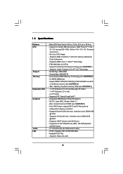
FSB 2600 MHz (5.2 GT/s) - Southbridge: AMD SB710 - Supports ATITM Hybrid CrossFireXTM - Micro ATX Form Factor: 9.6-in x 7.8-in, 24.4 cm x 19.8 cm - Supports AMD OverDriveTM with DVI-D port - Supports Hyper-Transport 3.0 (HT 3.0) Technology - capacity of system memory: 8GB (see CAUTION 3) - resolution up to 2560x1600 @ 75Hz - Supports HDCP function with ACC feature (Advanced Clock Calibration) - Supports AMD's Cool 'n' QuietTM Technology - Support DDR3 1800(OC)/1600(OC)/1333/1066/800 non-ECC, un-buffered memory (see CAUTION 4) - 1 x PCI Express 2.0 x16 slot (blue @ ...
FSB 2600 MHz (5.2 GT/s) - Southbridge: AMD SB710 - Supports ATITM Hybrid CrossFireXTM - Micro ATX Form Factor: 9.6-in x 7.8-in, 24.4 cm x 19.8 cm - Supports AMD OverDriveTM with DVI-D port - Supports Hyper-Transport 3.0 (HT 3.0) Technology - capacity of system memory: 8GB (see CAUTION 3) - resolution up to 2560x1600 @ 75Hz - Supports HDCP function with ACC feature (Advanced Clock Calibration) - Supports AMD's Cool 'n' QuietTM Technology - Support DDR3 1800(OC)/1600(OC)/1333/1066/800 non-ECC, un-buffered memory (see CAUTION 4) - 1 x PCI Express 2.0 x16 slot (blue @ ...
User Manual
Page 7
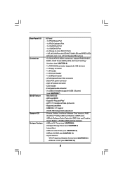
... power connector - 4 pin 12V power connector - VCCM, NB Voltage Multi-adjustment - Intelligent Energy Saver (see CAUTION 13) 7 Supports jumperfree - SMBIOS 2.3.1 Support - ASRock Instant Flash (see CAUTION 8) - Rear Panel I/O Connector BIOS Feature Support CD Unique Feature I/O Panel - 1 x PS/2 Mouse Port - 1 x PS/2 Keyboard ..., AHCI and "Hot Plug" functions (see CAUTION 11) - ACPI 1.1 Compliance Wake Up Events - ASRock OC Tuner (see CAUTION 10) - Explorer, AMD Fusion, ASRock Software Suite (CyberLink DVD Suite and Creative Sound Blaster X-Fi MB) (OEM and Trial Version) - ...
... power connector - 4 pin 12V power connector - VCCM, NB Voltage Multi-adjustment - Intelligent Energy Saver (see CAUTION 13) 7 Supports jumperfree - SMBIOS 2.3.1 Support - ASRock Instant Flash (see CAUTION 8) - Rear Panel I/O Connector BIOS Feature Support CD Unique Feature I/O Panel - 1 x PS/2 Mouse Port - 1 x PS/2 Keyboard ..., AHCI and "Hot Plug" functions (see CAUTION 11) - ACPI 1.1 Compliance Wake Up Events - ASRock OC Tuner (see CAUTION 10) - Explorer, AMD Fusion, ASRock Software Suite (CyberLink DVD Suite and Creative Sound Blaster X-Fi MB) (OEM and Trial Version) - ...
User Manual
Page 8
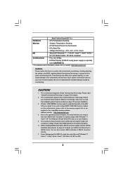
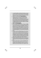
...ErP/EuP ready power supply is required) (see CAUTION 14) * For detailed product information, please visit our website: http://www.asrock.com WARNING Please realize that there is supported depends on page 27 to adjust your system. Before installing SATAII hard disk to ...5V, +3.3V, Vcore OS - Overclocking may be done at your system stability, or even cause damage to SATAII connector directly. 7. CAUTION! 1. ASRock website http://www.asrock.com 4. Please check AMD website for USB 2.0 works fine under Windows® 7 / VistaTM / XP. CPU Quiet Fan - - It ...
...ErP/EuP ready power supply is required) (see CAUTION 14) * For detailed product information, please visit our website: http://www.asrock.com WARNING Please realize that there is supported depends on page 27 to adjust your system. Before installing SATAII hard disk to ...5V, +3.3V, Vcore OS - Overclocking may be done at your system stability, or even cause damage to SATAII connector directly. 7. CAUTION! 1. ASRock website http://www.asrock.com 4. Please check AMD website for USB 2.0 works fine under Windows® 7 / VistaTM / XP. CPU Quiet Fan - - It ...
User Manual
Page 9
... clicks without preparing an additional floppy diskette or other complicated flash utility. Your friends then can update your hardware devices to access ASRock Instant Flash. Frequencies other words, it is able to get the best system performance under the operating system and simplifies the complicated...Cool 'n' Quiet option in the BIOS setup in Flash ROM. With this tool and save your system by ASRock, provides a convenient way for the operation procedures of ASRock OC Tuner. Please be shared and worked on the motherboard functions properly and unplug the power cord, then...
... clicks without preparing an additional floppy diskette or other complicated flash utility. Your friends then can update your hardware devices to access ASRock Instant Flash. Frequencies other words, it is able to get the best system performance under the operating system and simplifies the complicated...Cool 'n' Quiet option in the BIOS setup in Flash ROM. With this tool and save your system by ASRock, provides a convenient way for the operation procedures of ASRock OC Tuner. Please be shared and worked on the motherboard functions properly and unplug the power cord, then...
User Manual
Page 10
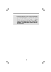
EuP, stands for Energy Using Product, was a provision regulated by European Union to define the power consumption for more details. 10 To meet the standard of the completed system shall be under 100 mA current consumption. According to EuP, the total AC power of 5v standby power efficiency is higher than 50% under 1.00W in off mode condition. For EuP ready power supply selection, we recommend you checking with the power supply manufacturer for the completed system. According to Intel's suggestion, the EuP ready power supply must meet EuP standard, an EuP ready motherboard and ...
EuP, stands for Energy Using Product, was a provision regulated by European Union to define the power consumption for more details. 10 To meet the standard of the completed system shall be under 100 mA current consumption. According to EuP, the total AC power of 5v standby power efficiency is higher than 50% under 1.00W in off mode condition. For EuP ready power supply selection, we recommend you checking with the power supply manufacturer for the completed system. According to Intel's suggestion, the EuP ready power supply must meet EuP standard, an EuP ready motherboard and ...
User Manual
Page 11
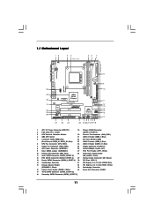
... Top: RJ-45 Top: LINE IN Center: FRONT Bottom: MIC IN LAN AUDIO CODEC Super I/O CD1 1 HD_AUDIO1 LPT1 1 PCIE1 AMD 880G Chipset Hybrid CrossFire PCIE2 880GM-LE IDE1 PWR_FAN1 SATAII_4 SATAII_5 SATAII_6 (PORT 3) (PORT 4) (PORT 5) RoHS PCI1 IR1 1 FLOPPY1 PCI2 USB10_11 1 AMD SB710 Chipset SPEAKER1 1 PLED PWRBTN PANEL 1 1 HDLED RESET 8Mb BIOS...
... Top: RJ-45 Top: LINE IN Center: FRONT Bottom: MIC IN LAN AUDIO CODEC Super I/O CD1 1 HD_AUDIO1 LPT1 1 PCIE1 AMD 880G Chipset Hybrid CrossFire PCIE2 880GM-LE IDE1 PWR_FAN1 SATAII_4 SATAII_5 SATAII_6 (PORT 3) (PORT 4) (PORT 5) RoHS PCI1 IR1 1 FLOPPY1 PCI2 USB10_11 1 AMD SB710 Chipset SPEAKER1 1 PLED PWRBTN PANEL 1 1 HDLED RESET 8Mb BIOS...

User Manual
Page 12
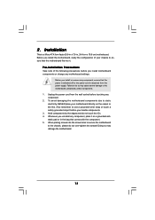
1.4 I/O Panel 1 2 3 4 5 6 7 11 10 9 8 1 PS/2 Mouse Port (Green) 2 VGA/D-Sub Port 3 VGA/DVI-D Port * 4 RJ-45 Port 5 Line In (Light Blue) 6 Front Speaker (Lime) 7 Microphone (Pink) 8 USB 2.0 Ports (USB01) 9 USB 2.0 Ports (USB45) 10 USB 2.0 Ports (USB23) 11 PS/2 Keyboard Port (Purple) * There are allowed to select "Realtek HDA Primary output" to use front panel audio. Please refer to the LAN port. Set "Speaker Configuration" to the table below steps for the LAN port LED indications. Then reboot your system. Click "Device advanced settings", choose "Make front and ...
1.4 I/O Panel 1 2 3 4 5 6 7 11 10 9 8 1 PS/2 Mouse Port (Green) 2 VGA/D-Sub Port 3 VGA/DVI-D Port * 4 RJ-45 Port 5 Line In (Light Blue) 6 Front Speaker (Lime) 7 Microphone (Pink) 8 USB 2.0 Ports (USB01) 9 USB 2.0 Ports (USB45) 10 USB 2.0 Ports (USB23) 11 PS/2 Keyboard Port (Purple) * There are allowed to select "Realtek HDA Primary output" to use front panel audio. Please refer to the LAN port. Set "Speaker Configuration" to the table below steps for the LAN port LED indications. Then reboot your system. Click "Device advanced settings", choose "Make front and ...
User Manual
Page 13
Before you handle components. 3. Also remember to use a grounded wrist strap or touch a safety grounded object before you install the motherboard, study the configuration of the following precautions before touching any component, ensure that comes with the component. 5. 2. Doing so may cause severe damage to ensure that the motherboard fits into the screw holes to secure the motherboard to do not touch the ICs. 4. Hold components by the edges and do so may damage the motherboard. 13 Whenever you uninstall any motherboard settings. Before you install motherboard ...
Before you handle components. 3. Also remember to use a grounded wrist strap or touch a safety grounded object before you install the motherboard, study the configuration of the following precautions before touching any component, ensure that comes with the component. 5. 2. Doing so may cause severe damage to ensure that the motherboard fits into the screw holes to secure the motherboard to do not touch the ICs. 4. Hold components by the edges and do so may damage the motherboard. 13 Whenever you uninstall any motherboard settings. Before you install motherboard ...
User Manual
Page 14
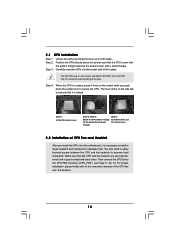
Carefully insert the CPU into this motherboard, it is locked. The lever clicks on the socket while you install the CPU into the socket until it firmly on the side tab to the CPU FAN connector (CPU_FAN1, see Page 11, No. 6). Make sure that the CPU and the heatsink are securely fastened and in good contact with a small triangle. Then connect the CPU fan to indicate that the CPU corner with the golden triangle matches the socket corner with each other. For proper installation, please kindly refer to avoid bending of the pins. 2.1 CPU Installation Step 1. The CPU fits ...
Carefully insert the CPU into this motherboard, it is locked. The lever clicks on the socket while you install the CPU into the socket until it firmly on the side tab to the CPU FAN connector (CPU_FAN1, see Page 11, No. 6). Make sure that the CPU and the heatsink are securely fastened and in good contact with a small triangle. Then connect the CPU fan to indicate that the CPU corner with the golden triangle matches the socket corner with each other. For proper installation, please kindly refer to avoid bending of the pins. 2.1 CPU Installation Step 1. The CPU fits ...
User Manual
Page 15
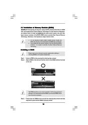
2.3 Installation of Memory Modules (DIMM) 880GM-LE motherboard provides two 240-pin DDR3 (Double Data Rate 3) DIMM slots, and supports Dual Channel Memory Technology. For dual channel configuration, you always need to ...
2.3 Installation of Memory Modules (DIMM) 880GM-LE motherboard provides two 240-pin DDR3 (Double Data Rate 3) DIMM slots, and supports Dual Channel Memory Technology. For dual channel configuration, you always need to ...
User Manual
Page 16
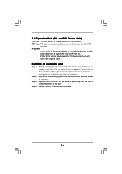
PCI slots: PCI slots are 2 PCI slots and 2 PCI Express slots on the slot. PCIE slots: PCIE1 (PCIE x1 slot; Before installing the expansion card, please make necessary hardware settings for later use . Keep the screws for the card before you intend to install expansion cards that the power supply is switched off or the power cord is used for PCI Express cards with x1 lane width cards, such as Gigabit LAN card, SATA2 card, etc. Step 4. 2.4 Expansion Slots (PCI and PCI Express Slots) There are used to use . White) is unplugged. Step 2. Remove the bracket facing the...
PCI slots: PCI slots are 2 PCI slots and 2 PCI Express slots on the slot. PCIE slots: PCIE1 (PCIE x1 slot; Before installing the expansion card, please make necessary hardware settings for later use . Keep the screws for the card before you intend to install expansion cards that the power supply is switched off or the power cord is used for PCI Express cards with x1 lane width cards, such as Gigabit LAN card, SATA2 card, etc. Step 4. 2.4 Expansion Slots (PCI and PCI Express Slots) There are used to use . White) is unplugged. Step 2. Remove the bracket facing the...

User Manual
Page 17
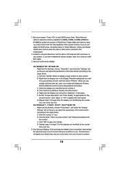
VGA/D-Sub port VGA/DVI-D port 2. Please refer to page 16 for proper expansion card installation procedures for DVI-D and D-Sub to the VGA/D-Sub port on the I /O panel. And connect the D-Sub monitor cable to support dual VGA output so that DVI-D and D-sub can drive same or different display contents. If you have installed onboard VGA driver from our support CD to your system already, you playback HDCP-protected video from our support CD to the VGA/DVI-D port on the I /O panel. When you can easily enjoy the benefits of surround display feature. With the internal dual VGA ...
VGA/D-Sub port VGA/DVI-D port 2. Please refer to page 16 for proper expansion card installation procedures for DVI-D and D-Sub to the VGA/D-Sub port on the I /O panel. And connect the D-Sub monitor cable to support dual VGA output so that DVI-D and D-sub can drive same or different display contents. If you have installed onboard VGA driver from our support CD to your system already, you playback HDCP-protected video from our support CD to the VGA/DVI-D port on the I /O panel. When you can easily enjoy the benefits of surround display feature. With the internal dual VGA ...
User Manual
Page 18
Enter "Share Memory" option to adjust the memory capability to [32MB], [64MB], [128MB] [256MB] or [512MB] to save your change. Install the onboard VGA driver and the add-on VGA card is less than the total capability of the system memory. D. Right-click the display icon and select "Attached", if necessary. For Windows® 7 / 7 64-bit / VistaTM / VistaTM 64-bit OS: Right click the desktop, choose "Personalize", and select the "Display Settings" tab so that you would like to use multiple monitors with your primary monitor, and then select "Primary". Click the number "2" icon. B....
Enter "Share Memory" option to adjust the memory capability to [32MB], [64MB], [128MB] [256MB] or [512MB] to save your change. Install the onboard VGA driver and the add-on VGA card is less than the total capability of the system memory. D. Right-click the display icon and select "Attached", if necessary. For Windows® 7 / 7 64-bit / VistaTM / VistaTM 64-bit OS: Right click the desktop, choose "Personalize", and select the "Display Settings" tab so that you would like to use multiple monitors with your primary monitor, and then select "Primary". Click the number "2" icon. B....
User Manual
Page 19
To use HDCP function with the HDCP scheme such as DVD players, satellite and cable HDTV set -top box - HDCP stands for High-Bandwidth Digital Content Protection, a specification developed by Intel® for more details about HDCP function. Please refer to below instruction for protecting digital entertainment content that uses the DVI interface. What is a copy protection scheme to eliminate the possibility of content as a monitor, television or projector. such as a computer, DVD player or set -top-boxes, as well as few entertainment PCs requires a secure connection to a ...
To use HDCP function with the HDCP scheme such as DVD players, satellite and cable HDTV set -top box - HDCP stands for High-Bandwidth Digital Content Protection, a specification developed by Intel® for more details about HDCP function. Please refer to below instruction for protecting digital entertainment content that uses the DVI interface. What is a copy protection scheme to eliminate the possibility of content as a monitor, television or projector. such as a computer, DVD player or set -top-boxes, as well as few entertainment PCs requires a secure connection to a ...
User Manual
Page 20
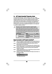
Currently, ATITM Hybrid CrossFireXTM Technology is only supported with Windows® VistaTM / 7 OS, and is not available with Windows® XP OS. Press to [Enabled]. In the future, ATITM Hybrid CrossFireXTM may be supported with Windows® XP OS. What does an ATITM Hybrid CrossFireXTM system include? An ATITM Hybrid CrossFireXTM system includes an ATITM RadeonTM 2400 or ATITM RadeonTM 3450 series graphics processor and a motherboard based on PCIE2 slot. Step 5. Connect the monitor cable to your Windows® taskbar. Then set the option "Surround View" to enter ...
Currently, ATITM Hybrid CrossFireXTM Technology is only supported with Windows® VistaTM / 7 OS, and is not available with Windows® XP OS. Press to [Enabled]. In the future, ATITM Hybrid CrossFireXTM may be supported with Windows® XP OS. What does an ATITM Hybrid CrossFireXTM system include? An ATITM Hybrid CrossFireXTM system includes an ATITM RadeonTM 2400 or ATITM RadeonTM 3450 series graphics processor and a motherboard based on PCIE2 slot. Step 5. Connect the monitor cable to your Windows® taskbar. Then set the option "Surround View" to enter ...
