
User Manual
Page 3
...Introduction 5 1.1 Package Contents 5 1.2 Specifications 6 1.3 Supported AGP VGA Cards Lists 8 1.4 Motherboard Layout 10 1.5 ASRock I/O PlusTM 11 2 Installation 12 Pre-installation Precautions 12 2.1 CPU Installation 13 2.2 Installation of CPU Fan and Heatsink 15 2.3 Installation of Memory Modules (... 3.1 Introduction 24 3.1.1 BIOS Menu Bar 24 3.1.2 Navigation Keys 25 3.2 Main Screen 25 3.3 Advanced Screen 26 3.3.1 CPU Configuration 26 3.3.2 Chipset Configuration 27 3.3.3 ACPI Configuration 29 3.3.4 IDE Configuration 30 3.3.5 PCIPnP Configuration 32 3.3.6 Floppy Configuration...
...Introduction 5 1.1 Package Contents 5 1.2 Specifications 6 1.3 Supported AGP VGA Cards Lists 8 1.4 Motherboard Layout 10 1.5 ASRock I/O PlusTM 11 2 Installation 12 Pre-installation Precautions 12 2.1 CPU Installation 13 2.2 Installation of CPU Fan and Heatsink 15 2.3 Installation of Memory Modules (... 3.1 Introduction 24 3.1.1 BIOS Menu Bar 24 3.1.2 Navigation Keys 25 3.2 Main Screen 25 3.3 Advanced Screen 26 3.3.1 CPU Configuration 26 3.3.2 Chipset Configuration 27 3.3.3 ACPI Configuration 29 3.3.4 IDE Configuration 30 3.3.5 PCIPnP Configuration 32 3.3.6 Floppy Configuration...

User Manual
Page 4
4 Software Support 39 4.1 Install Operating System 39 4.2 Support CD Information 39 4.2.1 Running Support CD 39 4.2.2 Drivers Menu 39• 4.2.3 Utilities Menu 39 4.2.4 ASRock "PC-DIY Live Demo" Program 39 4.2.5 "LGA 775 CPU Installation Live Demo" Program ... 39 4.2.6 Contact Information 39 4
4 Software Support 39 4.1 Install Operating System 39 4.2 Support CD Information 39 4.2.1 Running Support CD 39 4.2.2 Drivers Menu 39• 4.2.3 Utilities Menu 39 4.2.4 ASRock "PC-DIY Live Demo" Program 39 4.2.5 "LGA 775 CPU Installation Live Demo" Program ... 39 4.2.6 Contact Information 39 4

User Manual
Page 5
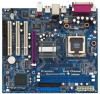
It delivers excellent performance with robust design conforming to ASRock's commitment to BIOS setup and information of the Support CD. ASRock website http://www.asrock.com 1.1 Package Contents ASRock 775i65GV Motherboard (Micro ATX Form Factor: 9.6-in x 8.6-in, 24.4 cm x 21.8 cm) ASRock 775i65GV Quick Installation Guide ASRock 775i65GV Support CD (including LGA 775 CPU Installation Live Demo) One 80-conductor Ultra ATA 66...
It delivers excellent performance with robust design conforming to ASRock's commitment to BIOS setup and information of the Support CD. ASRock website http://www.asrock.com 1.1 Package Contents ASRock 775i65GV Motherboard (Micro ATX Form Factor: 9.6-in x 8.6-in, 24.4 cm x 21.8 cm) ASRock 775i65GV Quick Installation Guide ASRock 775i65GV Support CD (including LGA 775 CPU Installation Live Demo) One 80-conductor Ultra ATA 66...

User Manual
Page 6
...-On-LAN Hardware Monitor:CPU temperature sensing Motherboard temperature sensing CPU overheat shutdown to protect CPU life (ASRock U-COP)(see CAUTION 4) CPU fan tachometer Chassis fan tachometer Voltage monitoring: +12V, +5V, +3.3V, Vcore PCI slots: 3 PCI slots with PCI Specification 2.2 (see CAUTION 5) AMR slot: 1 slot, supports ASRock MR card (Optional) AGI slot: 1 AGI [ASRock Graphics Interface] slot (see...
...-On-LAN Hardware Monitor:CPU temperature sensing Motherboard temperature sensing CPU overheat shutdown to protect CPU life (ASRock U-COP)(see CAUTION 4) CPU fan tachometer Chassis fan tachometer Voltage monitoring: +12V, +5V, +3.3V, Vcore PCI slots: 3 PCI slots with PCI Specification 2.2 (see CAUTION 5) AMR slot: 1 slot, supports ASRock MR card (Optional) AGI slot: 1 AGI [ASRock Graphics Interface] slot (see...

User Manual
Page 7
...ASRock Graphics Interface] slot is not recommended to perform over-clocking. Please refer to the installation guide on page 17. 7. Although this motherboard, it back again. Before you install the PC system. 5. This motherboard supports Dual Channel Memory Technology. Before you resume the system, please check if the CPU...the installed AMR card will run at http://www.microsoft.com/whdc/hwdev/bus/USB/USB2support.mspx 8. CPU FSB Frequency Memory Support Frequency 800 DDR266, DDR320*, DDR400 533 DDR266, DDR333 * When you will automatically shutdown. It may...
...ASRock Graphics Interface] slot is not recommended to perform over-clocking. Please refer to the installation guide on page 17. 7. Although this motherboard, it back again. Before you install the PC system. 5. This motherboard supports Dual Channel Memory Technology. Before you resume the system, please check if the CPU...the installed AMR card will run at http://www.microsoft.com/whdc/hwdev/bus/USB/USB2support.mspx 8. CPU FSB Frequency Memory Support Frequency 800 DDR266, DDR320*, DDR400 533 DDR266, DDR333 * When you will automatically shutdown. It may...

User Manual
Page 14
...is within the socket and properly mated to the orient keys. Step 4. Carefully place the CPU into the socket by using a purely vertical motion. Rotate the load plate onto the IHS.... Step 4-3. Remove PnP Cap (Pick and Place Cap): Use your left hand index finger and thumb to support the load plate edge, engage PnP cap with right hand thumb and peel the cap from the socket while... pressing on load plate, engage the load lever. Close the socket: Step 4-1. Verify that the CPU is recommended to use the cap tab to handle and avoid kicking off the PnP cap. Step 2-3. For ...
...is within the socket and properly mated to the orient keys. Step 4. Carefully place the CPU into the socket by using a purely vertical motion. Rotate the load plate onto the IHS.... Step 4-3. Remove PnP Cap (Pick and Place Cap): Use your left hand index finger and thumb to support the load plate edge, engage PnP cap with right hand thumb and peel the cap from the socket while... pressing on load plate, engage the load lever. Close the socket: Step 4-1. Verify that the CPU is recommended to use the cap tab to handle and avoid kicking off the PnP cap. Step 2-3. For ...

User Manual
Page 15
...kindly refer to dissipate heat. Step 2. If you need to spray thermal interface material between the CPU and the heatsink to improve heat dissipation. Step 6. Below is equipped with the CPU fan connector on the socket surface. Step 3. Ensure fan cables are securely fastened and in good... throughholes. Secure excess cable with tie-wrap to ensure cable does not interfere with each other components. 15 Ensure that supports Intel 775-Pin CPU. Before you installed the heatsink, you press down on the motherboard. Align fasteners with remaining fasteners. Then connect the...
...kindly refer to dissipate heat. Step 2. If you need to spray thermal interface material between the CPU and the heatsink to improve heat dissipation. Step 6. Below is equipped with the CPU fan connector on the socket surface. Step 3. Ensure fan cables are securely fastened and in good... throughholes. Secure excess cable with tie-wrap to ensure cable does not interfere with each other components. 15 Ensure that supports Intel 775-Pin CPU. Before you installed the heatsink, you press down on the motherboard. Align fasteners with remaining fasteners. Then connect the...

User Manual
Page 22
... (see p.10 No. 26) ATX 12V Connector (4-pin ATX12V1) (see p.10 No. 6) Please connect an ATX power supply to support a COM port module. Note: If you use a 3-pin CPU fan cable, insert it to the connector by aligning it with ATX 12V plug to this connector. ATX Power Connector (20... it can provides sufficient power. GND +12V CHA_FAN_SPEED Please connect a chassis fan cable to this connector, then match the black wire to the ground pin. CPU Fan Connector (4-pin CPU_FAN1) (see p.10 No. 14) PLED+ PLEDPWRBTN# GND 1 DUMMY RESET# GND HDLEDHDLED+ 1 SPEAKER DUMMY DUMMY +5V This header ...
... (see p.10 No. 26) ATX 12V Connector (4-pin ATX12V1) (see p.10 No. 6) Please connect an ATX power supply to support a COM port module. Note: If you use a 3-pin CPU fan cable, insert it to the connector by aligning it with ATX 12V plug to this connector. ATX Power Connector (20... it can provides sufficient power. GND +12V CHA_FAN_SPEED Please connect a chassis fan cable to this connector, then match the black wire to the ground pin. CPU Fan Connector (4-pin CPU_FAN1) (see p.10 No. 14) PLED+ PLEDPWRBTN# GND 1 DUMMY RESET# GND HDLEDHDLED+ 1 SPEAKER DUMMY DUMMY +5V This header ...

User Manual
Page 27
... system with an Intel Pentium®4 processor that supports Hyper-Threading technology and an operating system that includes optimization for this motherboard. CPU Thermal Throttling You may select [Enabled] to enable P4 CPU internal thermal control mechanism to [Auto] if using... Burst Length [4 Clocks] [8 Clocks] [4] Init. If it shows "Unlocked", you will be hidden if the installed CPU does not support Hyper-Threading technology. 3.3.2 Chipset Configuration BIOS SETUP UTILITY Advanced Chipset Configuration DRAM Frequency [Auto] Flexibility Option [Disabled] Configure ...
... system with an Intel Pentium®4 processor that supports Hyper-Threading technology and an operating system that includes optimization for this motherboard. CPU Thermal Throttling You may select [Enabled] to enable P4 CPU internal thermal control mechanism to [Auto] if using... Burst Length [4 Clocks] [8 Clocks] [4] Init. If it shows "Unlocked", you will be hidden if the installed CPU does not support Hyper-Threading technology. 3.3.2 Chipset Configuration BIOS SETUP UTILITY Advanced Chipset Configuration DRAM Frequency [Auto] Flexibility Option [Disabled] Configure ...

User Manual
Page 35
USB 2.0 Support Use this item to enable or disable the use of the CPU temperature, motherboard temperature, CPU fan speed, chassis fan speed, and the critical voltage. BIOS SETUP UTILITY Main Advanced H/W Monitor Boot Security Exit Hardware Health Event Monitoring CPU Temperature M / B Temperature CPU Fan Speed ..., keyboard,... 3.3.8 USB Configuration Advanced BIOS SETUP UTILITY USB Configuration USB Devices Enabled : None USB Controller USB 2.0 Support Legacy USB Support [Enabled] [Enabled] [Disabled] To enable or disable the onboard USB controllers. +F1 F9 F10 ESC Select ...
USB 2.0 Support Use this item to enable or disable the use of the CPU temperature, motherboard temperature, CPU fan speed, chassis fan speed, and the critical voltage. BIOS SETUP UTILITY Main Advanced H/W Monitor Boot Security Exit Hardware Health Event Monitoring CPU Temperature M / B Temperature CPU Fan Speed ..., keyboard,... 3.3.8 USB Configuration Advanced BIOS SETUP UTILITY USB Configuration USB Devices Enabled : None USB Controller USB 2.0 Support Legacy USB Support [Enabled] [Enabled] [Disabled] To enable or disable the onboard USB controllers. +F1 F9 F10 ESC Select ...
User Manual
Page 39
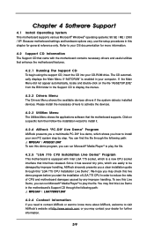
... this live demo, which is enabled in the motherboard's Support CD through the following path: ..\ MPEGAV \ AVSEQ01.DAT To see this Live Demo in your own PC system step by improper handling, ASRock sincerely presents you start the installation of CPU and motherboard damages caused by any improper handling. Because motherboard settings and...
... this live demo, which is enabled in the motherboard's Support CD through the following path: ..\ MPEGAV \ AVSEQ01.DAT To see this Live Demo in your own PC system step by improper handling, ASRock sincerely presents you start the installation of CPU and motherboard damages caused by any improper handling. Because motherboard settings and...

Quick Installation Guide
Page 4
... well. It delivers excellent performance with robust design conforming to ASRock's commitment to change without further notice. ASRock website http://www.asrock.com 1.1 Package Contents ASRock 775i65GV Motherboard (Micro ATX Form Factor: 9.6-in x 8.6-in, 24.4 cm x 21.8 cm) ASRock 775i65GV Quick Installation Guide ASRock 775i65GV Support CD (including LGA 775 CPU Installation Live Demo) One 80-conductor Ultra ATA 66/100...
... well. It delivers excellent performance with robust design conforming to ASRock's commitment to change without further notice. ASRock website http://www.asrock.com 1.1 Package Contents ASRock 775i65GV Motherboard (Micro ATX Form Factor: 9.6-in x 8.6-in, 24.4 cm x 21.8 cm) ASRock 775i65GV Quick Installation Guide ASRock 775i65GV Support CD (including LGA 775 CPU Installation Live Demo) One 80-conductor Ultra ATA 66/100...

Quick Installation Guide
Page 5
... (see CAUTION 6) English USB 2.0: 8 USB 2.0 ports: includes 6 default USB 2.0 ports on the rear panel, plus one header to support 2 additional USB 2.0 ports (see CAUTION 7) ASRock I/O PlusTM: 1 PS/2 mouse port, 1 PS/2 keyboard port, 1 VGA port, 1 parallel port: ECP/EPP support, 6 default USB 2.0 ports, 1 RJ-45 port, Audio Jack: Line In / Line Out / Microphone 5 ASRock 775i65GV Motherboard
... (see CAUTION 6) English USB 2.0: 8 USB 2.0 ports: includes 6 default USB 2.0 ports on the rear panel, plus one header to support 2 additional USB 2.0 ports (see CAUTION 7) ASRock I/O PlusTM: 1 PS/2 mouse port, 1 PS/2 keyboard port, 1 VGA port, 1 parallel port: ECP/EPP support, 6 default USB 2.0 ports, 1 RJ-45 port, Audio Jack: Line In / Line Out / Microphone 5 ASRock 775i65GV Motherboard

Quick Installation Guide
Page 6
... SP4. To improve heat dissipation, remember to the "Supported AGP VGA Cards List" on the motherboard functions properly and unplug the power cord, then plug it will not be able to perform over-clocking. For the information of the system or damage the CPU. 6 ASRock 775i65GV Motherboard English Please check the table below for...
... SP4. To improve heat dissipation, remember to the "Supported AGP VGA Cards List" on the motherboard functions properly and unplug the power cord, then plug it will not be able to perform over-clocking. For the information of the system or damage the CPU. 6 ASRock 775i65GV Motherboard English Please check the table below for...

Quick Installation Guide
Page 10
... open position at approximately 135 degrees. Verify that the CPU is within the socket and properly mated to support the load plate edge, engage PnP cap with black lines. Step 3. Open the socket: Step 1-1. Rotate the load plate to assist in removal. 10 ASRock 775i65GV Motherboard Pin1 orientation key notch orientation key notch Pin1...
... open position at approximately 135 degrees. Verify that the CPU is within the socket and properly mated to support the load plate edge, engage PnP cap with black lines. Step 3. Open the socket: Step 1-1. Rotate the load plate to assist in removal. 10 ASRock 775i65GV Motherboard Pin1 orientation key notch orientation key notch Pin1...

Quick Installation Guide
Page 18
English ATX 12V Connector (4-pin ATX12V1) (see p.2 No. 30) Please note that it is used to support a COM port module. Note: If you use a 3-pin CPU fan cable, insert it to the connector by aligning it with ATX 12V plug to this connector so that it can provides sufficient power. ATX ... (3-pin CHA_FAN1) (see p.2 No. 13) Please connect the chassis speaker to this (see p.2 No. 23) This COM port header is necessary to the ground pin. CPU Fan Connector You may connect either a 3-pin (4-pin CPU_FAN1) or a 4-pin CPU fan cable to power up. 18 ASRock 775i65GV Motherboard
English ATX 12V Connector (4-pin ATX12V1) (see p.2 No. 30) Please note that it is used to support a COM port module. Note: If you use a 3-pin CPU fan cable, insert it to the connector by aligning it with ATX 12V plug to this connector so that it can provides sufficient power. ATX ... (3-pin CHA_FAN1) (see p.2 No. 13) Please connect the chassis speaker to this (see p.2 No. 23) This COM port header is necessary to the ground pin. CPU Fan Connector You may connect either a 3-pin (4-pin CPU_FAN1) or a 4-pin CPU fan cable to power up. 18 ASRock 775i65GV Motherboard

Quick Installation Guide
Page 20
... a clear installation guide through the following path: ..\ MPEGAV \ AVSEQ01.DAT "LGA 775 CPU Installation Live Demo" This motherboard is enabled in order to be found through the following path: ..\ MPEGAV \ LGA775INST.DAT 20 ASRock 775i65GV Motherboard English Software Support CD information This motherboard supports various Microsoft® Windows® operating systems: 98 SE/ ME / 2000...
... a clear installation guide through the following path: ..\ MPEGAV \ AVSEQ01.DAT "LGA 775 CPU Installation Live Demo" This motherboard is enabled in order to be found through the following path: ..\ MPEGAV \ LGA775INST.DAT 20 ASRock 775i65GV Motherboard English Software Support CD information This motherboard supports various Microsoft® Windows® operating systems: 98 SE/ ME / 2000...


